2007 ISUZU KB P190 battery
[x] Cancel search: batteryPage 3627 of 6020
Starting System – V6 Page 6D1-2–19
4 Major Service Operations
Disconnection of the battery affects certain
vehicle electronic systems. Refer to 00
Warnings, Cautions and Notes before
disconnecting the battery.
4.1 Starter Motor
Remove
The starter motor is in close proximity to the
left-hand side exhaust manifold and engine
pipe. Allow the engine to cool before
attempting to remove the starter motor.
1 Refer to 1.1 W ARNING, CAUTION and NOTES in this Service Information before disconnecting the battery.
2 Disconnect the battery ground lead.
3 Raise the front of the vehicle. For jacking locations, refer to 0A General Information.
4 Put safety stands in place.
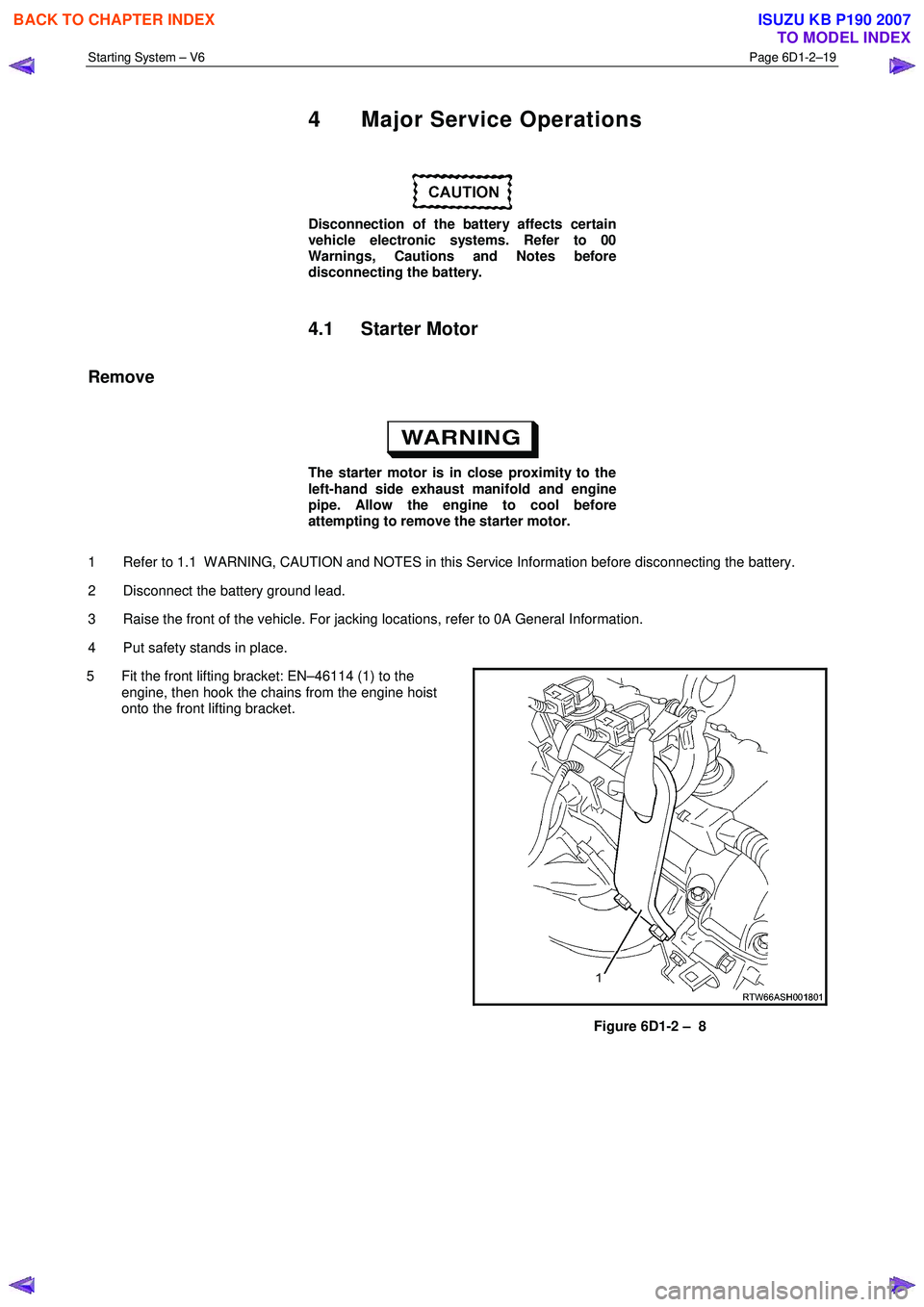
5 Fit the front lifting bracket: EN–46114 (1) to the engine, then hook the chains from the engine hoist
onto the front lifting bracket.
Figure 6D1-2 – 8
BACK TO CHAPTER INDEX
TO MODEL INDEX
ISUZU KB P190 2007
Page 3629 of 6020
Starting System – V6 Page 6D1-2–21
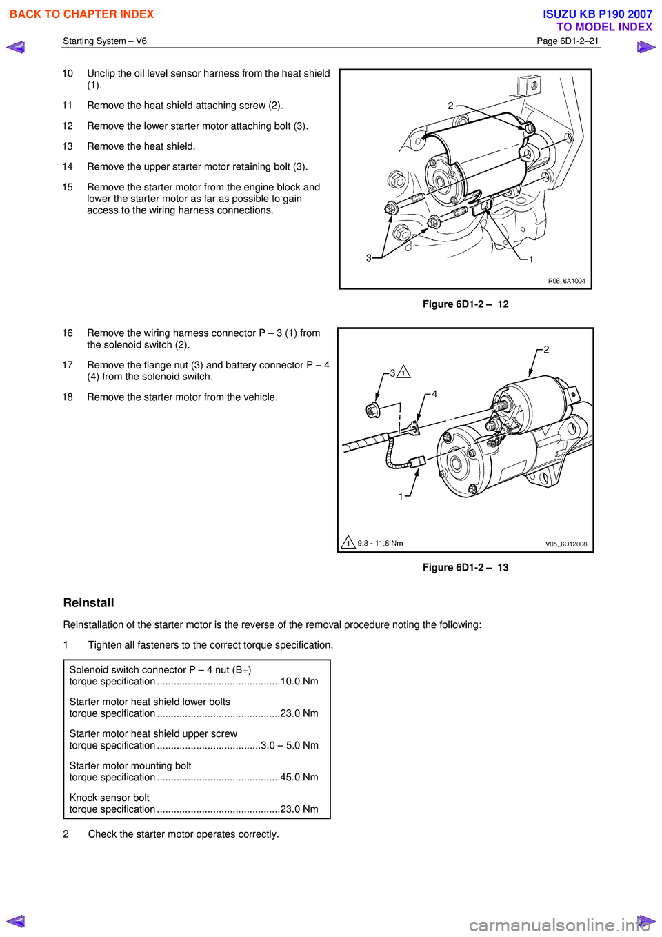
10 Unclip the oil level sensor harness from the heat shield
(1).
11 Remove the heat shield attaching screw (2).
12 Remove the lower starter motor attaching bolt (3).
13 Remove the heat shield.
14 Remove the upper starter motor retaining bolt (3).
15 Remove the starter motor from the engine block and lower the starter motor as far as possible to gain
access to the wiring harness connections.
Figure 6D1-2 – 12
16 Remove the wiring harness connector P – 3 (1) from the solenoid switch (2).
17 Remove the flange nut (3) and battery connector P – 4 (4) from the solenoid switch.
18 Remove the starter motor from the vehicle.
Figure 6D1-2 – 13
Reinstall
Reinstallation of the starter motor is the reverse of the removal procedure noting the following:
1 Tighten all fasteners to the correct torque specification.
Solenoid switch connector P – 4 nut (B+)
torque specification ............................................10.0 Nm
Starter motor heat shield lower bolts
torque specification ............................................23.0 Nm
Starter motor heat shield upper screw
torque specification .....................................3.0 – 5.0 Nm
Starter motor mounting bolt
torque specification ............................................45.0 Nm
Knock sensor bolt
torque specification ............................................23.0 Nm
2 Check the starter motor operates correctly.
BACK TO CHAPTER INDEX
TO MODEL INDEX
ISUZU KB P190 2007
Page 3630 of 6020
Starting System – V6 Page 6D1-2–22
4.3 Starter Motor Bench Tests
Preliminary Checks
1 Check the drive assembly is fully retracted.
2 Check the drive assembly pinion turns freely on the planetary drive shaft.
3 Perform the No Load Test (as outlined in this Section) if the drive assembly is not fully retracted.
4 Disassemble and service the starter motor if it fails the No Load test, refer to 4.4 Starter Motor Disassemble and
Reassemble in this Section.
Pull-in Test
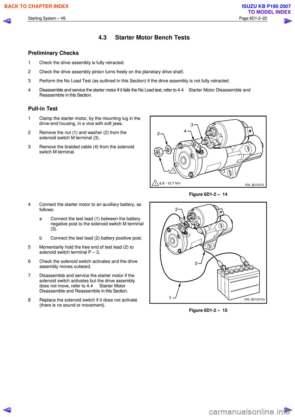
1 Clamp the starter motor, by the mounting lug in the drive-end housing, in a vice with soft jaws.
2 Remove the nut (1) and washer (2) from the solenoid switch M terminal (3).
3 Remove the braided cable (4) from the solenoid switch M terminal.
Figure 6D1-2 – 14
4 Connect the starter motor to an auxiliary battery, as follows:
a Connect the test lead (1) between the battery negative post to the solenoid switch M terminal
(3).
b Connect the test lead (2) battery positive post.
5 Momentarily hold the free end of test lead (2) to solenoid switch terminal P – 3.
6 Check the solenoid switch activates and the drive assembly moves outward.
7 Disassemble and service the starter motor if the solenoid switch activates but the drive assembly
does not move, refer to 4.4 Starter Motor
Disassemble and Reassemble in this Section.
8 Replace the solenoid switch if it does not activate (there is no sound or movement).
Figure 6D1-2 – 15
BACK TO CHAPTER INDEX
TO MODEL INDEX
ISUZU KB P190 2007
Page 3631 of 6020
Starting System – V6 Page 6D1-2–23
Hold-in Test
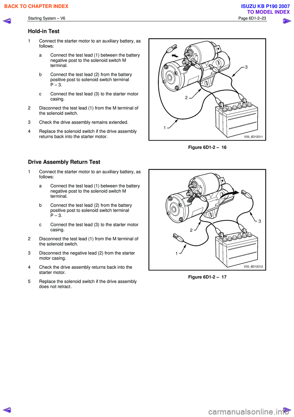
1 Connect the starter motor to an auxiliary battery, as
follows:
a Connect the test lead (1) between the battery negative post to the solenoid switch M
terminal.
b Connect the test lead (2) from the battery positive post to solenoid switch terminal
P – 3.
c Connect the test lead (3) to the starter motor casing.
2 Disconnect the test lead (1) from the M terminal of the solenoid switch.
3 Check the drive assembly remains extended.
4 Replace the solenoid switch if the drive assembly returns back into the starter motor.
Figure 6D1-2 – 16
Drive Assembly Return Test
1 Connect the starter motor to an auxiliary battery, as follows:
a Connect the test lead (1) between the battery negative post to the solenoid switch M
terminal.
b Connect the test lead (2) from the battery positive post to solenoid switch terminal
P – 3.
c Connect the test lead (3) to the starter motor casing.
2 Disconnect the test lead (1) from the M terminal of the solenoid switch.
3 Disconnect the negative lead (2) from the starter motor casing.
4 Check the drive assembly returns back into the starter motor.
5 Replace the solenoid switch if the drive assembly does not retract.
Figure 6D1-2 – 17
BACK TO CHAPTER INDEX
TO MODEL INDEX
ISUZU KB P190 2007
Page 3632 of 6020
Starting System – V6 Page 6D1-2–24
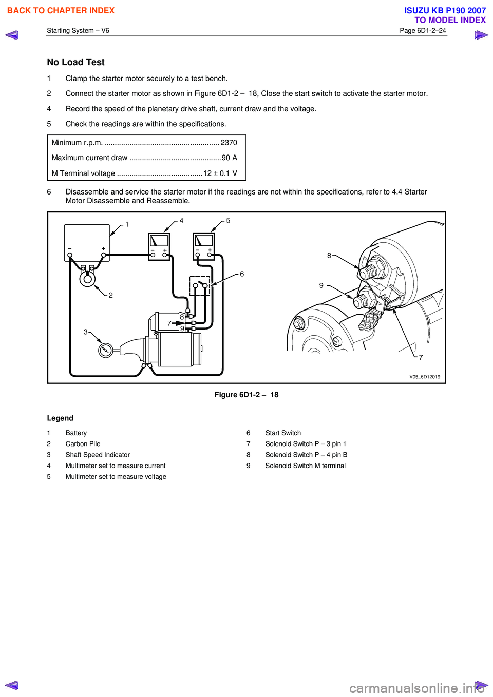
No Load Test
1 Clamp the starter motor securely to a test bench.
2 Connect the starter motor as shown in Figure 6D1-2 – 18, Close the start switch to activate the starter motor.
4 Record the speed of the planetary drive shaft, current draw and the voltage.
5 Check the readings are within the specifications.
Minimum r.p.m. ....................................................... 2370
Maximum current draw ............................................ 90 A
M Terminal voltage ......................................... 12 ± 0.1 V
6 Disassemble and service the starter motor if the readings are not within the specifications, refer to 4.4 Starter
Motor Disassemble and Reassemble.
Figure 6D1-2 – 18
Legend
1 Battery
2 Carbon Pile
3 Shaft Speed Indicator
4 Multimeter set to measure current
5 Multimeter set to measure voltage 6 Start Switch
7 Solenoid Switch P – 3 pin 1
8 Solenoid Switch P – 4 pin B
9 Solenoid Switch M terminal
BACK TO CHAPTER INDEX
TO MODEL INDEX
ISUZU KB P190 2007
Page 3636 of 6020

Starting System – V6 Page 6D1-2–28
10 Fit a rubber band (1) around the plunger and
switch housing to avoid ejecting the plunger.
11 Hold the solenoid switch vertically with the plunger pointing upwards.
12 Use a power supply (2) capable of supplying 30 A or use a battery and a variable resistor.
13 Set the power supply to 3.0 V.
14 Connect the power supply negative lead to the solenoid switch body.
15 Connect the power supply positive lead to the solenoid switch terminal P – 3 (5).
16 Connect a test lamp (3) between the solenoid switch terminal P – 4 (7) and the battery.
17 Connect a multimeter set to measure voltage (4) between the solenoid switch terminal P – 3 (5)
and the solenoid switch housing.
18 Press the solenoid plunger in until the test lamp illuminates.
19 Allow the plunger to move out by 8 – 10 mm.
20 Hold the plunger in this position.
The test duration for the following step
should be no more than 2 seconds.
Figure 6D1-2 – 25
21 Slowly increase the power supply voltage on the solenoid switch terminal P – 3 until the plunger pulls in.
22 Record the multimeter reading and reduce the voltage applied to the solenoid switch terminal P – 3.
23 Replace the solenoid switch if the voltage reading is significantly higher than the specification.
Pull-in voltage @ 20 °C ............................................ 8.0 V
24 Check the continuity across the main contacts in the switch.
25 Increase the voltage on the solenoid switch terminal P – 3 (5) until the plunger pulls in.
26 Ensure the test lamp illuminates fully.
BACK TO CHAPTER INDEX
TO MODEL INDEX
ISUZU KB P190 2007
Page 3641 of 6020
Battery Page 6D1-3–1
6D1-3
Battery – V6
ATTENTION
Before performing any service operation or other procedure described in this Section, refer to 1.1
WARNING, CAUTION and NOTES for correct workshop practices with regard to safety and/or property
damage.
1 General Information ............................................................................................................ ...................3
1.1 WARNING, CAUTION and NOTES ..................................................................................................... ................... 3
Definition of WARNING, CAUTION and NOTE Statements ............................................................................. .... 3
1.2 Battery Terminals and Cables............................................................................................................................... 4
1.3 Battery Ratings ...................................................................................................................................................... 4
Reserve Capacity ............................................................................................................... .................................... 4
Cold Cranking Amps ............................................................................................................................................. 5
Ratings.................................................................................................................................................................... 5
2 Safety Precautions .................................................................................................................................6
3 Diagnosis ................................................................................................................................................7
3.1 Diagnostic Procedures .......................................................................................................................................... 7
Introduction ............................................................................................................................................................ 7
Test Description ..................................................................................................................................................... 7
Diagnostic Table Notes ......................................................................................................................................... 7
Diagnostic Table .................................................................................................................................................... 7
3.2 Battery Inspection.................................................................................................................................................. 8
3.3 Hydrometer Test .................................................................................................................................................... 9
3.4 Load Test ...................................................................................................................... ........................................ 10
High Rate Discharge Load Test .................................................................................................. ........................ 10
Alternate Load Test ............................................................................................................................................. 11
3.5 Battery Current Draw Test...................................................................................................... ............................. 11
Test Preparation................................................................................................................................................... 11
Test Procedure ..................................................................................................................................................... 12
Fault Diagnosis .................................................................................................................................................... 12
Restore.................................................................................................................................................................. 13
4 Service Operations ...............................................................................................................................14
4.1 Battery................................................................................................................................................................... 14
Remove ......................................................................................................................... ........................................ 14
Reinstall ................................................................................................................................................................ 14
4.2 Battery Charge ................................................................................................................. .................................... 15
Safety Precautions............................................................................................................. .................................. 15
Battery Charge Procedure....................................................................................................... ............................ 15
4.3 Emergency Jump Starting Procedure .............................................................................................. .................. 16
Safety Precautions............................................................................................................................................... 16
Jump Starting Procedure ........................................................................................................ ............................ 16
4.4 Dry Charged Batteries ......................................................................................................................................... 18
Storage.................................................................................................................................................................. 18
Activation..................................................................................................................... ......................................... 18
Post Activation Tests .......................................................................................................... ................................ 18
5 Specifications .......................................................................................................................................19
BACK TO CHAPTER INDEX
TO MODEL INDEX
ISUZU KB P190 2007
Page 3642 of 6020

Battery Page 6D1-3–2
6 Torque Wrench Specifications............................................................................................................20
7 Special Tools ........................................................................................................................................21
BACK TO CHAPTER INDEX
TO MODEL INDEX
ISUZU KB P190 2007