2007 ISUZU KB P190 display
[x] Cancel search: displayPage 5588 of 6020
Cruise Control – HFV6 Page 8C–10
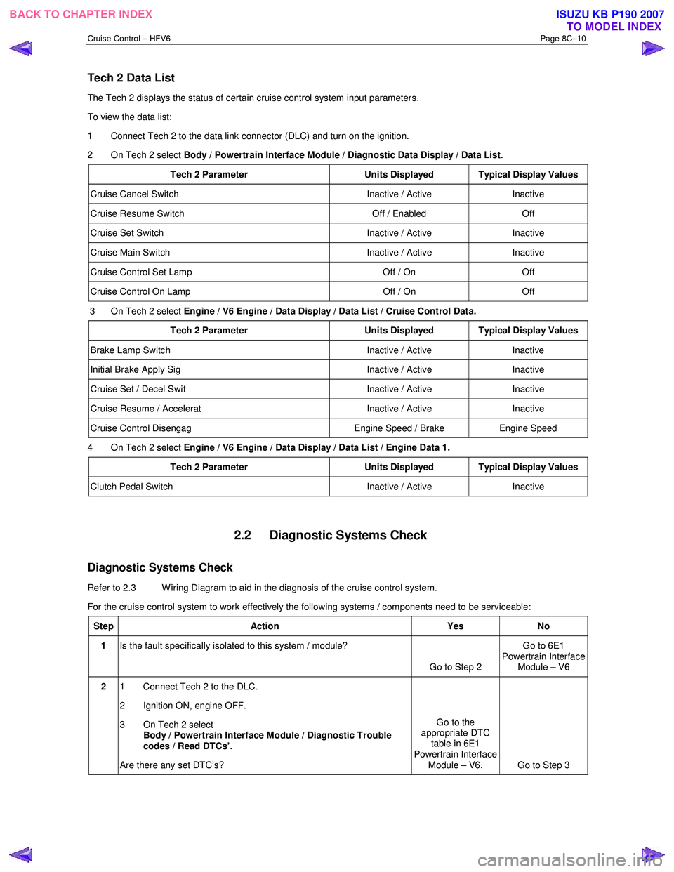
Tech 2 Data List
The Tech 2 displays the status of certain cruise control system input parameters.
To view the data list:
1 Connect Tech 2 to the data link connector (DLC) and turn on the ignition.
2 On Tech 2 select Body / Powertrain Interface Module / Diagnostic Data Display / Data List .
Tech 2 Parameter Units Displayed Typical Display Values
Cruise Cancel Switch Inactive / Active Inactive
Cruise Resume Switch Off / Enabled Off
Cruise Set Switch Inactive / Active Inactive
Cruise Main Switch Inactive / Active Inactive
Cruise Control Set Lamp Off / On Off
Cruise Control On Lamp Off / On Off
3 On Tech 2 select Engine / V6 Engine / Data Display / Data List / Cruise Control Data.
Tech 2 Parameter Units Displayed Typical Display Values
Brake Lamp Switch Inactive / Active Inactive
Initial Brake Apply Sig Inactive / Active Inactive
Cruise Set / Decel Swit Inactive / Active Inactive
Cruise Resume / Accelerat Inactive / Active Inactive
Cruise Control Disengag Engine Speed / Brake Engine Speed
4 On Tech 2 select Engine / V6 Engine / Data Display / Data List / Engine Data 1.
Tech 2 Parameter Units Displayed Typical Display Values
Clutch Pedal Switch Inactive / Active Inactive
2.2 Diagnostic Systems Check
Diagnostic Systems Check
Refer to 2.3 Wiring Diagram to aid in the diagnosis of the cruise control system.
For the cruise control system to work effectively the following systems / components need to be serviceable:
Step Action Yes No
1 Is the fault specifically isolated to this system / module?
Go to Step 2 Go to 6E1
Powertrain Interface Module – V6
2 1 Connect Tech 2 to the DLC.
2 Ignition ON, engine OFF.
3 On Tech 2 select Body / Powertrain Interface Module / Diagnostic Trouble
codes / Read DTCs’.
Are there any set DTC’s? Go to the
appropriate DTC table in 6E1
Powertrain Interface Module – V6. Go to Step 3
BACK TO CHAPTER INDEX TO MODEL INDEXISUZU KB P190 2007
Page 5592 of 6020
Cruise Control – HFV6 Page 8C–14
2.4 Cruise Control Inoperative /
Malfunctioning
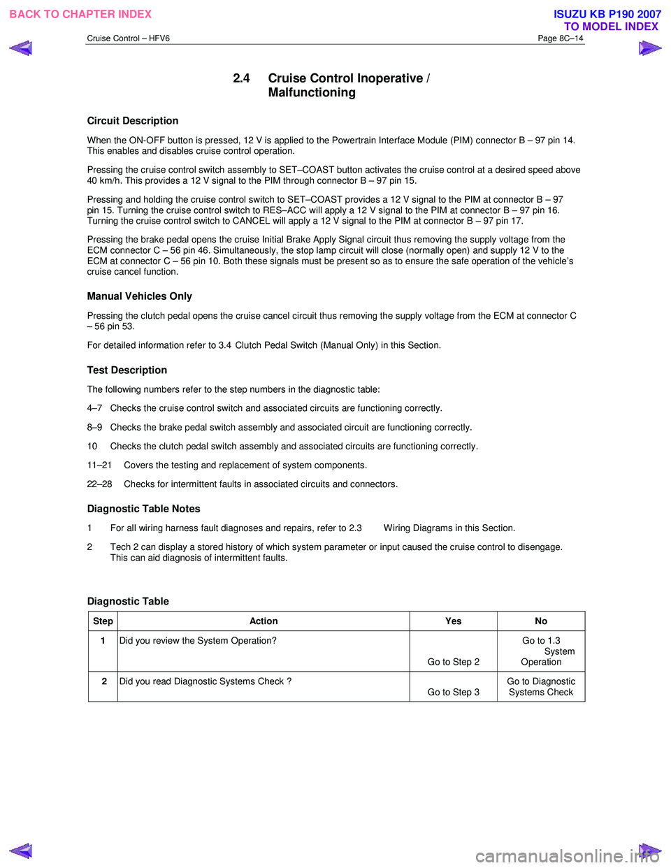
Circuit Description
When the ON-OFF button is pressed, 12 V is applied to the Powertrain Interface Module (PIM) connector B – 97 pin 14.
This enables and disables cruise control operation.
Pressing the cruise control switch assembly to SET–COAST button activates the cruise control at a desired speed above
40 km/h. This provides a 12 V signal to the PIM through connector B – 97 pin 15.
Pressing and holding the cruise control switch to SET–COAST provides a 12 V signal to the PIM at connector B – 97
pin 15. Turning the cruise control switch to RES–ACC will apply a 12 V signal to the PIM at connector B – 97 pin 16.
Turning the cruise control switch to CANCEL will apply a 12 V signal to the PIM at connector B – 97 pin 17.
Pressing the brake pedal opens the cruise Initial Brake Apply Signal circuit thus removing the supply voltage from the
ECM connector C – 56 pin 46. Simultaneously, the stop lamp circuit will close (normally open) and supply 12 V to the
ECM at connector C – 56 pin 10. Both these signals must be present so as to ensure the safe operation of the vehicle’s
cruise cancel function.
Manual Vehicles Only
Pressing the clutch pedal opens the cruise cancel circuit thus removing the supply voltage from the ECM at connector C
– 56 pin 53.
For detailed information refer to 3.4 Clutch Pedal Switch (Manual Only) in this Section.
Test Description
The following numbers refer to the step numbers in the diagnostic table:
4–7 Checks the cruise control switch and associated circuits are functioning correctly.
8–9 Checks the brake pedal switch assembly and associated circuit are functioning correctly.
10 Checks the clutch pedal switch assembly and associated circuits are functioning correctly.
11–21 Covers the testing and replacement of system components.
22–28 Checks for intermittent faults in associated circuits and connectors.
Diagnostic Table Notes
1 For all wiring harness fault diagnoses and repairs, refer to 2.3 W iring Diagrams in this Section.
2 Tech 2 can display a stored history of which system parameter or input caused the cruise control to disengage. This can aid diagnosis of intermittent faults.
Diagnostic Table
Step Action Yes No
1 Did you review the System Operation?
Go to Step 2 Go to 1.3
System Operation
2 Did you read Diagnostic Systems Check ?
Go to Step 3 Go to Diagnostic
Systems Check
BACK TO CHAPTER INDEX TO MODEL INDEXISUZU KB P190 2007
Page 5593 of 6020
Cruise Control – HFV6 Page 8C–15
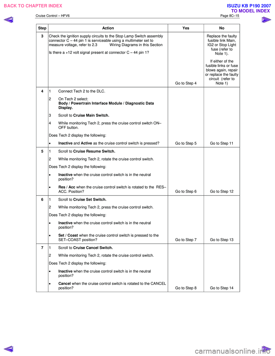
Step Action Yes No
3 Check the ignition supply circuits to the Stop Lamp Switch assembly
connector C – 44 pin 1 is serviceable using a multimeter set to
measure voltage, refer to 2.3 W iring Diagrams in this Section
Is there a +12 volt signal present at connector C – 44 pin 1?
Go to Step 4 Replace the faulty
fusible link Main,
IG2 or Stop Light fuse (refer to Note 1).
If either of the
fusible links or fuse blows again, repair
or replace the faulty circuit (refer to
Note 1)
4 1 Connect Tech 2 to the DLC.
2 On Tech 2 select: Body / Powertrain Interface Module / Diagnostic Data
Display.
3 Scroll to Cruise Main Switch.
4 W hile monitoring Tech 2, press the cruise control switch ON– OFF button.
Does Tech 2 display the following:
• Inactive and Active as the cruise control switch is pressed?
Go to Step 5 Go to Step 11
5 1 Scroll to Cruise Resume Switch.
2 While monitoring Tech 2, rotate the cruise control switch.
Does Tech 2 display the following:
• Inactive when the cruise control switch is in the neutral
position?
• Res / Acc when the cruise control switch is rotated to the RES–
ACC. Position? Go to Step 6 Go to Step 12
6
1 Scroll to Cruise Set Switch.
2 W hile monitoring Tech 2, press the cruise control switch.
Does Tech 2 display the following:
• Inactive when the cruise control switch is in the neutral
position?
• Set / Coast when the cruise control switch is pressed to the
SET–COAST position? Go to Step 7 Go to Step 13
7 1 Scroll to Cruise Cancel Switch.
2 While monitoring Tech 2, rotate the cruise control switch.
Does Tech 2 display the following:
• Inactive when the cruise control switch is in the neutral
position?
• Cancel when the cruise control switch is rotated to the CANCEL
position? Go to Step 8 Go to Step 14
BACK TO CHAPTER INDEX
TO MODEL INDEXISUZU KB P190 2007
Page 5594 of 6020
Cruise Control – HFV6 Page 8C–16
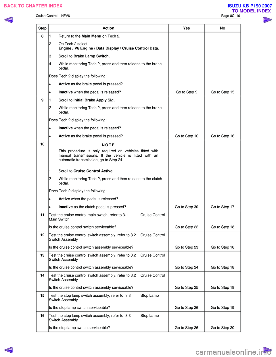
Step Action Yes No
8 1 Return to the Main Menu on Tech 2.
2 On Tech 2 select: Engine / V6 Engine / Data Display / Cruise Control Data.
3 Scroll to Brake Lamp Switch.
4 While monitoring Tech 2, press and then release to the brake pedal.
Does Tech 2 display the following:
• Active as the brake pedal is pressed?
• Inactive when the pedal is released? Go to Step 9 Go to Step 15
9 1 Scroll to Initial Brake Apply Sig.
2 While monitoring Tech 2, press and then release to the brake pedal.
Does Tech 2 display the following:
• Inactive when the pedal is released?
• Active as the brake pedal is pressed? Go to Step 10 Go to Step 16
10
NOTE
This procedure is only required on vehicles fitted with
manual transmissions. If the vehicle is fitted with an
automatic transmission, go to Step 24.
1 Scroll to Cruise Control Active .
2 While monitoring Tech 2, press and then release to the clutch pedal.
Does Tech 2 display the following:
• Active when the pedal is released?
• Inactive as the clutch pedal is pressed?
Go to Step 30 Go to Step 17
11 Test the cruise control main switch, refer to 3.1 Cruise Control
Main Switch
Is the cruise control switch serviceable? Go to Step 22 Go to Step 18
12 Test the cruise control switch assembly, refer to 3.2 Cruise Control
Switch Assembly
Is the cruise control switch assembly serviceable? Go to Step 23 Go to Step 18
13 Test the cruise control switch assembly, refer to 3.2 Cruise Control
Switch Assembly
Is the cruise control switch assembly serviceable? Go to Step 24 Go to Step 18
14 Test the cruise control switch assembly, refer to 3.2 Cruise Control
Switch Assembly
Is the cruise control switch assembly serviceable? Go to Step 25 Go to Step 18
15 Test the stop lamp switch assembly, refer to 3.3 Stop Lamp
Switch Assembly.
Is the stop lamp switch serviceable? Go to Step 26 Go to Step 19
16 Test the stop lamp switch assembly, refer to 3.3 Stop Lamp
Switch Assembly.
Is the stop lamp switch serviceable? Go to Step 26 Go to Step 20
BACK TO CHAPTER INDEX
TO MODEL INDEXISUZU KB P190 2007
Page 5595 of 6020
Cruise Control – HFV6 Page 8C–17
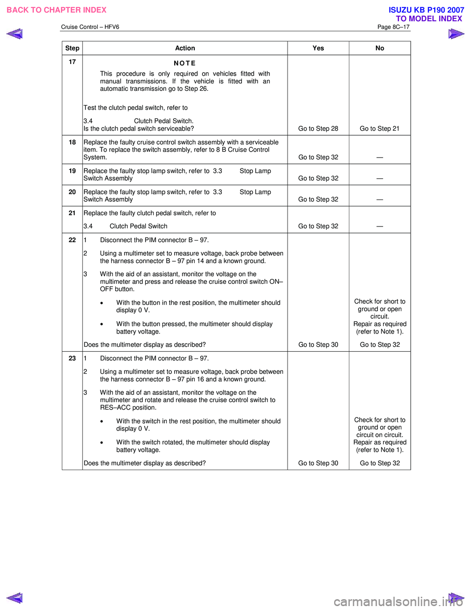
Step Action Yes No
17
NOTE
This procedure is only required on vehicles fitted with
manual transmissions. If the vehicle is fitted with an
automatic transmission go to Step 26.
Test the clutch pedal switch, refer to
3.4 Clutch Pedal Switch.
Is the clutch pedal switch serviceable? Go to Step 28 Go to Step 21
18 Replace the faulty cruise control switch assembly with a serviceable
item. To replace the switch assembly, refer to 8 B Cruise Control
System. Go to Step 32 —
19 Replace the faulty stop lamp switch, refer to 3.3 Stop Lamp
Switch Assembly Go to Step 32 —
20 Replace the faulty stop lamp switch, refer to 3.3 Stop Lamp
Switch Assembly Go to Step 32 —
21
Replace the faulty clutch pedal switch, refer to
3.4 Clutch Pedal Switch Go to Step 32 —
22 1 Disconnect the PIM connector B – 97.
2 Using a multimeter set to measure voltage, back probe between the harness connector B – 97 pin 14 and a known ground.
3 W ith the aid of an assistant, monitor the voltage on the multimeter and press and release the cruise control switch ON–
OFF button.
• W ith the button in the rest position, the multimeter should
display 0 V.
• W ith the button pressed, the multimeter should display
battery voltage.
Does the multimeter display as described? Go to Step 30 Check for short to
ground or open circuit.
Repair as required
(refer to Note 1).
Go to Step 32
23 1 Disconnect the PIM connector B – 97.
2 Using a multimeter set to measure voltage, back probe between the harness connector B – 97 pin 16 and a known ground.
3 With the aid of an assistant, monitor the voltage on the multimeter and rotate and release the cruise control switch to
RES–ACC position.
• With the switch in the rest position, the multimeter should
display 0 V.
• With the switch rotated, the multimeter should display
battery voltage.
Does the multimeter display as described? Go to Step 30 Check for short to
ground or open
circuit on circuit.
Repair as required
(refer to Note 1).
Go to Step 32
BACK TO CHAPTER INDEX TO MODEL INDEXISUZU KB P190 2007
Page 5596 of 6020
Cruise Control – HFV6 Page 8C–18
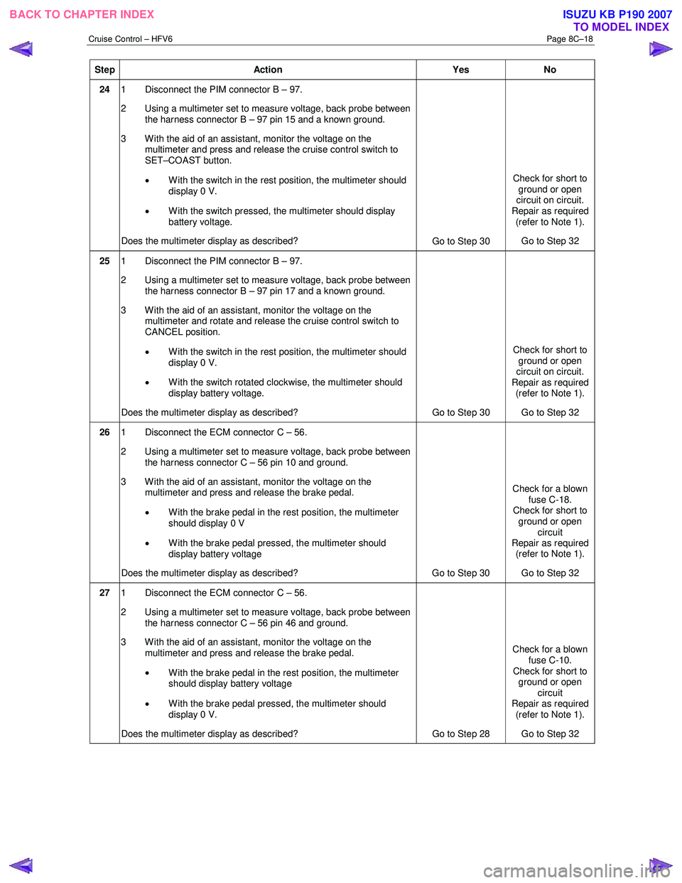
Step Action Yes No
24 1 Disconnect the PIM connector B – 97.
2 Using a multimeter set to measure voltage, back probe between the harness connector B – 97 pin 15 and a known ground.
3 With the aid of an assistant, monitor the voltage on the multimeter and press and release the cruise control switch to
SET–COAST button.
• With the switch in the rest position, the multimeter should
display 0 V.
• With the switch pressed, the multimeter should display
battery voltage.
Does the multimeter display as described? Go to Step 30 Check for short to
ground or open
circuit on circuit.
Repair as required (refer to Note 1).
Go to Step 32
25 1 Disconnect the PIM connector B – 97.
2 Using a multimeter set to measure voltage, back probe between the harness connector B – 97 pin 17 and a known ground.
3 W ith the aid of an assistant, monitor the voltage on the multimeter and rotate and release the cruise control switch to
CANCEL position.
• With the switch in the rest position, the multimeter should
display 0 V.
• W ith the switch rotated clockwise, the multimeter should
display battery voltage.
Does the multimeter display as described? Go to Step 30 Check for short to
ground or open
circuit on circuit.
Repair as required (refer to Note 1).
Go to Step 32
26 1 Disconnect the ECM connector C – 56.
2 Using a multimeter set to measure voltage, back probe between the harness connector C – 56 pin 10 and ground.
3 With the aid of an assistant, monitor the voltage on the multimeter and press and release the brake pedal.
• W ith the brake pedal in the rest position, the multimeter
should display 0 V
• W ith the brake pedal pressed, the multimeter should
display battery voltage
Does the multimeter display as described? Go to Step 30 Check for a blown
fuse C-18.
Check for short to
ground or open circuit
Repair as required (refer to Note 1).
Go to Step 32
27 1 Disconnect the ECM connector C – 56.
2 Using a multimeter set to measure voltage, back probe between the harness connector C – 56 pin 46 and ground.
3 With the aid of an assistant, monitor the voltage on the multimeter and press and release the brake pedal.
• W ith the brake pedal in the rest position, the multimeter
should display battery voltage
• W ith the brake pedal pressed, the multimeter should
display 0 V.
Does the multimeter display as described? Go to Step 28 Check for a blown
fuse C-10.
Check for short to ground or open
circuit
Repair as required (refer to Note 1).
Go to Step 32
BACK TO CHAPTER INDEX TO MODEL INDEXISUZU KB P190 2007
Page 5597 of 6020
Cruise Control – HFV6 Page 8C–19
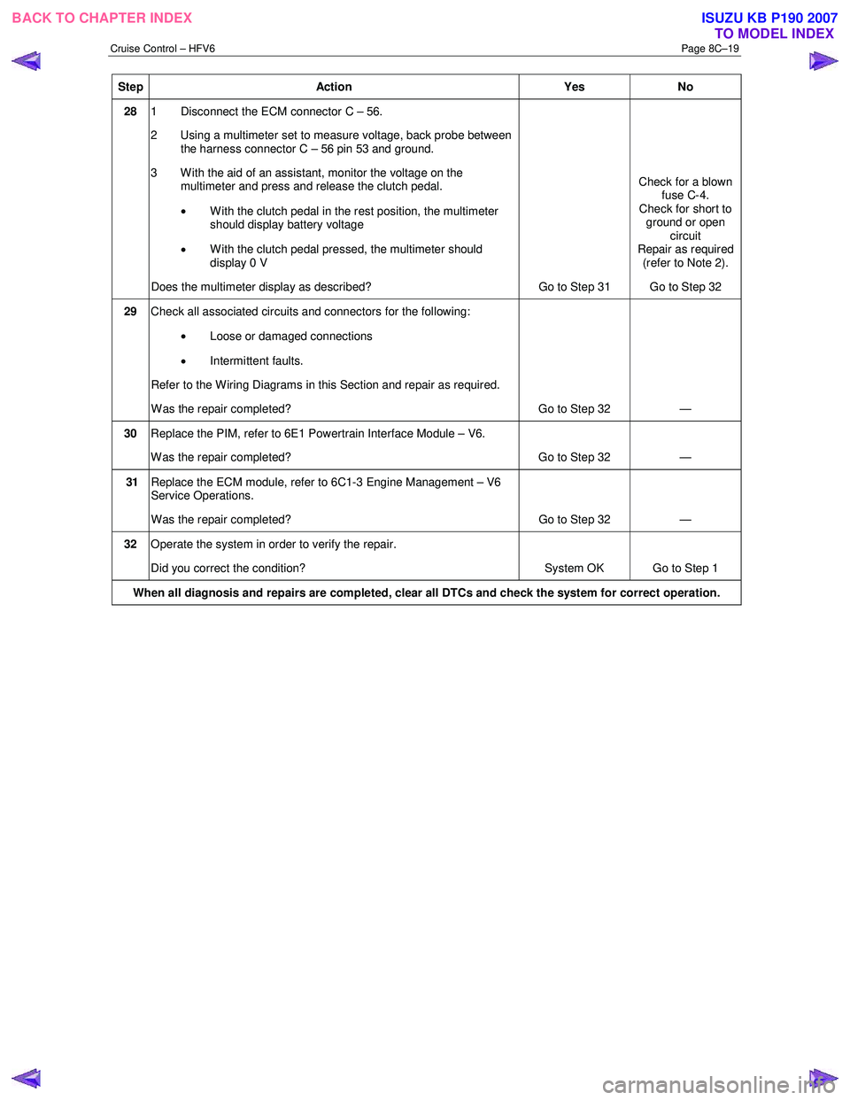
Step Action Yes No
28 1 Disconnect the ECM connector C – 56.
2 Using a multimeter set to measure voltage, back probe between the harness connector C – 56 pin 53 and ground.
3 W ith the aid of an assistant, monitor the voltage on the multimeter and press and release the clutch pedal.
• With the clutch pedal in the rest position, the multimeter
should display battery voltage
• W ith the clutch pedal pressed, the multimeter should
display 0 V
Does the multimeter display as described? Go to Step 31 Check for a blown
fuse C-4.
Check for short to ground or open circuit
Repair as required (refer to Note 2).
Go to Step 32
29 Check all associated circuits and connectors for the following:
• Loose or damaged connections
• Intermittent faults.
Refer to the Wiring Diagrams in this Section and repair as required.
W as the repair completed? Go to Step 32 —
30 Replace the PIM, refer to 6E1 Powertrain Interface Module – V6.
W as the repair completed? Go to Step 32 —
31 Replace the ECM module, refer to 6C1-3 Engine Management – V6
Service Operations.
W as the repair completed? Go to Step 32 —
32 Operate the system in order to verify the repair.
Did you correct the condition? System OK Go to Step 1
When all diagnosis and repairs are completed, clear all DTCs and check the system for correct operation.
BACK TO CHAPTER INDEX
TO MODEL INDEXISUZU KB P190 2007
Page 5649 of 6020
9A-14 SUPPLEMENTAL RESTRAINT SYSTEM
Component Description
SRS Control Unit
WARNING: DURING SERVICE PROCEDURES, BE
VERY CAREFUL WHEN HANDLING A SRS
CONTROL UNIT. NEVER STRIKE OR JAR THE SRS
CONTORL UNIT. NEVER POWER UP THE SRS
WHEN THE SRS CONTROL UNIT IS NOT RIGIDLY
ATTACHED TO THE VEHICLE. ALL SRS CONTROL
UNIT AND MOUNTING BRACKET FASTENERS
MUST BE CAREFULLY TORQUED AND THE
ARROW MUST BE POINTED TOWARD THE FRONT
OF THE VEHICLE TO ENSURE PROPER
OPERATION OF THE SRS. THE SRS CONTROL
UNIT COULD BE ACTIVATED WHEN POWERED
WHILE NOT RIGIDLY ATTACHED TO THE
VEHICLE WHICH COULD CAUSE DEPLOYMENT
AND RESULT IN PERSONAL INJURY.
The SRS control unit is designed to perform the
following functions in the SRS:
1. Energy Reserve — The SRS control unit maintains 30–Volt Loop Reserve (30VLR) energy supply to
provide deployment energy when ignition voltage is
lost in a frontal crash.
2. Frontal Crash Detection — The SRS control unit monitors vehicle velocity changes to detect frontal
crashes which are severe enough to warrant
deployment.
3. Air Bag Deployment — W hen a frontal crash o
f
sufficient force is detected, the SRS control unit
will cause enough current to flow through the ai
r
bag assembly to deploy the air bag.
4. Malfunction Detection — The SRS control unit performs diagnostic monitoring of SRS electrical
components and sets a diagnostic trouble code
when a malfunction is detected.
5. Frontal Crash Recording — The SRS control unit records information regarding SRS status during
frontal crash.
6. Malfunction Diagnosis — The SRS control unit displays SRS diagnostic trouble codes and system
status information through the use of a scan tool.
7. Driver Notification — The SRS control unit warns the vehicle driver of SRS malfunctions b
y
controlling the “SRS” warning lamp.
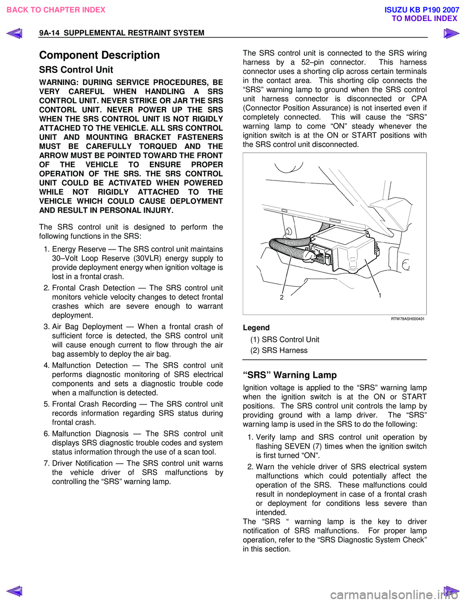
The SRS control unit is connected to the SRS wiring
harness by a 52–pin connector. This harness
connector uses a shorting clip across certain terminals
in the contact area. This shorting clip connects the
“SRS” warning lamp to ground when the SRS control
unit harness connector is disconnected or CP
A
(Connector Position Assurance) is not inserted even i
f
completely connected. This will cause the “SRS”
warning lamp to come “ON” steady whenever the
ignition switch is at the ON or START positions with
the SRS control unit disconnected.
RTW 79ASH000401
Legend
(1) SRS Control Unit
(2) SRS Harness
“SRS” Warning Lamp
Ignition voltage is applied to the “SRS” warning lamp
when the ignition switch is at the ON or START
positions. The SRS control unit controls the lamp b
y
providing ground with a lamp driver. The “SRS”
warning lamp is used in the SRS to do the following:
1. Verify lamp and SRS control unit operation b
y
flashing SEVEN (7) times when the ignition switch
is first turned “ON”.
2. W arn the vehicle driver of SRS electrical system malfunctions which could potentially affect the
operation of the SRS. These malfunctions could
result in nondeployment in case of a frontal crash
or deployment for conditions less severe than
intended.
The “SRS “ warning lamp is the key to drive
r
notification of SRS malfunctions. For proper lamp
operation, refer to the “SRS Diagnostic System Check”
in this section.
BACK TO CHAPTER INDEX TO MODEL INDEXISUZU KB P190 2007