Page 4963 of 6020

ELECTRICAL-BODY AND CHASSIS 8A-25
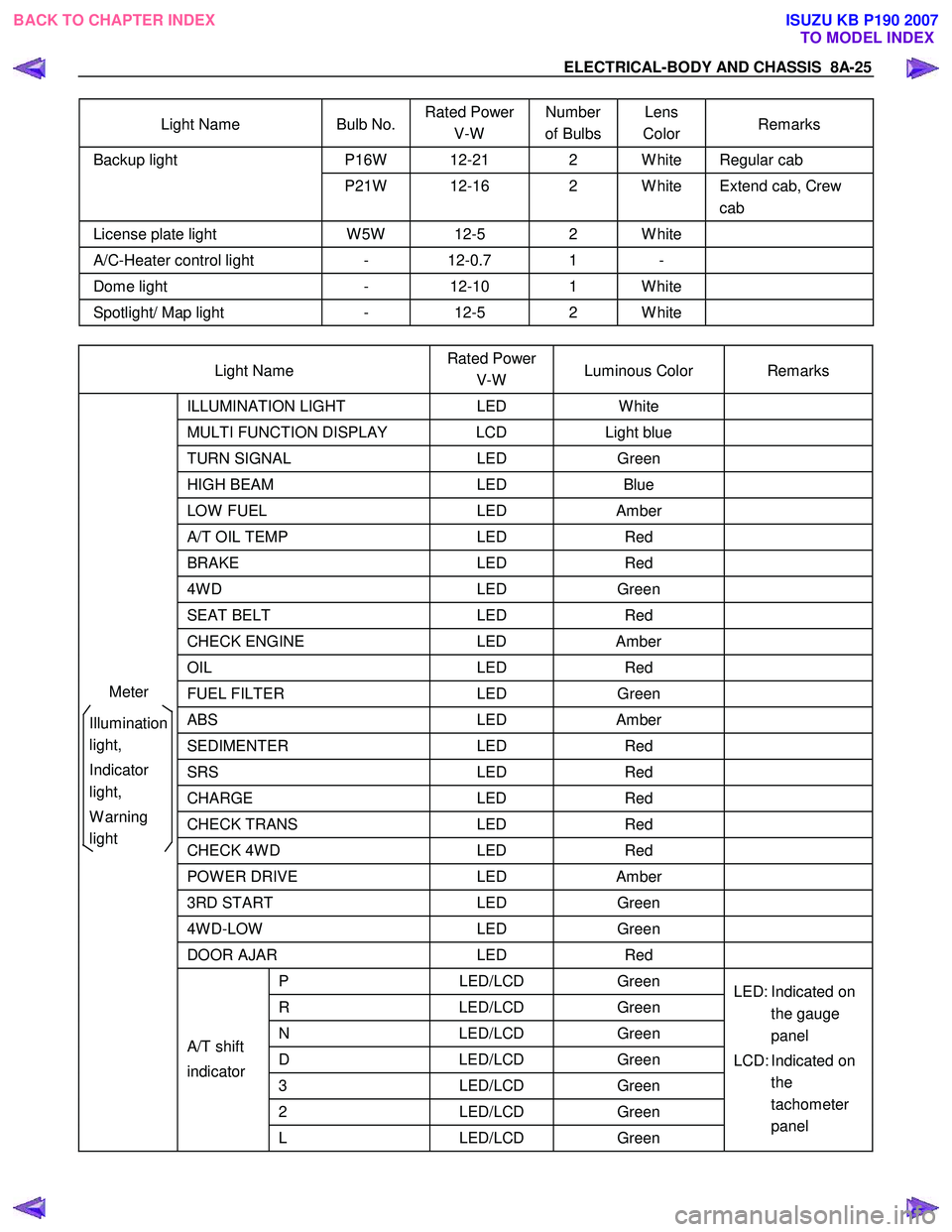
Light Name Bulb No. Rated Power
V-W Number
of Bulbs Lens
Color Remarks
P16W 12-21 2 W hite Regular cab Backup light
P21W 12-16 2 W hite Extend cab, Crew cab
License plate light W 5W 12-5 2 W hite
A/C-Heater control light - 12-0.7 1 -
Dome light - 12-10 1 W hite
Spotlight/ Map light - 12-5 2 W hite
Light Name Rated Power
V-W Luminous Color Remarks
ILLUMINATION
LIGHT LED W hite
MULTI FUNCTION DISPLAY LCD Light blue
TURN SIGNAL LED Green
HIGH BEAM LED Blue
LOW FUEL LED Amber
A/T OIL TEMP LED Red
BRAKE LED Red
4W D LED Green
SEAT BELT LED Red
CHECK ENGINE LED Amber
OIL LED Red
FUEL FILTER LED Green
ABS LED Amber
SEDIMENTER LED Red
SRS LED Red
CHARGE LED Red
CHECK TRANS LED Red
CHECK 4W D LED Red
POW ER DRIVE LED Amber
3RD START LED Green
4W D-LOW LED Green
DOOR AJAR LED Red
P LED/LCD Green
R LED/LCD Green
N LED/LCD Green
D LED/LCD Green
3 LED/LCD Green
2 LED/LCD Green
A/T shift
indicator
L LED/LCD Green LED: Indicated on
the gauge
panel
LCD: Indicated on the
tachometer
panel
Meter
Illumination
light,
Indicator
light,
W arning
light
BACK TO CHAPTER INDEX TO MODEL INDEXISUZU KB P190 2007
Page 5520 of 6020
8A-582 ELECTRICAL-BODY AND CHASSIS
060R100102
Operating Procedure
The power up screen is displayed when you power up
the tester with the Isuzu systems PCMCIA card.
Follow the operating procedure.
BACK TO CHAPTER INDEX TO MODEL INDEXISUZU KB P190 2007
Page 5522 of 6020
8A-584 ELECTRICAL-BODY AND CHASSIS
RTW 38DLH000101
Menu
The left table shows witch functions are used for the
available equipment versions.
NOTE: Marked items are not applied for keyless entry
system.
DTC
On OBD has three options available in the Tech-2
DTC mode to display the enhanced information
available.
• Read DTC Info Ordered By Priority.
• Read DTC Info As Stored By ECU.
• Clear DTC and Alarm Code Info.
Clear DTC Information
To clear Diagnostic Trouble Codes (DTCs), Use the
diagnostic scan tool “Clear DTC Information” function.
Tech-2 Data Display
The Tech-2 data values represent values that would
be seen on a normally-keyless entry system.
RTW 38DSH001601
Actuator Test
Unlock/Lock Test
Check whether opening and closing of a door lock
can be performed by operation of Tech-2.
1. Turn the key “OFF”.
2. Turn the key “ON”.
3. Check the display and test menu.
4. Operate the Tech-2.
BACK TO CHAPTER INDEX TO MODEL INDEXISUZU KB P190 2007
Page 5523 of 6020
ELECTRICAL-BODY AND CHASSIS 8A-585
RTW 38DSH001701
Turn Signal Test
Check the turn signal lamp lights up by operation of
Tech-2.
1. Turn the key “OFF”.
2. Turn the key “ON”.
3. Check the display and test menu.
4. Operate the Tech-2.
060R200289
Programming
Erase Remove Key
To erase remove control key code in the control unit.
1. Check the display of Tech-2 and press “Confirm”
key.
RTW 38DSH001001
2. Enter security code.
3. Press “Not Okay” or “Okay” key.
BACK TO CHAPTER INDEX TO MODEL INDEXISUZU KB P190 2007
Page 5524 of 6020
8A-586 ELECTRICAL-BODY AND CHASSIS
RTW 38DSH001101
4. Check the display of Tech-2 and press “Confirm”
key.
RTW 38DSH001201
5. Check the display of Tech-2 and press “Confirm”
key.
060R200289
Program Remote Key
To program remote control key code in the control
unit.
1. Check the display of Tech-2 and press “Confirm”
key.
BACK TO CHAPTER INDEX TO MODEL INDEXISUZU KB P190 2007
Page 5525 of 6020
ELECTRICAL-BODY AND CHASSIS 8A-587
RTW 38DSH001301
2. Check the following table in the display of Tech-2.
3. Operate the remote key.
RTW 38DSH001401
4. Check the display of Tech-2 and press “Confirm”
key.
RTW 38DSH001501
5. Check the display of Tech-2 and press “No” or
“Yes” key.
BACK TO CHAPTER INDEX TO MODEL INDEXISUZU KB P190 2007
Page 5583 of 6020

Cruise Control – HFV6 Page 8C–5
Legend
1 Engine Control Module
2 Throttle Actuator Control (TAC) Assembly
3 Cruise Control Switch Assembly
4 Instrument Cluster Assembly 5 Cruise Control ON / OFF Switch
6 Powertrain Interface Module
7 Clutch Pedal Switch Assembly (Manual Only)
8 Stop Lamp Switch Assembly
Cruise Control Switch Assembly
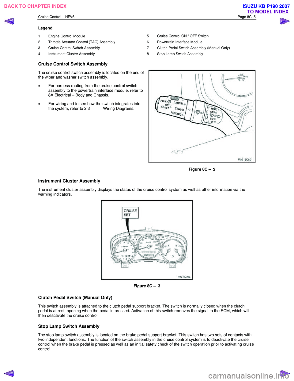
The cruise control switch assembly is located on the end of
the wiper and washer switch assembly.
• For harness routing from the cruise control switch
assembly to the powertrain interface module, refer to
8A Electrical – Body and Chassis.
• For wiring and to see how the switch integrates into
the system, refer to 2.3 W iring Diagrams.
Figure 8C – 2
Instrument Cluster Assembly
The instrument cluster assembly displays the status of the cruise control system as well as other information via the
warning indicators.
Figure 8C – 3
Clutch Pedal Switch (Manual Only)
This switch assembly is attached to the clutch pedal support bracket. The switch is normally closed when the clutch
pedal is at rest, opening when the pedal is pressed. Activation of this switch removes the signal to the ECM, which will
then deactivate the cruise control.
Stop Lamp Switch Assembly
The stop lamp switch assembly is located on the brake pedal support bracket. This switch has two sets of contacts with
two independent functions. The function of the switch assembly in the cruise control system is to deactivate the cruise
control when the brake pedal is pressed as well as an initial safety check of the switch operation prior to activating cruise
control.
BACK TO CHAPTER INDEX TO MODEL INDEXISUZU KB P190 2007
Page 5584 of 6020

Cruise Control – HFV6 Page 8C–6
The stop lamp switch contacts are normally open with the brake pedal at rest and close when the brake pedal is pressed
turning on the vehicles brake lamps. These switch contacts also double as the cruise cancel signal for the cruise control
operation.
The cruise control initial brake apply signal function switch contacts are normally closed with the brake pedal at rest and
open when the brake pedal is pressed. This switch function is a safety requirement of the vehicle as it ensures that the
cruise control cannot be activated without the brake pedal first being pressed.
Powertrain Interface Module
The Powertrain Interface Module (PIM) is located on the driver’s side, kick trim panel. The purpose of the PIM is to act as
an interface between the drivetrain serial data bus (GMLAN protocol) and the body side data bus (UART Bus protocol).
All inputs from the cruise control switch assembly are directly wired to the PIM. The PIM then takes these inputs,
converts them to GMLAN protocol and sends the messages via the data bus to the engine control module (ECM). The
PIM also receives signals for the cruise control system from the ECM. When the ECM activates cruise control, it sends a
signal through the PIM (which converts it from GMLAN to UART protocol) to display the various cruise control messages
on the instrument cluster assembly.
For further information on the operation of the PIM, refer to 6E1 Powertrain Interface Module – V6.
Engine Control Module
The Engine Control Module (ECM) is mounted on the front of the engine. The role of the ECM is to receive all the inputs
from various sensors (vehicle speed (VSS) etc.) and switches to manage the engine. W hen a request is sent from the
cruise control switch assembly via the PIM to the ECM, the ECM will activate cruise control providing given parameters
are satisfied. Once the cruise is set, the ECM monitors the vehicle speed and controls the throttle actuator assembly thus
controlling the speed of the vehicle.
For further information on the operation of the ECM, refer to 6C1-1 Engine Management – V6 – General Information.
Throttle Actuator Control (TAC) Assembly
The throttle actuator control assembly is located on the front of the inlet manifold. The throttle actuator control assembly
receives signals from the ECM and controls the angle of the throttle plate. Refer to 6C1-1 Engine Management – V6 –
General Information for further information.
1.3 System Operation
Preliminary Information
Enabled and Disabled
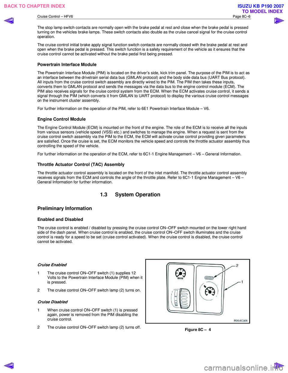
The cruise control is enabled / disabled by pressing the cruise control ON–OFF switch mounted on the lower right hand
side of the dash panel. When cruise control is enabled, the cruise control ON–OFF switch illuminates and the cruise
control is ready for a speed to be set (cruise control activated). W hen the cruise control is disabled, the cruise control
cannot be activated.
Cruise Enabled
1 The cruise control ON–OFF switch (1) supplies 12 Volts to the Powertrain Interface Module (PIM) when it
is pressed.
2 The cruise control ON–OFF switch lamp (2) turns on.
Cruise Disabled
1 W hen cruise control ON–OFF switch (1) is pressed again, power is removed from the PIM disabling the
cruise control.
2 The cruise control ON–OFF switch lamp (2) turns off.
Figure 8C – 4
BACK TO CHAPTER INDEX TO MODEL INDEXISUZU KB P190 2007