Page 4820 of 6020
7C-42 CLUTCH
TROUBLESHOOTING
Refer to this Section to quickly diagnose and repair clutch problems.
Each troubleshooting chart has three headings arranged from left to right. (1) Checkpoint (2) Trouble Cause (3) Countermeasure
This Section is divided into five sub-sections:
1. Clutch Slippage
2. Clutch Does Not Release Properly
3. Clutch Shudder
4. Clutch Noise 1) Clutch pedal Depressed (Clutch Disengaged)
2) Clutch pedal Not Depressed (Clutch Engaged)
5. Oil Leakage
BACK TO CHAPTER INDEX
TO MODEL INDEX
ISUZU KB P190 2007
Page 4821 of 6020
CLUTCH 7C-43
1. CLUTCH SLIPPAGE
Checkpoint Problem Countermeasure
Adjust the push rod play
No push rod play in the master
cylinder
NG
Clutch pedal free play
Clean the related parts and/or
replace the facing
Replace the transmission front
cover oil seal
Clean the related parts and/or
replace the facing
Repair or replace the
transmission front cover
Defective transmission front
cover oil seal
Continued on the next page
Grease or oil adhering to the
facing
Too much grease
Transmission front cover
unevenly worn
Release bearing
NG
NG
NG
OK
OK OK
BACK TO CHAPTER INDEX
TO MODEL INDEX
ISUZU KB P190 2007
Page 4822 of 6020
7C-44 CLUTCH
Checkpoint Problem Countermeasure
Replace the release bearingRelease bearing broken
Clean the related parts and/or
replace the facing
Replace the crankshaft rear oil
seal
Defective crankshaft rear oil
seal
NG
NG
OK
OKGrease or oil adhering to the
facing
Clutch diaphragm springReplace the clutch pressure
plate assemblyW eak or broken clutch
diaphragm spring
Replace the driven plate
assemblyWorn facing
NG
NG
OKFacing
Continued from the previous page
BACK TO CHAPTER INDEX
TO MODEL INDEX
ISUZU KB P190 2007
Page 4825 of 6020

CLUTCH 7C-47
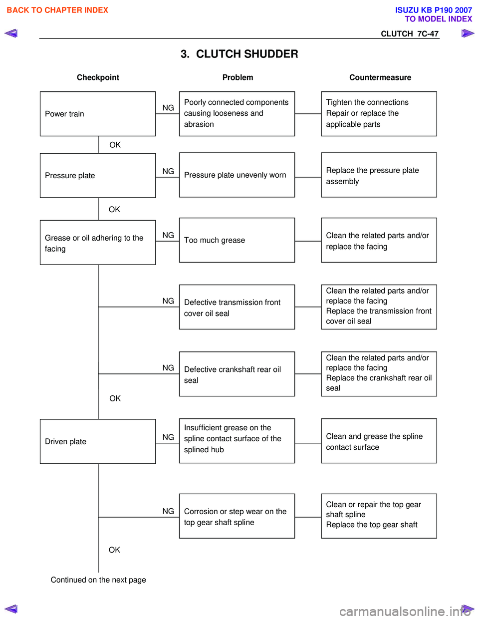
3. CLUTCH SHUDDER
Checkpoint Problem Countermeasure
Grease or oil adhering to the
facing
Clean the related parts and/or
replace the facing
Replace the transmission front
cover oil seal
Replace the pressure plate
assembly
Defective transmission front
cover oil seal
Pressure plate unevenly wornPressure plate
Clean the related parts and/or
replace the facing
Tighten the connections
Repair or replace the
applicable parts
Too much grease
Poorly connected components
causing looseness and
abrasion
OK
NG
NG
NG
NG
OK
Power train
Clean and grease the spline
contact surface
Insufficient grease on the
spline contact surface of the
splined hub
Driven plate
Clean or repair the top gear
shaft spline
Replace the top gear shaft
Clean the related parts and/or
replace the facing
Replace the crankshaft rear oil
seal
Corrosion or step wear on the
top gear shaft spline
Defective crankshaft rear oil
seal
OK NG
NG
NG
OK
Continued on the next page
BACK TO CHAPTER INDEX
TO MODEL INDEX
ISUZU KB P190 2007
Page 4828 of 6020
7C-50 CLUTCH
5. OIL LEAKAGE
Checkpoint Problem Countermeasure
Replace the body sub
assembly
W eak or damaged piston cup
NG
Tighten the oil pipe
Tighten the oil pipe connection
Tighten the fluid pipe and/or
hose connections
Fluid reservoir
Loosely connected oil pipe
Loosely connected oil pipe
Master cylinder fluid pipe and
hose
Loosely connected fluid pipe
and/or hose
Slave cylinder oil pipe
Replace the piston cup
Slave cylinder
W eak or damaged piston cup
NG
NG
NG
NG
OK
OK
OK
OK
Master cylinder
BACK TO CHAPTER INDEX
TO MODEL INDEX
ISUZU KB P190 2007
Page 4834 of 6020
7D-4 TRANSFER CASE
On-Vehicle Service
Transfer Case Oil Level
RTW 67DMF000101
Legend
(1) Transfer Case
(2) Filler Plug and O-ring
Removal
1. Disconnect the battery ground cable.
2. Rise and support the vehicle with suitable stands.
3. Remove the filler plug and O-ring.
4. Check the oil level reaches the filler hole.
5. If the oil level is low, fill the transfer oil (5W -30) o
r
equivalent to the transfer through the filler hole.
Installation
1. Replace the filler plug and O-ring tighten it to the
specified torque.
Filler plug torque: 39 N ⋅
⋅⋅
⋅
m (4.0 kgf ⋅
⋅⋅
⋅
m/29 lb ⋅
⋅⋅
⋅
ft)
2. Lower the vehicle to the ground.
3. Connect the battery ground cable.
BACK TO CHAPTER INDEX
TO MODEL INDEX
ISUZU KB P190 2007
Page 4857 of 6020

TRANSFER CASE 7D-27
Inspection and Repair
1. Make the necessary repair or parts replacement if
wear, damage or any other abnormal conditions are
found during inspection.
2. W ash all parts thoroughly in clean solvent. Be sure all
old lubricant, metallic particles, dirt, or foreign material
are removed from the surfaces of every part. Appl
y
compressed air to each oil feed port and channel in
each case half to remove any obstructions or cleaning
solvent residue.
Inspection and Repair (Transfer Case
Assembly)
W hen wear, damage, or any other defects are observed
during the inspection, the part or parts must be repaired
or replaced. W ash all the parts with clean detergent, and
check that old oil, metallic particles, dirt, or foreign
materials are completely removed. Blow the air into oil
holes and grooves to remove foreign materials or
residual detergent.
Chain
• Check whether the face that contacts the sprocket is
free from excessive wear or damage. If defects are
observed, replace the part.
• If the chain interference mark is found on the inside
wall of the transfer cover or the chain is so slack that a
skipped engagement occurs between the chain and
sprocket, replace the chain.
Sprocket
• Check whether the sprocket tooth surface is
excessively worn or damaged, and there is evidence
of burrs, chipping, wear, or damage on the gear
spline. Remove minor flaws or scratches with oil
stone. If excessive wear or damage is observed,
replace the part.
• If excessive wear or damage is observed on the
sprocket inside sliding surface, replace the part.
Gear
• Check whether the gear tooth surface is excessively
worn or damaged, and there is evidence of burrs,
chipping, wear, or damage on the gear spline.
• Remove minor flaws or scratches with oil stone. I
f
excessive wear or damage is observed, replace the
part.
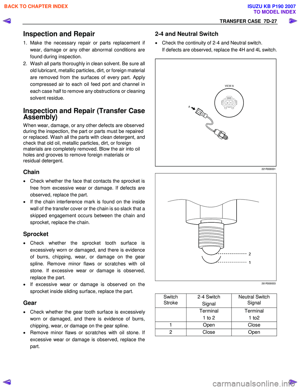
2-4 and Neutral Switch
• Check the continuity of 2-4 and Neutral switch.
If defects are observed, replace the 4H and 4L switch.
221R300001
261R300003
Switch
Stroke 2-4 Switch
Signal Neutral Switch
Signal
Terminal
1 to 2 Terminal
1 to2
1 Open Close
2 Close Open
BACK TO CHAPTER INDEX
TO MODEL INDEX
ISUZU KB P190 2007
Page 4858 of 6020

7D-28 TRANSFER CASE
Oil Pump
• Remove foreign materials from the strainer. If the
strainer is damaged, replace it.
If the area into which the shaft is inserted is excessively
worn or damaged, replace the oil pump assembly.
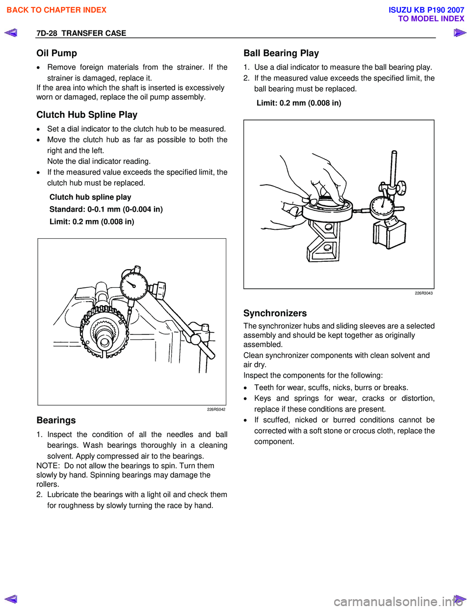
Clutch Hub Spline Play
• Set a dial indicator to the clutch hub to be measured.
• Move the clutch hub as far as possible to both the
right and the left.
Note the dial indicator reading.
• If the measured value exceeds the specified limit, the
clutch hub must be replaced.
Clutch hub spline play
Standard: 0-0.1 mm (0-0.004 in)
Limit: 0.2 mm (0.008 in)
226RS042
Bearings
1. Inspect the condition of all the needles and ball
bearings. W ash bearings thoroughly in a cleaning
solvent. Apply compressed air to the bearings.
NOTE: Do not allow the bearings to spin. Turn them
slowly by hand. Spinning bearings may damage the
rollers.
2. Lubricate the bearings with a light oil and check them
for roughness by slowly turning the race by hand.
Ball Bearing Play
1. Use a dial indicator to measure the ball bearing play.
2. If the measured value exceeds the specified limit, the
ball bearing must be replaced.
Limit: 0.2 mm (0.008 in)
226R3043
Synchronizers
The synchronizer hubs and sliding sleeves are a selected
assembly and should be kept together as originally
assembled.
Clean synchronizer components with clean solvent and
air dry.
Inspect the components for the following:
• Teeth for wear, scuffs, nicks, burrs or breaks.
• Keys and springs for wear, cracks or distortion,
replace if these conditions are present.
• If scuffed, nicked or burred conditions cannot be
corrected with a soft stone or crocus cloth, replace the
component.
BACK TO CHAPTER INDEX
TO MODEL INDEX
ISUZU KB P190 2007