Page 4515 of 6020
7A4-38 UNIT REPAIR (JR405E)
21R&H21
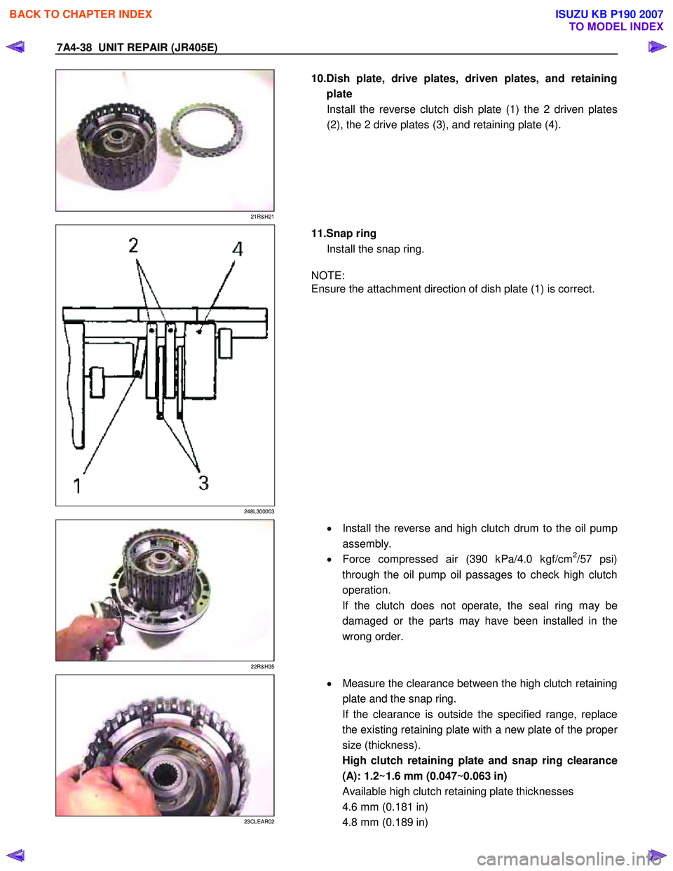
10.Dish plate, drive plates, driven plates, and retaining
plate Install the reverse clutch dish plate (1) the 2 driven plates
(2), the 2 drive plates (3), and retaining plate (4).
248L300003
11.Snap ring
Install the snap ring.
NOTE:
Ensure the attachment direction of dish plate (1) is correct.
22R&H35
•
Install the reverse and high clutch drum to the oil pump
assembly.
• Force compressed air (390 kPa/4.0 kgf/cm
2/57 psi)
through the oil pump oil passages to check high clutch
operation.
If the clutch does not operate, the seal ring may be
damaged or the parts may have been installed in the
wrong order.
23CLEAR02
•
Measure the clearance between the high clutch retaining
plate and the snap ring.
If the clearance is outside the specified range, replace
the existing retaining plate with a new plate of the prope
r
size (thickness).
High clutch retaining plate and snap ring clearance
(A): 1.2~1.6 mm (0.047~0.063 in)
Available high clutch retaining plate thicknesses
4.6 mm (0.181 in)
4.8 mm (0.189 in)
BACK TO CHAPTER INDEX
TO MODEL INDEX
ISUZU KB P190 2007
Page 4516 of 6020
UNIT REPAIR (JR405E) 7A4-39
248L300004
5.0 mm (0.197 in)
5.2 mm (0.205 in)
5.4 mm (0.213 in)
24R&H34
•
Force compressed air (390 kPa/4.0 kgf/cm2/57 psi)
through the oil pump oil passages to check reverse
clutch operation.
If the clutch does not operate, the seal ring may be
damaged or the parts may have been installed in the
wrong order.
BACK TO CHAPTER INDEX
TO MODEL INDEX
ISUZU KB P190 2007
Page 4523 of 6020
7A4-46 UNIT REPAIR (JR405E)
18C&L-SUB28
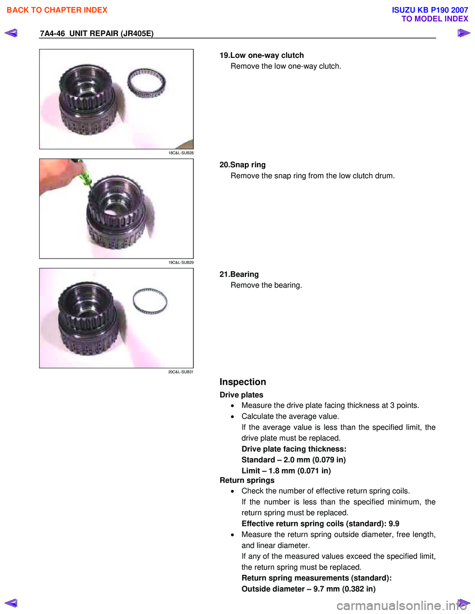
19.Low one-way clutch
Remove the low one-way clutch.
19C&L-SUB29
20.Snap ring
Remove the snap ring from the low clutch drum.
20C&L-SUB31
21.Bearing
Remove the bearing.
Inspection
Drive plates
• Measure the drive plate facing thickness at 3 points.
• Calculate the average value.
If the average value is less than the specified limit, the
drive plate must be replaced.
Drive plate facing thickness:
Standard – 2.0 mm (0.079 in)
Limit – 1.8 mm (0.071 in)
Return springs
• Check the number of effective return spring coils.
If the number is less than the specified minimum, the
return spring must be replaced.
Effective return spring coils (standard): 9.9
• Measure the return spring outside diameter, free length,
and linear diameter.
If any of the measured values exceed the specified limit,
the return spring must be replaced.
Return spring measurements (standard):
Outside diameter – 9.7 mm (0.382 in)
BACK TO CHAPTER INDEX
TO MODEL INDEX
ISUZU KB P190 2007
Page 4527 of 6020
7A4-50 UNIT REPAIR (JR405E)
34C&L-SUB15
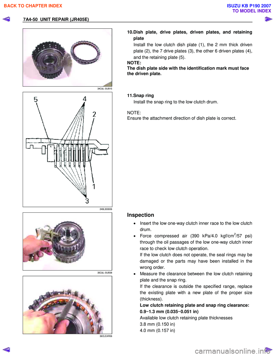
10.Dish plate, drive plates, driven plates, and retaining
plate Install the low clutch dish plate (1), the 2 mm thick driven
plate (2), the 7 drive plates (3), the other 6 driven plates (4),
and the retaining plate (5).
NOTE:
The dish plate side with the identification mark must face
the driven plate.
248L300006
11.Snap ring
Install the snap ring to the low clutch drum.
NOTE:
Ensure the attachment direction of dish plate is correct.
35C&L-SUB38
36CLEAR06
Inspection
• Insert the low one-way clutch inner race to the low clutch
drum.
• Force compressed air (390 kPa/4.0 kgf/cm
2/57 psi)
through the oil passages of the low one-way clutch inne
r
race to check low clutch operation.
If the low clutch does not operate, the seal rings may be
damaged or the parts may have been installed in the
wrong order.
• Measure the clearance between the low clutch retaining
plate and the snap ring.
If the clearance is outside the specified range, replace
the existing plate with a new plate of the proper size
(thickness).
Low clutch retaining plate and snap ring clearance:
0.9~1.3 mm (0.035~0.051 in)
Available low clutch retaining plate thicknesses
3.8 mm (0.150 in)
4.0 mm (0.157 in)
BACK TO CHAPTER INDEX
TO MODEL INDEX
ISUZU KB P190 2007
Page 4534 of 6020
UNIT REPAIR (JR405E) 7A4-57
11CASE-AY01
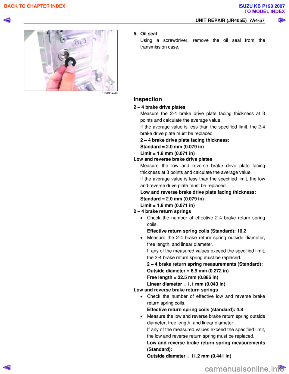
5. Oil seal
Using a screwdriver, remove the oil seal from the
transmission case.
Inspection
2 – 4 brake drive plates
Measure the 2-4 brake drive plate facing thickness at 3
points and calculate the average value.
If the average value is less than the specified limit, the 2-4
brake drive plate must be replaced.
2 – 4 brake drive plate facing thickness:
Standard = 2.0 mm (0.079 in)
Limit = 1.8 mm (0.071 in)
Low and reverse brake drive plates
Measure the low and reverse brake drive plate facing
thickness at 3 points and calculate the average value.
If the average value is less than the specified limit, the lo
w
and reverse drive plate must be replaced.
Low and reverse brake drive plate facing thickness:
Standard = 2.0 mm (0.079 in)
Limit = 1.8 mm (0.071 in)
2 – 4 brake return springs
• Check the number of effective 2-4 brake return spring
coils.
Effective return spring coils (Standard): 10.2
• Measure the 2-4 brake return spring outside diameter,
free length, and linear diameter.
If any of the measured values exceed the specified limit,
the 2-4 brake return spring must be replaced.
2 – 4 brake return spring measurements (Standard):
Outside diameter = 6.9 mm (0.272 in)
Free length = 22.5 mm (0.886 in)
Linear diameter = 1.1 mm (0.043 in)
Low and reverse brake return springs
• Check the number of effective low and reverse brake
return spring coils.
Effective return spring coils (standard): 4.8
• Measure the low and reverse brake return spring outside
diameter, free length, and linear diameter.
If any of the measured values exceed the specified limit,
the low and reverse return spring must be replaced.
Low and reverse brake return spring measurements
(Standard):
Outside diameter = 11.2 mm (0.441 in)
BACK TO CHAPTER INDEX
TO MODEL INDEX
ISUZU KB P190 2007
Page 4539 of 6020
7A4-62 UNIT REPAIR (JR405E)
RTW 37AMF0001-X
36ASSY10
•
Install the retaining plate (4).
37ASSY011
•
Install the snap ring.
38L&R03
•
Force compressed air (390 kPa/4.0 kgf/cm2/57 psi)
through the oil passages of the transmission case to
check low and reverse brake operation.
If the low and reverse brake does not operate, check the
seal rings for damage and replace if necessary. Also
check that no parts have been installed out of place.
BACK TO CHAPTER INDEX
TO MODEL INDEX
ISUZU KB P190 2007
Page 4647 of 6020
MANUAL TRANSMISSION 7B1-41
Clutch Hub Spline Play
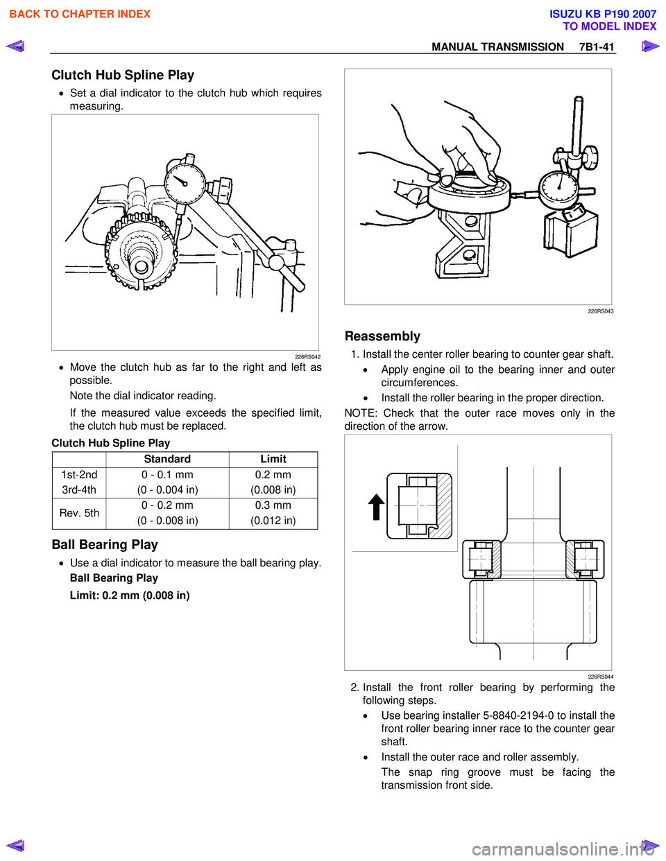
• Set a dial indicator to the clutch hub which requires
measuring.
226RS042
• Move the clutch hub as far to the right and left as
possible.
Note the dial indicator reading.
If the measured value exceeds the specified limit,
the clutch hub must be replaced.
Clutch Hub Spline Play
Standard Limit
1st-2nd 3rd-4th 0 - 0.1 mm
(0 - 0.004 in) 0.2 mm
(0.008 in)
Rev. 5th 0 - 0.2 mm
(0 - 0.008 in) 0.3 mm
(0.012 in)
Ball Bearing Play
• Use a dial indicator to measure the ball bearing play.
Ball Bearing Play
Limit: 0.2 mm (0.008 in)
226RS043
Reassembly
1. Install the center roller bearing to counter gear shaft.
•
Apply engine oil to the bearing inner and outer
circumferences.
• Install the roller bearing in the proper direction.
NOTE: Check that the outer race moves only in the
direction of the arrow.
226RS044
2. Install the front roller bearing by performing the following steps.
• Use bearing installer 5-8840-2194-0 to install the
front roller bearing inner race to the counter gea
r
shaft.
• Install the outer race and roller assembly.
The snap ring groove must be facing the
transmission front side.
BACK TO CHAPTER INDEX
TO MODEL INDEX
ISUZU KB P190 2007
Page 4651 of 6020
MANUAL TRANSMISSION 7B1-45
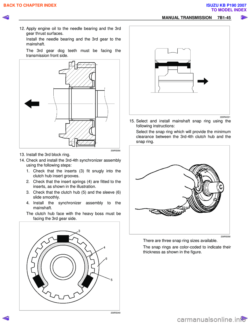
12. Apply engine oil to the needle bearing and the 3rd
gear thrust surfaces.
Install the needle bearing and the 3rd gear to the
mainshaft.
The 3rd gear dog teeth must be facing the
transmission front side.
226RS056
13. Install the 3rd block ring.
14. Check and install the 3rd-4th synchronizer assembl
y
using the following steps:
1. Check that the inserts (3) fit snugly into the clutch hub insert grooves.
2. Check that the insert springs (4) are fitted to the inserts, as shown in the illustration.
3. Check that the clutch hub (5) and the sleeve (6) slide smoothly.
4. Install the synchronizer assembly to the mainshaft.
The clutch hub face with the heavy boss must be facing the 3rd gear side.
226RS049
226RW 221
15. Select and install mainshaft snap ring using the
following instructions:
Select the snap ring which will provide the minimum
clearance between the 3rd-4th clutch hub and the
snap ring.
226RS058
There are three snap ring sizes available.
The snap rings are color-coded to indicate thei
r
thickness as shown in the figure.
BACK TO CHAPTER INDEX
TO MODEL INDEX
ISUZU KB P190 2007