2007 ISUZU KB P190 check oil
[x] Cancel search: check oilPage 4920 of 6020
7D1-46 TRANSFER CONTROL SYSTEM
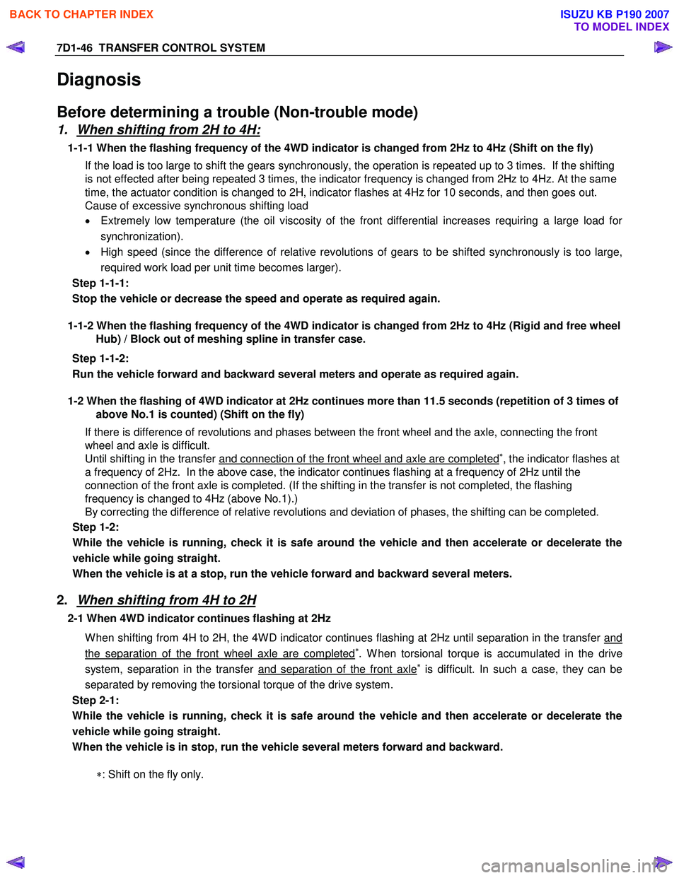
Diagnosis
Before determining a trouble (Non-trouble mode)
1. When shifting from 2H to 4H:
1-1-1 When the flashing frequency of the 4WD indicator is changed from 2Hz to 4Hz (Shift on the fly) If the load is too large to shift the gears synchronously, the operation is repeated up to 3 times. If the shifting
is not effected after being repeated 3 times, the indicator frequency is changed from 2Hz to 4Hz. At the same
time, the actuator condition is changed to 2H, indicator flashes at 4Hz for 10 seconds, and then goes out.
Cause of excessive synchronous shifting load
• Extremely low temperature (the oil viscosity of the front differential increases requiring a large load for
synchronization).
• High speed (since the difference of relative revolutions of gears to be shifted synchronously is too large,
required work load per unit time becomes larger).
Step 1-1-1:
Stop the vehicle or decrease the speed and operate as required again.
1-1-2 When the flashing frequency of the 4WD indicator is changed from 2Hz to 4Hz (Rigid and free wheel
Hub) / Block out of meshing spline in transfer case.
Step 1-1-2:
Run the vehicle forward and backward several meters and operate as required again.
1-2 When the flashing of 4WD indicator at 2Hz continues more than 11.5 seconds (repetition of 3 times of
above No.1 is counted) (Shift on the fly)
If there is difference of revolutions and phases between the front wheel and the axle, connecting the front
wheel and axle is difficult.
Until shifting in the transfer and connection of the front wheel and axle are completed
∗, the indicator flashes at
a frequency of 2Hz. In the above case, the indicator continues flashing at a frequency of 2Hz until the
connection of the front axle is completed. (If the shifting in the transfer is not completed, the flashing
frequency is changed to 4Hz (above No.1).)
By correcting the difference of relative revolutions and deviation of phases, the shifting can be completed.
Step 1-2:
While the vehicle is running, check it is safe around the vehicle and then accelerate or decelerate the
vehicle while going straight.
When the vehicle is at a stop, run the vehicle forward and backward several meters.
2. When shifting from 4H to 2H
2-1 When 4WD indicator continues flashing at 2Hz
W hen shifting from 4H to 2H, the 4W D indicator continues flashing at 2Hz until separation in the transfer and
the separation of the front wheel axle are completed∗. W hen torsional torque is accumulated in the drive
system, separation in the transfer and separation of the front axle∗ is difficult. In such a case, they can be
separated by removing the torsional torque of the drive system.
Step 2-1:
While the vehicle is running, check it is safe around the vehicle and then accelerate or decelerate the
vehicle while going straight.
When the vehicle is in stop, run the vehicle several meters forward and backward.
∗: Shift on the fly only.
BACK TO CHAPTER INDEX
TO MODEL INDEX
ISUZU KB P190 2007
Page 4963 of 6020
ELECTRICAL-BODY AND CHASSIS 8A-25
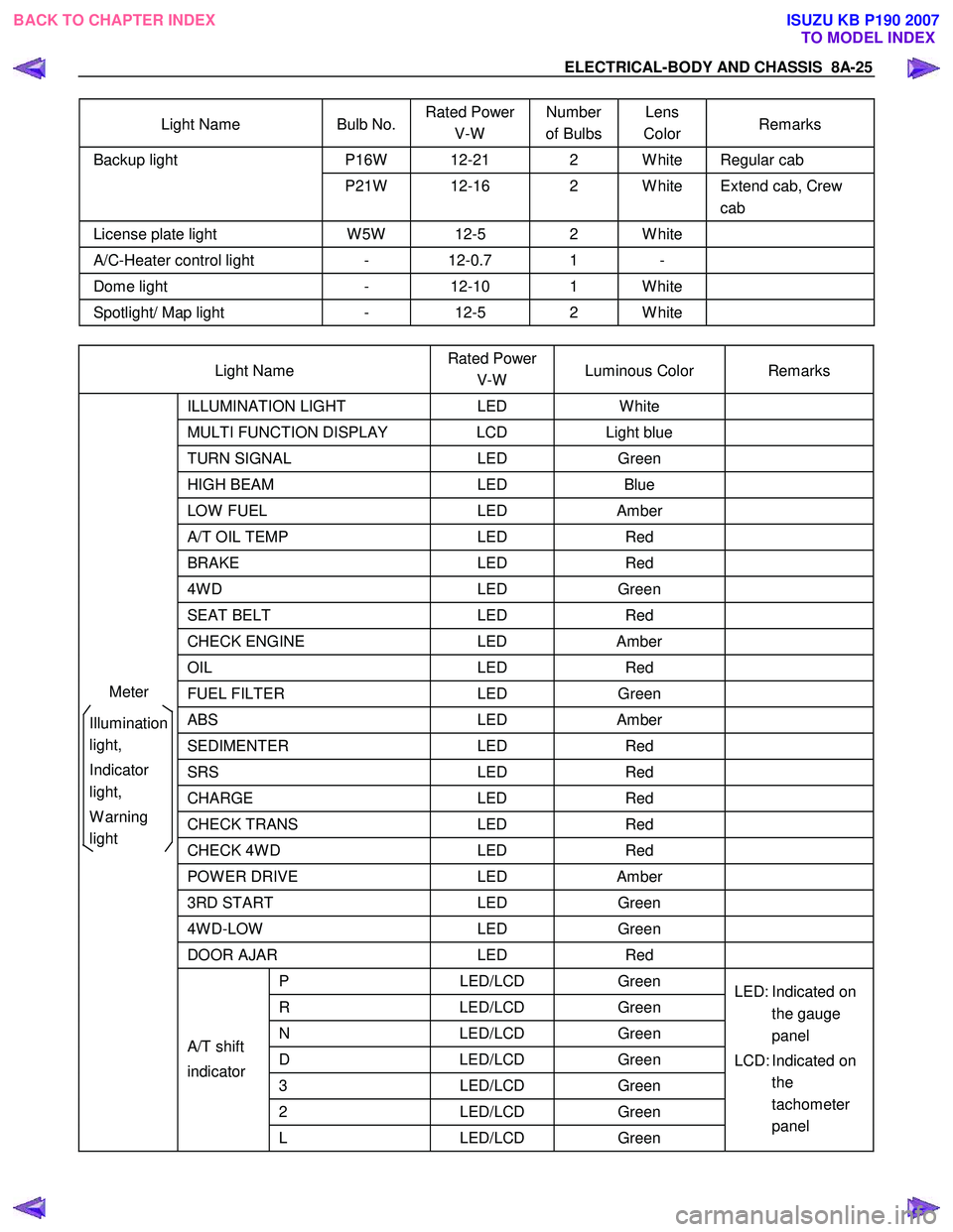
Light Name Bulb No. Rated Power
V-W Number
of Bulbs Lens
Color Remarks
P16W 12-21 2 W hite Regular cab Backup light
P21W 12-16 2 W hite Extend cab, Crew cab
License plate light W 5W 12-5 2 W hite
A/C-Heater control light - 12-0.7 1 -
Dome light - 12-10 1 W hite
Spotlight/ Map light - 12-5 2 W hite
Light Name Rated Power
V-W Luminous Color Remarks
ILLUMINATION
LIGHT LED W hite
MULTI FUNCTION DISPLAY LCD Light blue
TURN SIGNAL LED Green
HIGH BEAM LED Blue
LOW FUEL LED Amber
A/T OIL TEMP LED Red
BRAKE LED Red
4W D LED Green
SEAT BELT LED Red
CHECK ENGINE LED Amber
OIL LED Red
FUEL FILTER LED Green
ABS LED Amber
SEDIMENTER LED Red
SRS LED Red
CHARGE LED Red
CHECK TRANS LED Red
CHECK 4W D LED Red
POW ER DRIVE LED Amber
3RD START LED Green
4W D-LOW LED Green
DOOR AJAR LED Red
P LED/LCD Green
R LED/LCD Green
N LED/LCD Green
D LED/LCD Green
3 LED/LCD Green
2 LED/LCD Green
A/T shift
indicator
L LED/LCD Green LED: Indicated on
the gauge
panel
LCD: Indicated on the
tachometer
panel
Meter
Illumination
light,
Indicator
light,
W arning
light
BACK TO CHAPTER INDEX TO MODEL INDEXISUZU KB P190 2007
Page 5290 of 6020
8A-352 ELECTRICAL-BODY AND CHASSIS
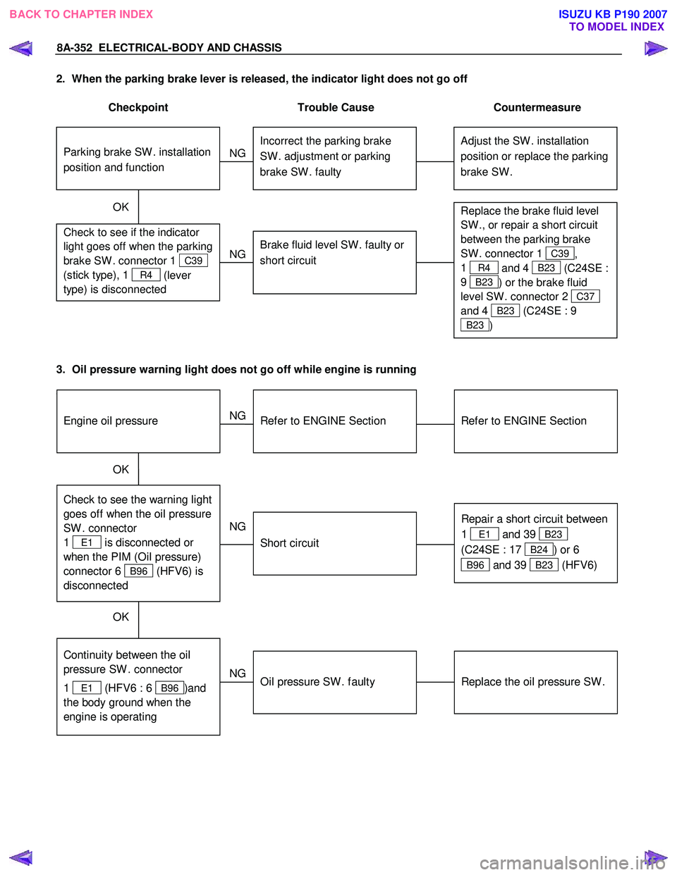
2. When the parking brake lever is released, the indicator light does not go off
Checkpoint Trouble Cause Countermeasure
Adjust the SW . installation
position or replace the parking
brake SW . Incorrect the parking brake
SW . adjustment or parking
brake SW . faulty
NG
Thermo unit malfunction
Replace the brake fluid level
SW ., or repair a short circuit
between the parking brake
SW . connector 1
C39,
1
R4 and 4 B23 (C24SE :
9
B23 ) or the brake fluid
level SW . connector 2
C37
and 4
B23 (C24SE : 9
B23 )
Check to see if the indicator
light goes off when the parking
brake SW . connector 1
C39
(stick type), 1
R4 (lever
type) is disconnected
Brake fluid level SW . faulty or
short circuit
NG
OK
Parking brake SW . installation
position and function
3. Oil pressure warning light does not go off while engine is running
Refer to ENGINE Section
Refer to ENGINE Section
NG Thermo unit malfunction
Check to see the warning light
goes off when the oil pressure
SW . connector
1
E1 is disconnected or
when the PIM (Oil pressure)
connector 6
B96 (HFV6) is
disconnected
Repair a short circuit between
1
E1 and 39 B23
(C24SE : 17
B24) or 6
B96 and 39 B23 (HFV6)
Short circuit
NG
OK
Replace the oil pressure SW .
Continuity between the oil
pressure SW . connector
1
E1 (HFV6 : 6 B96 )and
the body ground when the
engine is operating
Oil pressure SW . faulty
NG
OK
Engine oil pressure
BACK TO CHAPTER INDEX TO MODEL INDEXISUZU KB P190 2007
Page 5303 of 6020
ELECTRICAL-BODY AND CHASSIS 8A-365
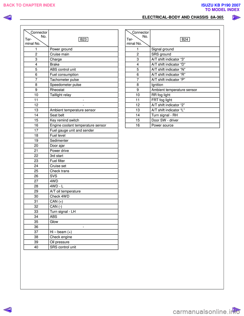
Connector
Ter- No.
minal No.
B23
1 Power ground
2 Cruise main
3 Charge
4 Brake
5 ABS control unit
6 Fuel consumption
7 Tachometer pulse
8 Speedometer pulse
9 Rheostat
10 Taillight relay
11 -
12 -
13 Ambient temperature sensor
14 Seat belt
15 Key remind switch
16 Engine coolant temperature sensor
17 Fuel gauge unit and sender
18 Fuel level
19 Sedimenter
20 Door ajar
21 Power drive
22 3rd start
23 Fuel filter
24 Cruise set
25 Check trans
26 SVS
27 4W D
28 4W D - L
29 A/T oil temperature
30 Check 4W D
31 CAN (+)
32 CAN (-)
33 Turn signal - LH
34 ABS
35 Glow
36 -
37 Hi – beam (+)
38 Check engine
39 Oil pressure
40 SRS control unit
Connector
Ter- No.
minal No.
B24
1 Signal ground
2 SRS ground
3 A/T shift indicator “3”
4 A/T shift indicator “D”
5 A/T shift indicator “N”
6 A/T shift indicator “R”
7 A/T shift indicator “P”
8 Ignition
9 Ambient temperature sensor
10 RR fog light
11 FRT fog light
12 A/T shift indicator “2”
13 A/T shift indicator “L”
14 Turn signal - RH
15 Door SW - driver
16 Power source
BACK TO CHAPTER INDEX TO MODEL INDEXISUZU KB P190 2007
Page 5304 of 6020
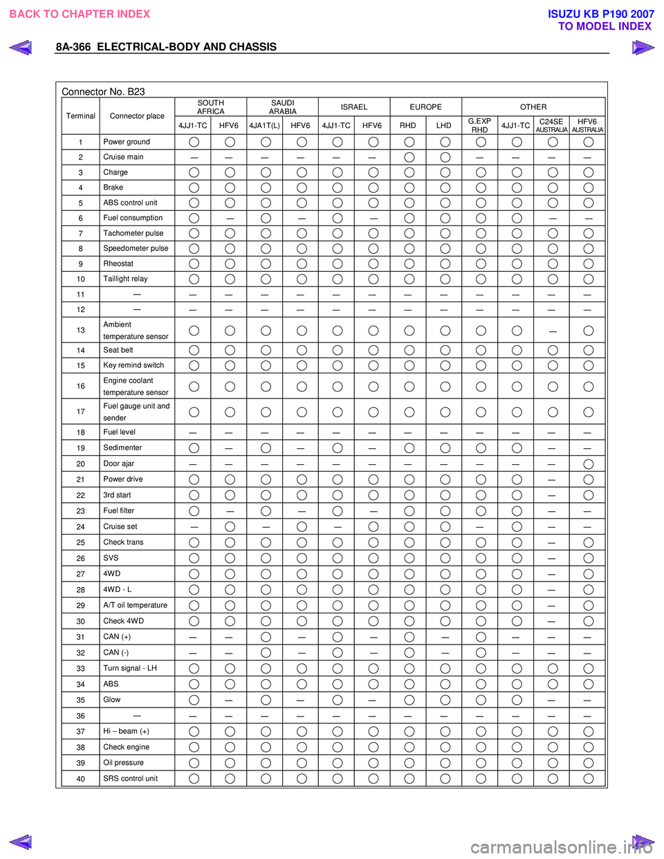
8A-366 ELECTRICAL-BODY AND CHASSIS
Connector No. B23 SOUTH
AFRICA SAUDI
ARABIA ISRAEL EUROPE OTHER
Terminal Connector place
4JJ1-TC HFV6 4JA1T(L) HFV6 4JJ1-TC HFV6 RHD LHD G.EXP
RHD 4JJ1-TC
C24SE
AUSTRALIAHFV6AUSTRALIA
1
Power ground
2 Cruise main
―
― ― ― ― ― ― ― ― ―
3
Charge
4 Brake
5 ABS control unit
6 Fuel consumption ―
―
―
―
―
7 Tachometer pulse
8 Speedometer pulse
9 Rheostat
10 Taillight relay
11 ―
― ― ― ― ― ― ― ― ― ― ― ―
12 ―
― ― ― ― ― ― ― ― ― ― ― ―
13 Ambient
temperature sensor ―
14 Seat belt
15 Key remind switch
16 Engine coolant
temperature sensor
17 Fuel gauge unit and
sender
18 Fuel level
― ― ― ― ― ― ― ― ― ― ― ―
19 Sedimenter ―
―
―
―
―
20 Door ajar
― ― ― ― ― ― ― ― ― ― ―
21 Power drive ―
22 3rd start ―
23 Fuel filter ―
―
―
―
―
24 Cruise set
― ―
―
―
―
―
25 Check trans ―
26 SVS ―
27 4W D ―
28 4W D - L ―
29 A/T oil temperature ―
30 Check 4W D ―
31 CAN (+)
― ― ―
―
―
― ― ―
32
CAN (-)
― ― ―
―
―
― ― ―
33
Turn signal - LH
34 ABS
35 Glow ―
―
―
―
―
36 ―
― ― ― ― ― ― ― ― ― ― ― ―
37 Hi – beam (+)
38 Check engine
39 Oil pressure
40 SRS control unit
BACK TO CHAPTER INDEX
TO MODEL INDEXISUZU KB P190 2007
Page 5427 of 6020
ELECTRICAL-BODY AND CHASSIS 8A-489
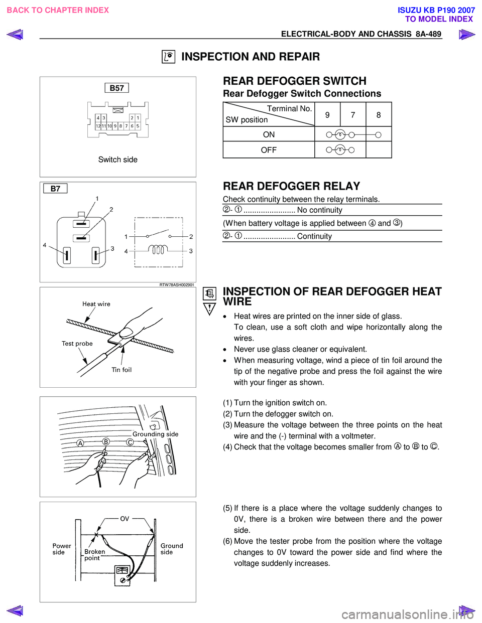
INSPECTION AND REPAIR
Switch side
B57
REAR DEFOGGER SWITCH
Rear Defogger Switch Connections
Terminal No.
SW position 9 7 8
ON
OFF
B7
RTW 78ASH002901
REAR DEFOGGER RELAY
Check continuity between the relay terminals.
2- 1........................ No continuity
(W hen battery voltage is applied between 4 and 3)
2- 1........................ Continuity
INSPECTION OF REAR DEFOGGER HEAT
WIRE
• Heat wires are printed on the inner side of glass.
To clean, use a soft cloth and wipe horizontally along the wires.
• Never use glass cleaner or equivalent.
• W hen measuring voltage, wind a piece of tin foil around the
tip of the negative probe and press the foil against the wire
with your finger as shown.
(1) Turn the ignition switch on.
(2) Turn the defogger switch on.
(3) Measure the voltage between the three points on the heat wire and the (-) terminal with a voltmeter.
(4) Check that the voltage becomes smaller from
A to B to C.
(5) If there is a place where the voltage suddenly changes to
0V, there is a broken wire between there and the powe
r
side.
(6) Move the tester probe from the position where the voltage changes to 0V toward the power side and find where the
voltage suddenly increases.
BACK TO CHAPTER INDEX TO MODEL INDEXISUZU KB P190 2007
Page 5652 of 6020
SUPPLEMENTAL RESTRAINT SYSTEM 9A-17
“Continuous Monitoring”
Tests are performed by the SRS control unit on the
SRS every 100 milliseconds while “Ignition 1” voltage
is in the normal operating voltage range at the SRS
control unit.
Data Link Connector (DLC)
Formerly “DLC”, a connector which allows
communication with an external computer, such as a
scan tool.
Datum Line
A base line parallel to the plane of the underbody or
frame from which all vertical measurements originate.
Deploy
To inflate the air bag.
Deployment Loops
The circuits which supply current to the air bag
assemblies to deploy the air bag.
Diagnostic Trouble Code (DTC)
Formerly “Code”, a numerical designator used by the
SRS control unit to indicate specific SRS malfunctions.
Driver Current Source
An output of the SRS control unit which applies current
into the driver air bag assembly circuit during the
“Initiator Assembly Resistance Test”.
Driver Air Bag Assembly
An assembly located in the steering wheel hub
consisting of an inflatable bag, an inflator and an
initiator.
EEPROM
Electrically Erasable Programmable Read Onl
y
Memory. Memory which retains its contents when
power is removed from the SRS control unit.
Ignition Cycle
The voltage at the SRS control unit “Ignition 1” input,
with ignition switch “ON”, is within the normal operating
voltage range for at least ten seconds before turning
the ignition switch “OFF”.
Ignition 1
A battery voltage (B+) circuit which is only powered
when the ignition switch is in the ON, or START
position.
Initiator
The electrical component inside the air bag assembl
y
which, when sufficient current flows, sets off the
chemical reaction that inflates the air bag.
“Initiator Assembly Resistance Test”
Tests are performed once for each ignition cycle when
no malfunctions are detected during “Turn–ON” o
r
“Continuous Monitoring”. This test checks for the
correct SRS control unit configuration for the vehicle,
shorts to “Ignition 1” in the deployment loops, high
resistance or opens in the “Driver Side” and
“Passenger Side” circuits and measures the resistance
of the inflator assembly consisting of 1) Initiators, 2)
SRS coil assembly (driver side only), 3) Connectors
and associated wiring.
Normal Operating Voltage Range
The voltage measured between the SRS control unit
“Ignition 1” terminals and “Ground” terminals is
between 9 and 16 volts.
Passenger Current Source
An output of the SRS control unit which applies current
into the passenger air bag assembly circuit during the
“Initiator Assembly Resistance Test”.
Passenger Air Bag Assembly
An assembly located in the front of the passenger side
of the instrument panel consisting of an inflatable bag,
an inflator and an initiator.
Scan Tool
An external computer used to read diagnostic
information from on–board computers via the data link
connector.
SRS control unit
SRS control unit which provides reserve energy to the
deployment loops, deploys the air bags when required
and performs diagnostic monitoring of all SRS
components.
Serial Data
Information representing the status of the SRS.
SRS
Supplemental Restraint System.
SRS Coil Assembly
An assembly of two current–carrying coils in the drive
r
deployment loop that allows the rotation of the steering
wheel while maintaining the continuous contact of the
driver deployment loop to the driver air bag assembly.
SRS Wiring Harness
The wires and connectors that electrically connect the
components in the SRS.
“Turn–ON”
Test which the SRS control unit performs on the SRS
once during each ignition cycle immediately afte
r
“Ignition 1” voltage is applied to the SRS control unit
and before “Continuous Monitoring”.
BACK TO CHAPTER INDEX TO MODEL INDEXISUZU KB P190 2007
Page 5668 of 6020
SUPPLEMENTAL RESTRAINT SYSTEM 9A-33
Inspections Required After An Accident
CAUTION: Certain SRS components must be
replaced after a frontal crash involving air bag
deployment.
In all types of accidents regardless of “Air Bag”
deployment, visually inspect all of the following
components and replace as required:
– Driver air bag assembly
– Passenger air bag assembly
– Steering wheel
– SRS coil assembly
– Steering column
– Knee bolster and instrument panel mounting attachments
– Driver seat and belt
– Passenger seat and belt
– SRS control unit
The SRS control unit should always be checked
according to “SRS Control Unit Replacement
Guidelines.”
CAUTION: Refer to “SRS control unit Replacement
Guidelines” below for important information on
SRS control unit replacement in both deployment
and non–deployment crashes.
Inspect the SRS coil assembly wiring and the steering
wheel for any sign of scorching, melting, or damage
due to excessive heat. If the coil assembly wire o
r
steering wheel is damaged, replace them. The
steering column and wheel must be dimensionall
y
checked to determine if they are damaged. Refer to
“steering wheel” in this manual.
Never use SRS parts from another vehicle. This does
not include remanufactured parts purchased from an
authorized ISUZU/GM Retailer; they may be used fo
r
SRS repairs.
Do not attempt to repair the SRS control unit, the SRS
harness, the SRS coil assembly, the air bag assembly,
the steering wheel, or the steering column. Service o
f
these items is replacement only. Verify replacement
part numbers.
CAUTION: Proper operation of the SRS control
unit and the supplemental restraint system (SRS)
requires that any repairs to the vehicle structure
return it to its original production configuration.
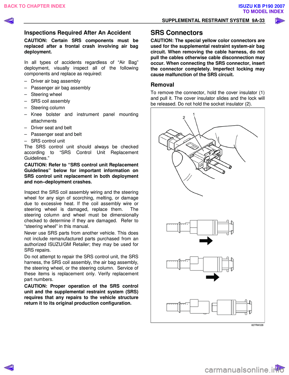
SRS Connectors
CAUTION: The special yellow color connectors are
used for the supplemental restraint system-air bag
circuit. When removing the cable harness, do not
pull the cables otherwise cable disconnection may
occur. When connecting the SRS connector, insert
the connector completely. Imperfect locking may
cause malfunction of the SRS circuit.
Removal
To remove the connector, hold the cover insulator (1)
and pull it. The cover insulator slides and the lock will
be released. Do not hold the socket insulator (2).
827RW 028
BACK TO CHAPTER INDEX TO MODEL INDEXISUZU KB P190 2007