2007 ISUZU KB P190 sensor
[x] Cancel search: sensorPage 1848 of 6020
ENGINE CONTROL SYSTEM (4JK1/4JJ1) 6E-231
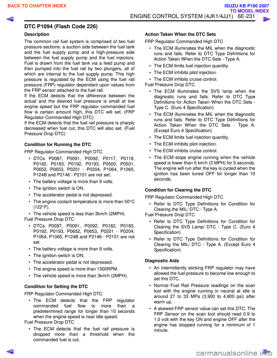
DTC P1094 (Flash Code 226)
Description
The common rail fuel system is comprised of two fuel
pressure sections: a suction side between the fuel tank
and the fuel supply pump and a high-pressure side
between the fuel supply pump and the fuel injectors.
Fuel is drawn from the fuel tank via a feed pump and
then pumped into the fuel rail by two plungers, all of
which are internal to the fuel supply pump. This high
pressure is regulated by the ECM using the fuel rail
pressure (FRP) regulator dependant upon values from
the FRP sensor attached to the fuel rail.
If the ECM detects that the difference between the
actual and the desired fuel pressure is small at low
engine speed but the FRP regulator commanded fuel
flow is certain amount high, this DTC will set. (FRP
Regulator Commanded High DTC)
If the ECM detects that the fuel rail pressure is sharply
decreased when fuel cut, this DTC will also set. (Fuel
Pressure Drop DTC)
Condition for Running the DTC
FRP Regulator Commanded High DTC • DTCs P0087, P0091, P0092, P0117, P0118, P0182, P0183, P0192, P0193, P0500, P0501,
P0652, P0653, P0201 - P0204, P1064, P1065,
P124B and P2146 - P2151 are not set.
• The battery voltage is more than 9 volts.
• The ignition switch is ON.
• The accelerator pedal is not depressed.
• The engine coolant temperature is more than 50 °C
(122 °F).
• The vehicle speed is less than 3km/h (2MPH).
Fuel Pressure Drop DTC
• DTCs P0087, P0091, P0092, P0182, P0183, P0192, P0193, P0652, P0653, P0201 - P0204,
P1064, P1065, P124B and P2146 - P2151 are not
set.
• The battery voltage is more than 9 volts.
• The ignition switch is ON.
• The accelerator pedal is not depressed.
• The engine speed is more than 1500RPM.
• The vehicle speed is more than 3km/h (2MPH).
Condition for Setting the DTC
FRP Regulator Commanded High DTC • The ECM detects that the FRP regulator commanded fuel flow is more than a
predetermined range for longer than 10 seconds
when the engine speed is near idle speed.
Fuel Pressure Drop DTC
• The ECM detects that the fuel rail pressure is dropped more than a threshold when the
commanded fuel is cut. Action Taken When the DTC Sets
FRP Regulator Commanded High DTC • The ECM illuminates the MIL when the diagnostic runs and fails. Refer to DTC Type Definitions for
Action Taken When the DTC Sets - Type A.
• The ECM limits fuel injection quantity.
• The ECM inhibits pilot injection.
• The ECM inhibits cruise control.
Fuel Pressure Drop DTC
• The ECM illuminates the SVS lamp when the diagnostic runs and fails. Refer to DTC Type
Definitions for Action Taken When the DTC Sets -
Type C. (Euro 4 Specification)
• The ECM illuminates the MIL when the diagnostic runs and fails. Refer to DTC Type Definitions for
Action Taken When the DTC Sets - Type A.
(Except Euro 4 Specification)
• The ECM limits fuel injection quantity.
• The ECM inhibits pilot injection.
• The ECM inhibits cruise control.
• The ECM stops engine running when the vehicle speed is lower than 5 km/h (3 MPH) for 5 seconds.
The engine will run after the key is cycled when the
ignition has been tuned OFF for longer than 10
seconds.
Condition for Clearing the DTC
FRP Regulator Commanded High DTC • Refer to DTC Type Definitions for Condition for Clearing the MIL/ DTC - Type A.
Fuel Pressure Drop DTC
• Refer to DTC Type Definitions for Condition for Clearing the SVS Lamp/ DTC - Type C. (Euro 4
Specification)
• Refer to DTC Type Definitions for Condition for Clearing the MIL/ DTC - Type A. (Except Euro 4
Specification)
Diagnostic Aids • An intermittently sticking FRP regulator may have allowed the fuel pressure to become low enough to
set this DTC.
• Normal Fuel Rail Pressure readings on the scan tool with the engine running in neutral at idle is
around 27 to 33 MPa (3,900 to 4,800 psi) after
warm up.
• A skewed FRP sensor value can set this DTC. The FRP Sensor on the scan tool should read 0.9 to
1.0 volt with the key ON and engine OFF after the
engine has stopped running for a minimum of 1
minute.
BACK TO CHAPTER INDEX
TO MODEL INDEX
ISUZU KB P190 2007
Page 1849 of 6020
6E-232 ENGINE CONTROL SYSTEM (4JK1/4JJ1)
Notice:• This DTC most likely indicates a loss of fuel pressure by a fuel leak from the high pressure
side. Inspect the high pressure side fuel leakage
between the fuel supply pump and fuel injector
first. • If the fuel tank is empty or near empty, air might be
allowed to go into the fuel system. With air in the
fuel system, smooth flow of fuel into the supply
pump is interrupted and this DTC may set. Perform
bleeding of fuel system after refilling.
Schematic Reference: Fuel System Routing Diagram
and Engine Controls Schematics
Connector End View Reference: Engine Controls
Connector End Views or ECM Connector End Views
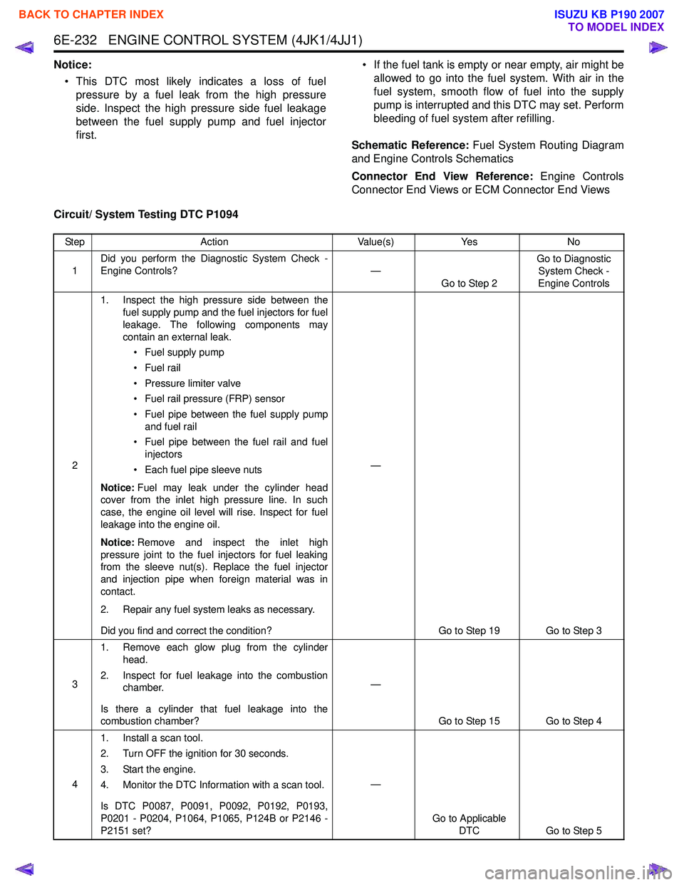
Circuit/ System Testing DTC P1094
Step Action Value(s)Yes No
1 Did you perform the Diagnostic System Check -
Engine Controls? —
Go to Step 2 Go to Diagnostic
System Check -
Engine Controls
2 1. Inspect the high pressure side between the
fuel supply pump and the fuel injectors for fuel
leakage. The following components may
contain an external leak.
• Fuel supply pump
• Fuel rail
• Pressure limiter valve
• Fuel rail pressure (FRP) sensor
• Fuel pipe between the fuel supply pump and fuel rail
• Fuel pipe between the fuel rail and fuel injectors
• Each fuel pipe sleeve nuts
Notice: Fuel may leak under the cylinder head
cover from the inlet high pressure line. In such
case, the engine oil level will rise. Inspect for fuel
leakage into the engine oil.
Notice: Remove and inspect the inlet high
pressure joint to the fuel injectors for fuel leaking
from the sleeve nut(s). Replace the fuel injector
and injection pipe when foreign material was in
contact.
2. Repair any fuel system leaks as necessary.
Did you find and correct the condition? —
Go to Step 19 Go to Step 3
3 1. Remove each glow plug from the cylinder
head.
2. Inspect for fuel leakage into the combustion chamber.
Is there a cylinder that fuel leakage into the
combustion chamber? —
Go to Step 15 Go to Step 4
4 1. Install a scan tool.
2. Turn OFF the ignition for 30 seconds.
3. Start the engine.
4. Monitor the DTC Information with a scan tool.
Is DTC P0087, P0091, P0092, P0192, P0193,
P0201 - P0204, P1064, P1065, P124B or P2146 -
P2151 set? —
Go to Applicable DTC Go to Step 5
BACK TO CHAPTER INDEX
TO MODEL INDEX
ISUZU KB P190 2007
Page 1850 of 6020

ENGINE CONTROL SYSTEM (4JK1/4JJ1) 6E-233
51. Turn OFF the ignition.
2. Wait 1 minute for the fuel pressure to bleed down from the fuel rail.
3. Turn ON the ignition, with the engine OFF. DO NOT start the engine.
4. Observe the Fuel Rail Pressure (FRP) Sensor parameter with the scan tool.
Does the scan tool indicate within the specified
value? 0.9 to 1.0 volt
Go to Step 6 Go to Step 13
6 1. Turn OFF the ignition.
2. Place the transmission in Neutral and set the parking brake.
3. Start the engine and let idle for at least 3 minutes while observing the DTC Information
with a scan tool.
Does the DTC fail this ignition? —
Go to Step 8 Go to Step 7
7 1. Accelerate the engine between idle and
W.O.T. (accelerator pedal full travel) many
times.
2. Let idle for at least 3 minutes while observing the DTC Information with a scan tool.
Does the DTC fail this ignition? —
Go to Step 18 Go to Step 8
8 1. Start the engine.
2. Perform the Cylinder Balance Test with a scan tool.
3. Command each injector OFF and verify an engine speed change for each injector.
Is there an injector that does not change engine
speed when commanded OFF? —
Go to Step 16 Go to Step 9
9 1. Check the fuel system line connections
between the fuel tank and the fuel supply
pump for tightness and all fuel hoses for cuts,
cracks and for the use of proper clamps.
Notice: Air in the fuel system will cause fuel rail
pressure fluctuations especially at high engine
speed and load, which may set this DTC.
2. Repair or replace as necessary.
Did you find and correct the condition? —
Go to Step 19 Go to Step 10
Step
Action Value(s)Yes No
BACK TO CHAPTER INDEX
TO MODEL INDEX
ISUZU KB P190 2007
Page 1852 of 6020
ENGINE CONTROL SYSTEM (4JK1/4JJ1) 6E-235
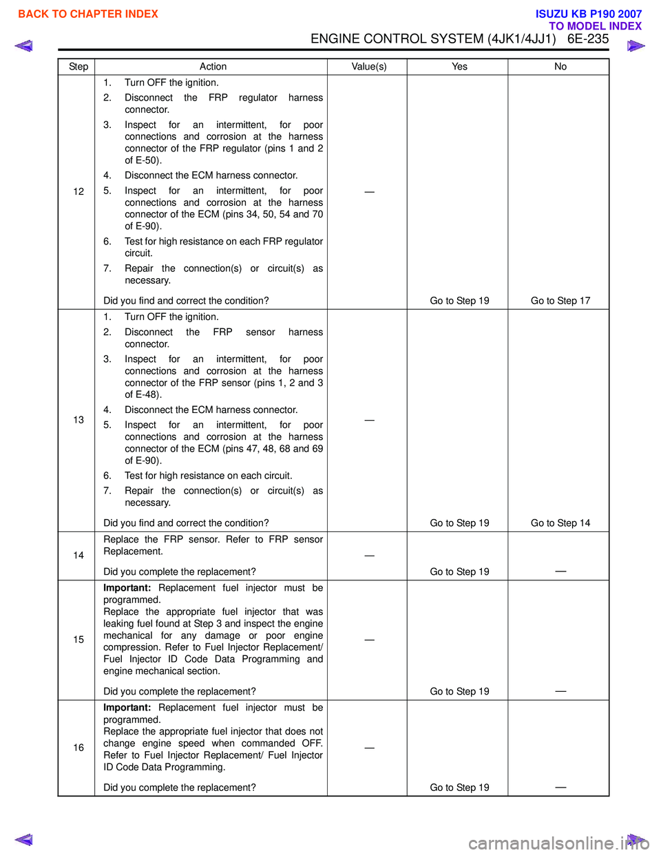
121. Turn OFF the ignition.
2. Disconnect the FRP regulator harness connector.
3. Inspect for an intermittent, for poor connections and corrosion at the harness
connector of the FRP regulator (pins 1 and 2
of E-50).
4. Disconnect the ECM harness connector.
5. Inspect for an intermittent, for poor connections and corrosion at the harness
connector of the ECM (pins 34, 50, 54 and 70
of E-90).
6. Test for high resistance on each FRP regulator circuit.
7. Repair the connection(s) or circuit(s) as necessary.
Did you find and correct the condition? —
Go to Step 19 Go to Step 17
13 1. Turn OFF the ignition.
2. Disconnect the FRP sensor harness connector.
3. Inspect for an intermittent, for poor connections and corrosion at the harness
connector of the FRP sensor (pins 1, 2 and 3
of E-48).
4. Disconnect the ECM harness connector.
5. Inspect for an intermittent, for poor connections and corrosion at the harness
connector of the ECM (pins 47, 48, 68 and 69
of E-90).
6. Test for high resistance on each circuit.
7. Repair the connection(s) or circuit(s) as necessary.
Did you find and correct the condition? —
Go to Step 19 Go to Step 14
14 Replace the FRP sensor. Refer to FRP sensor
Replacement.
Did you complete the replacement? —
Go to Step 19
—
15Important:
Replacement fuel injector must be
programmed.
Replace the appropriate fuel injector that was
leaking fuel found at Step 3 and inspect the engine
mechanical for any damage or poor engine
compression. Refer to Fuel Injector Replacement/
Fuel Injector ID Code Data Programming and
engine mechanical section.
Did you complete the replacement? —
Go to Step 19
—
16Important:
Replacement fuel injector must be
programmed.
Replace the appropriate fuel injector that does not
change engine speed when commanded OFF.
Refer to Fuel Injector Replacement/ Fuel Injector
ID Code Data Programming.
Did you complete the replacement? —
Go to Step 19
—
Step Action Value(s)Yes No
BACK TO CHAPTER INDEX
TO MODEL INDEX
ISUZU KB P190 2007
Page 1854 of 6020
ENGINE CONTROL SYSTEM (4JK1/4JJ1) 6E-237
DTC P1196, P1197 or P1198 (Flash Code 461)
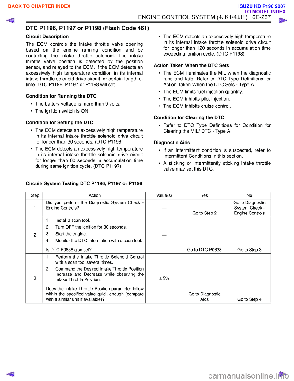
Circuit Description
The ECM controls the intake throttle valve opening
based on the engine running condition and by
controlling the intake throttle solenoid. The intake
throttle valve position is detected by the position
sensor, and relayed to the ECM. If the ECM detects an
excessively high temperature condition in its internal
intake throttle solenoid drive circuit for certain length of
time, DTC P1196, P1197 or P1198 will set.
Condition for Running the DTC • The battery voltage is more than 9 volts.
• The ignition switch is ON.
Condition for Setting the DTC • The ECM detects an excessively high temperature in its internal intake throttle solenoid drive circuit
for longer than 30 seconds. (DTC P1196)
• The ECM detects an excessively high temperature in its internal intake throttle solenoid drive circuit
for longer than 60 seconds in accumulation time
during same ignition cycle. (DTC P1197) • The ECM detects an excessively high temperature
in its internal intake throttle solenoid drive circuit
for longer than 120 seconds in accumulation time
exceeding ignition cycle. (DTC P1198)
Action Taken When the DTC Sets • The ECM illuminates the MIL when the diagnostic runs and fails. Refer to DTC Type Definitions for
Action Taken When the DTC Sets - Type A.
• The ECM limits fuel injection quantity.
• The ECM inhibits pilot injection.
• The ECM inhibits cruise control.
Condition for Clearing the DTC • Refer to DTC Type Definitions for Condition for Clearing the MIL/ DTC - Type A.
Diagnostic Aids • If an intermittent condition is suspected, refer to Intermittent Conditions in this section.
• A sticking or intermittently sticking intake throttle valve may set this DTC.
Circuit/ System Testing DTC P1196, P1197 or P1198
Step Action Value(s)Yes No
1 Did you perform the Diagnostic System Check -
Engine Controls? —
Go to Step 2 Go to Diagnostic
System Check -
Engine Controls
2 1. Install a scan tool.
2. Turn OFF the ignition for 30 seconds.
3. Start the engine.
4. Monitor the DTC Information with a scan tool.
Is DTC P0638 also set? —
Go to DTC P0638 Go to Step 3
3 1. Perform the Intake Throttle Solenoid Control
with a scan tool several times.
2. Command the Desired Intake Throttle Position Increase and Decrease while observing the
Intake Throttle Position.
Does the Intake Throttle Position parameter follow
within the specified value quick enough (compare
with a similar unit if available)? ±
5%
Go to Diagnostic Aids Go to Step 4
BACK TO CHAPTER INDEX
TO MODEL INDEX
ISUZU KB P190 2007
Page 1856 of 6020
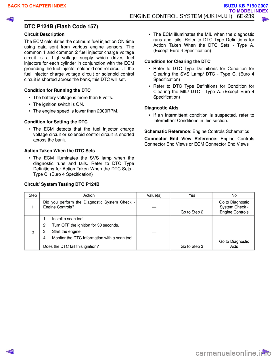
ENGINE CONTROL SYSTEM (4JK1/4JJ1) 6E-239
DTC P124B (Flash Code 157)
Circuit Description
The ECM calculates the optimum fuel injection ON time
using data sent from various engine sensors. The
common 1 and common 2 fuel injector charge voltage
circuit is a high-voltage supply which drives fuel
injectors for each cylinder in conjunction with the ECM
grounding the fuel injector solenoid control circuit. If the
fuel injector charge voltage circuit or solenoid control
circuit is shorted across the bank, this DTC will set.
Condition for Running the DTC • The battery voltage is more than 9 volts.
• The ignition switch is ON.
• The engine speed is lower than 2000RPM.
Condition for Setting the DTC • The ECM detects that the fuel injector charge voltage circuit or solenoid control circuit is shorted
across the bank.
Action Taken When the DTC Sets • The ECM illuminates the SVS lamp when the diagnostic runs and fails. Refer to DTC Type
Definitions for Action Taken When the DTC Sets -
Type C. (Euro 4 Specification) • The ECM illuminates the MIL when the diagnostic
runs and fails. Refer to DTC Type Definitions for
Action Taken When the DTC Sets - Type A.
(Except Euro 4 Specification)
Condition for Clearing the DTC • Refer to DTC Type Definitions for Condition for Clearing the SVS Lamp/ DTC - Type C. (Euro 4
Specification)
• Refer to DTC Type Definitions for Condition for Clearing the MIL/ DTC - Type A. (Except Euro 4
Specification)
Diagnostic Aids • If an intermittent condition is suspected, refer to Intermittent Conditions in this section.
Schematic Reference : Engine Controls Schematics
Connector End View Reference: Engine Controls
Connector End Views or ECM Connector End Views
Circuit/ System Testing DTC P124B
Step Action Value(s)Yes No
1 Did you perform the Diagnostic System Check -
Engine Controls? —
Go to Step 2 Go to Diagnostic
System Check -
Engine Controls
2 1. Install a scan tool.
2. Turn OFF the ignition for 30 seconds.
3. Start the engine.
4. Monitor the DTC Information with a scan tool.
Does the DTC fail this ignition? —
Go to Step 3 Go to Diagnostic
Aids
BACK TO CHAPTER INDEX
TO MODEL INDEX
ISUZU KB P190 2007
Page 1863 of 6020
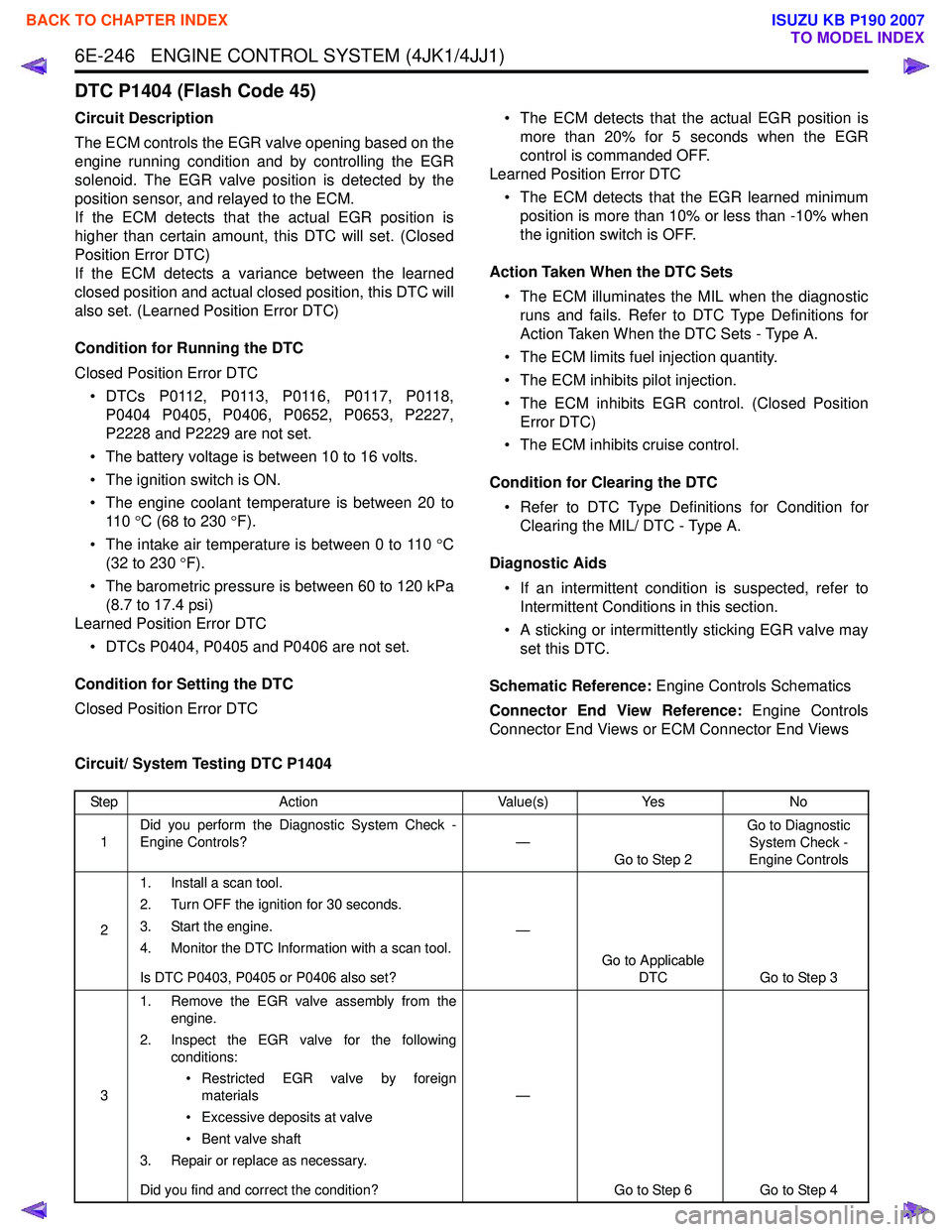
6E-246 ENGINE CONTROL SYSTEM (4JK1/4JJ1)
DTC P1404 (Flash Code 45)
Circuit Description
The ECM controls the EGR valve opening based on the
engine running condition and by controlling the EGR
solenoid. The EGR valve position is detected by the
position sensor, and relayed to the ECM.
If the ECM detects that the actual EGR position is
higher than certain amount, this DTC will set. (Closed
Position Error DTC)
If the ECM detects a variance between the learned
closed position and actual closed position, this DTC will
also set. (Learned Position Error DTC)
Condition for Running the DTC
Closed Position Error DTC • DTCs P0112, P0113, P0116, P0117, P0118, P0404 P0405, P0406, P0652, P0653, P2227,
P2228 and P2229 are not set.
• The battery voltage is between 10 to 16 volts.
• The ignition switch is ON.
• The engine coolant temperature is between 20 to 11 0 °C (68 to 230 °F).
• The intake air temperature is between 0 to 110 °C
(32 to 230 °F).
• The barometric pressure is between 60 to 120 kPa (8.7 to 17.4 psi)
Learned Position Error DTC
• DTCs P0404, P0405 and P0406 are not set.
Condition for Setting the DTC
Closed Position Error DTC • The ECM detects that the actual EGR position is
more than 20% for 5 seconds when the EGR
control is commanded OFF.
Learned Position Error DTC
• The ECM detects that the EGR learned minimum position is more than 10% or less than -10% when
the ignition switch is OFF.
Action Taken When the DTC Sets • The ECM illuminates the MIL when the diagnostic runs and fails. Refer to DTC Type Definitions for
Action Taken When the DTC Sets - Type A.
• The ECM limits fuel injection quantity.
• The ECM inhibits pilot injection.
• The ECM inhibits EGR control. (Closed Position Error DTC)
• The ECM inhibits cruise control.
Condition for Clearing the DTC • Refer to DTC Type Definitions for Condition for Clearing the MIL/ DTC - Type A.
Diagnostic Aids • If an intermittent condition is suspected, refer to Intermittent Conditions in this section.
• A sticking or intermittently sticking EGR valve may set this DTC.
Schematic Reference: Engine Controls Schematics
Connector End View Reference: Engine Controls
Connector End Views or ECM Connector End Views
Circuit/ System Testing DTC P1404
Step Action Value(s)Yes No
1 Did you perform the Diagnostic System Check -
Engine Controls? —
Go to Step 2 Go to Diagnostic
System Check -
Engine Controls
2 1. Install a scan tool.
2. Turn OFF the ignition for 30 seconds.
3. Start the engine.
4. Monitor the DTC Information with a scan tool.
Is DTC P0403, P0405 or P0406 also set? —
Go to Applicable DTC Go to Step 3
3 1. Remove the EGR valve assembly from the
engine.
2. Inspect the EGR valve for the following conditions:
• Restricted EGR valve by foreign materials
• Excessive deposits at valve
• Bent valve shaft
3. Repair or replace as necessary.
Did you find and correct the condition? —
Go to Step 6 Go to Step 4
BACK TO CHAPTER INDEX
TO MODEL INDEX
ISUZU KB P190 2007
Page 1865 of 6020
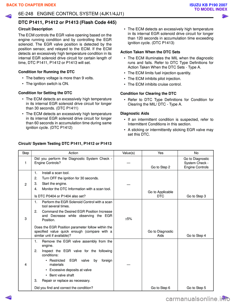
6E-248 ENGINE CONTROL SYSTEM (4JK1/4JJ1)
DTC P1411, P1412 or P1413 (Flash Code 445)
Circuit Description
The ECM controls the EGR valve opening based on the
engine running condition and by controlling the EGR
solenoid. The EGR valve position is detected by the
position sensor, and relayed to the ECM. If the ECM
detects an excessively high temperature condition in its
internal EGR solenoid drive circuit for certain length of
time, DTC P1411, P1412 or P1413 will set.
Condition for Running the DTC • The battery voltage is more than 9 volts.
• The ignition switch is ON.
Condition for Setting the DTC • The ECM detects an excessively high temperature in its internal EGR solenoid drive circuit for longer
than 30 seconds. (DTC P1411)
• The ECM detects an excessively high temperature in its internal EGR solenoid drive circuit for longer
than 60 seconds in accumulation time during same
ignition cycle. (DTC P1412) • The ECM detects an excessively high temperature
in its internal EGR solenoid drive circuit for longer
than 120 seconds in accumulation time exceeding
ignition cycle. (DTC P1413)
Action Taken When the DTC Sets • The ECM illuminates the MIL when the diagnostic runs and fails. Refer to DTC Type Definitions for
Action Taken When the DTC Sets - Type A.
• The ECM limits fuel injection quantity.
• The ECM inhibits pilot injection.
• The ECM inhibits cruise control.
Condition for Clearing the DTC • Refer to DTC Type Definitions for Condition for Clearing the MIL/ DTC - Type A.
Diagnostic Aids • If an intermittent condition is suspected, refer to Intermittent Conditions in this section.
• A sticking or intermittently sticking EGR valve may set this DTC.
Circuit/ System Testing DTC P1411, P1412 or P1413
Step Action Value(s)Yes No
1 Did you perform the Diagnostic System Check -
Engine Controls? —
Go to Step 2 Go to Diagnostic
System Check -
Engine Controls
2 1. Install a scan tool.
2. Turn OFF the ignition for 30 seconds.
3. Start the engine.
4. Monitor the DTC Information with a scan tool.
Is DTC P0404 or P1404 also set? —
Go to Applicable DTC Go to Step 3
3 1. Perform the EGR Solenoid Control with a scan
tool several times.
2. Command the Desired EGR Position Increase and Decrease while observing the EGR
Position.
Does the EGR Position parameter follow within the
specified value quick enough (compare with a
similar unit if available)? ±
5%
Go to Diagnostic Aids Go to Step 4
4 1. Remove the EGR valve assembly from the
engine.
2. Inspect the EGR valve for the following conditions:
• Restricted EGR valve by foreign materials
• Excessive deposits at valve
• Bent valve shaft
3. Repair or replace as necessary.
Did you find and correct the condition? —
Go to Step 6 Go to Step 5
BACK TO CHAPTER INDEX
TO MODEL INDEX
ISUZU KB P190 2007