Page 3273 of 6020

Engine Management – V6 – General Information Page 6C1-1–31
4.15 Ignition Coil and Spark Plug
Long-life platinum tip spark plugs are used which, along with
the ignition coil spark plug boot and spring, require
replacement at 100,000 kilometre service intervals. The
spark plugs, featuring a J-gap and a conical seat, do not
require inspection between services, and must not be re-
gapped.
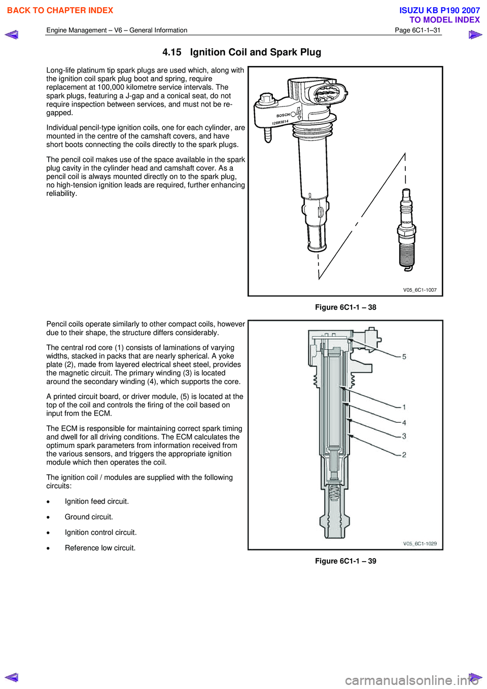
Individual pencil-type ignition coils, one for each cylinder, are
mounted in the centre of the camshaft covers, and have
short boots connecting the coils directly to the spark plugs.
The pencil coil makes use of the space available in the spark
plug cavity in the cylinder head and camshaft cover. As a
pencil coil is always mounted directly on to the spark plug,
no high-tension ignition leads are required, further enhancing
reliability.
Figure 6C1-1 – 38
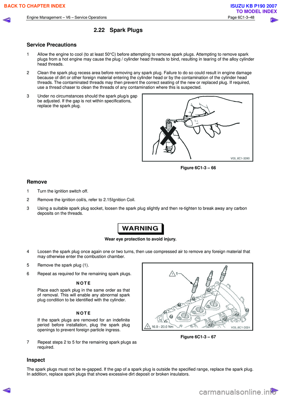
Pencil coils operate similarly to other compact coils, however
due to their shape, the structure differs considerably.
The central rod core (1) consists of laminations of varying
widths, stacked in packs that are nearly spherical. A yoke
plate (2), made from layered electrical sheet steel, provides
the magnetic circuit. The primary winding (3) is located
around the secondary winding (4), which supports the core.
A printed circuit board, or driver module, (5) is located at the
top of the coil and controls the firing of the coil based on
input from the ECM.
The ECM is responsible for maintaining correct spark timing
and dwell for all driving conditions. The ECM calculates the
optimum spark parameters from information received from
the various sensors, and triggers the appropriate ignition
module which then operates the coil.
The ignition coil / modules are supplied with the following
circuits:
• Ignition feed circuit.
• Ground circuit.
• Ignition control circuit.
• Reference low circuit.
Figure 6C1-1 – 39
BACK TO CHAPTER INDEX
TO MODEL INDEX
ISUZU KB P190 2007
Page 3572 of 6020

Engine Management – V6 – Service Operations Page 6C1-3–48
2.22 Spark Plugs
Service Precautions
1 Allow the engine to cool (to at least 50°C) before attempting to remove spark plugs. Attempting to remove spark
plugs from a hot engine may cause the plug / cylinder head threads to bind, resulting in tearing of the alloy cylinder
head threads.
2 Clean the spark plug recess area before removing any spark plug. Failure to do so could result in engine damage because of dirt or other foreign material entering the cylinder head or by the contamination of the cylinder head
threads. The contaminated threads may then prevent the correct seating of the new or replaced plug. If required,
use a thread chaser to clean the threads of any contamination where this is suspected.
3 Under no circumstances should the spark plug/s gap be adjusted. If the gap is not within specifications,
replace the spark plug.
Figure 6C1-3 – 66
Remove
1 Turn the ignition switch off.
2 Remove the ignition coil/s, refer to 2.15 Ignition Coil.
3 Using a suitable spark plug socket, loosen the spark plug slightly and then re-tighten to break away any carbon deposits on the threads.
Wear eye protection to avoid injury.
4 Loosen the spark plug once again one or two turns, then use compressed air to remove any foreign material that may otherwise enter the combustion chamber.
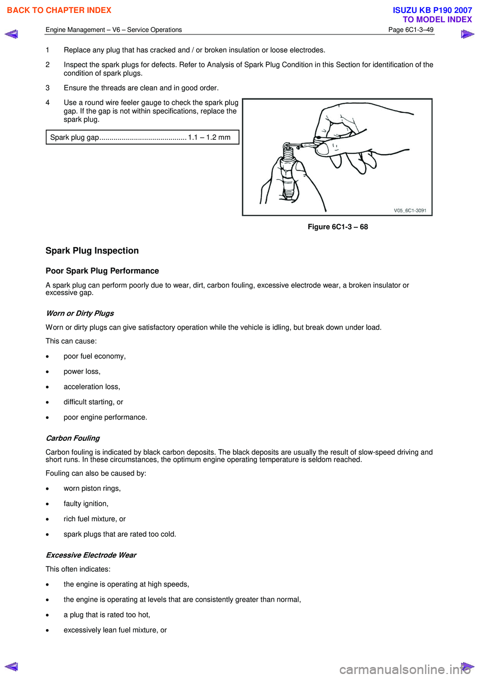
5 Remove the spark plug (1).
6 Repeat as required for the remaining spark plugs.
NOTE
Place each spark plug in the same order as that
of removal. This will enable any abnormal spark
plug condition to be identified with the cylinder.
NOTE
If the spark plugs are removed for an indefinite
period before installation, plug the spark plug
openings to prevent foreign particle ingress.
7 Repeat steps 2 to 5 for the remaining spark plugs as required.
Figure 6C1-3 – 67
Inspect
The spark plugs must not be re-gapped. If the gap of a spark plug is outside the specified range, replace the spark plug.
In addition, replace spark plugs that shows excessive dirt deposit or broken insulators.
BACK TO CHAPTER INDEX
TO MODEL INDEX
ISUZU KB P190 2007
Page 3573 of 6020

Engine Management – V6 – Service Operations Page 6C1-3–49
1 Replace any plug that has cracked and / or broken insulation or loose electrodes.
2 Inspect the spark plugs for defects. Refer to Analysis of Spark Plug Condition in this Section for identification of the condition of spark plugs.
3 Ensure the threads are clean and in good order.
4 Use a round wire feeler gauge to check the spark plug gap. If the gap is not within specifications, replace the
spark plug.
Spark plug gap ........................................... 1.1 – 1.2 mm
Figure 6C1-3 – 68
Spark Plug Inspection
Poor Spark Plug Performance
A spark plug can perform poorly due to wear, dirt, carbon fouling, excessive electrode wear, a broken insulator or
excessive gap.
Worn or Dirty Plugs
W orn or dirty plugs can give satisfactory operation while the vehicle is idling, but break down under load.
This can cause:
• poor fuel economy,
• power loss,
• acceleration loss,
• difficult starting, or
• poor engine performance.
Carbon Fouling
Carbon fouling is indicated by black carbon deposits. The black deposits are usually the result of slow-speed driving and
short runs. In these circumstances, the optimum engine operating temperature is seldom reached.
Fouling can also be caused by:
• worn piston rings,
• faulty ignition,
• rich fuel mixture, or
• spark plugs that are rated too cold.
Excessive Electrode Wear
This often indicates:
• the engine is operating at high speeds,
• the engine is operating at levels that are consistently greater than normal,
• a plug that is rated too hot,
• excessively lean fuel mixture, or
BACK TO CHAPTER INDEX
TO MODEL INDEX
ISUZU KB P190 2007