2007 ISUZU KB P190 spark plugs replace
[x] Cancel search: spark plugs replacePage 2516 of 6020
Engine Mechanical – V6 Page 6A1–37
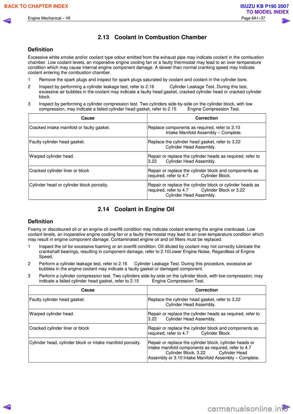
2.13 Coolant in Combustion Chamber
Definition
Excessive white smoke and/or coolant type odour emitted from the exhaust pipe may indicate coolant in the combustion
chamber. Low coolant levels, an inoperative engine cooling fan or a faulty thermostat may lead to an over-temperature
condition which may cause internal engine component damage. A slower than normal cranking speed may indicate
coolant entering the combustion chamber.
1 Remove the spark plugs and inspect for spark plugs saturated by coolant and coolant in the cylinder bore.
2 Inspect by performing a cylinder leakage test, refer to 2.16 Cylinder Leakage Test. During this test, excessive air bubbles in the coolant may indicate a faulty head gasket, cracked cylinder head or cracked cylinder
block.
3 Inspect by performing a cylinder compression test. Two cylinders side-by-side on the cylinder block, with low compression, may indicate a failed cylinder head gasket, refer to 2.15 Engine Compression Test.
Cause Correction
Cracked intake manifold or faulty gasket. Replace components as required, refer to 3.10
Intake Manifold Assembly – Complete.
Faulty cylinder head gasket. Replace the cylinder head gasket, refer to 3.22
Cylinder Head Assembly.
W arped cylinder head. Repair or replace the cylinder heads as required, refer to
3.22 Cylinder Head Assembly.
Cracked cylinder liner or block Repair or replace the cylinder block and components as
required, refer to 4.7 Cylinder Block.
Cylinder head or cylinder block porosity. Repair or replace the cylinder block or cylinder heads as
required, refer to 4.7 Cylinder Block or 3.22
Cylinder Head Assembly.
2.14 Coolant in Engine Oil
Definition
Foamy or discoloured oil or an engine oil overfill condition may indicate coolant entering the engine crankcase. Low
coolant levels, an inoperative engine cooling fan or a faulty thermostat may lead to an over-temperature condition which
may result in engine component damage. Contaminated engine oil and oil filters must be replaced.
1 Inspect the oil for excessive foaming or an overfill condition. Oil diluted by coolant may not correctly lubricate the crankshaft bearings, resulting in component damage, refer to 2.10 Lower Engine Noise, Regardless of Engine
Speed.
2 Perform a cylinder leakage test, refer to 2.16 Cylinder Leakage Test. During this procedure, excessive air bubbles in the engine coolant may indicate a faulty gasket or damaged component.
3 Perform a cylinder compression test. Two cylinders side-by-side on the cylinder block, with low compression, may indicate a failed cylinder head gasket, refer to 2.15 Engine Compression Test.
Cause Correction
Faulty cylinder head gasket. Replace the cylinder head gasket, refer to 3.22
Cylinder Head Assembly.
W arped cylinder head. Repair or replace the cylinder heads as required, refer to
3.22 Cylinder Head Assembly.
Cracked cylinder liner or block Repair or replace the cylinder block and components as
required, refer to 4.7 Cylinder Block.
Cylinder head, cylinder block or intake manifold porosity. Repair or replace the cylinder block, cylinder heads or intake manifold components as required, refer to 4.7
Cylinder Block, 3.22 Cylinder Head
Assembly or 3.10 Intake Manifold Assembly – Complete.
BACK TO CHAPTER INDEX
TO MODEL INDEX
ISUZU KB P190 2007
Page 2518 of 6020

Engine Mechanical – V6 Page 6A1–39
2.16 Cylinder Leakage Test
A leakage test may be performed to measure cylinder/combustion chamber leakage. High cylinder leakage may indicate
one or more of the following:
• worn or burnt valves,
• broken valve springs,
• stuck valve lifters,
• incorrect valve lash/adjustment,
• damaged piston,
• worn piston rings,
• worn or scored cylinder bore,
• damaged cylinder head gasket,
• cracked or damaged cylinder head, or
• cracked or damaged engine block.
1 Disconnect the battery ground negative cable.
2 Remove the spark plugs from all cylinders, refer to 6C1-3 Engine Management – V6 – Service Operations.
3 Rotate the crankshaft to place the piston in the cylinder being tested at top dead centre (TDC) of the compression stroke.
4 Install a commercially available cylinder head leak down tester into the spark plug hole.
NOTE
If required, hold the crankshaft balancer bolt to
prevent the engine from rotating.
5 Apply shop air pressure to the cylinder head leak down tester and adjust according to the manufacturers instructions.
6 Record the cylinder leakage value. Cylinder leakage that exceeds 25 percent is considered excessive and may require component service. In excessive leakage situations, inspect for the following conditions:
• air leakage sounds at the throttle body or air inlet duct that may indicate a worn or burnt intake valve or a
broken valve spring,
• air leakage sounds at the exhaust system tailpipe that may indicate a worn or burnt exhaust valve or a broken
valve spring,
• air leakage sounds from the crankcase, oil level indicator tube, or oil fill tube that may indicate worn piston
rings, a damaged piston, a worn or scored cylinder bore, a damaged engine block or a damaged cylinder
head, or
• air bubbles in the cooling system may indicate a damaged cylinder head or a damaged cylinder head gasket.
7 Perform the leakage test on the remaining cylinders and record the values.
2.17 Engine Oil Consumption Diagnosis
Definition
Excessive oil consumption (not due to leaks) is the use of 3 litres or more of engine oil within 10,000 kilometres. Prior to
performing oil pressure testing, a preliminary inspection of the vehicle should be performed. During the preliminary visual
inspection, the following likely causes of excessive oil usage should be investigated.
Cause Correction
External oil leaks. Refer to 2.18 Engine Oil Leak Diagnosis.
Incorrect oil level or reading of the oil level indicator. Check for the correct oil level, refer to 3.1 Engine Oil.
Incorrect oil viscosity. Replace the engine oil, using the recommended SAE grade
of engine oil, refer to 3.1 Engine Oil.
Continuous high-speed driving or severe usage. Service vehicle more frequently, refer to 0B Lubrication and
Service.
Crankcase ventilation system restricted or malfunctioning. Repair or replace crankcase ventilation system components as required, refer to 6C1-3 Engine Management – V6 –
Service Operations.
BACK TO CHAPTER INDEX
TO MODEL INDEX
ISUZU KB P190 2007
Page 2810 of 6020
Engine Mechanical – V6 Page 6A1–33
Page 6A1–33
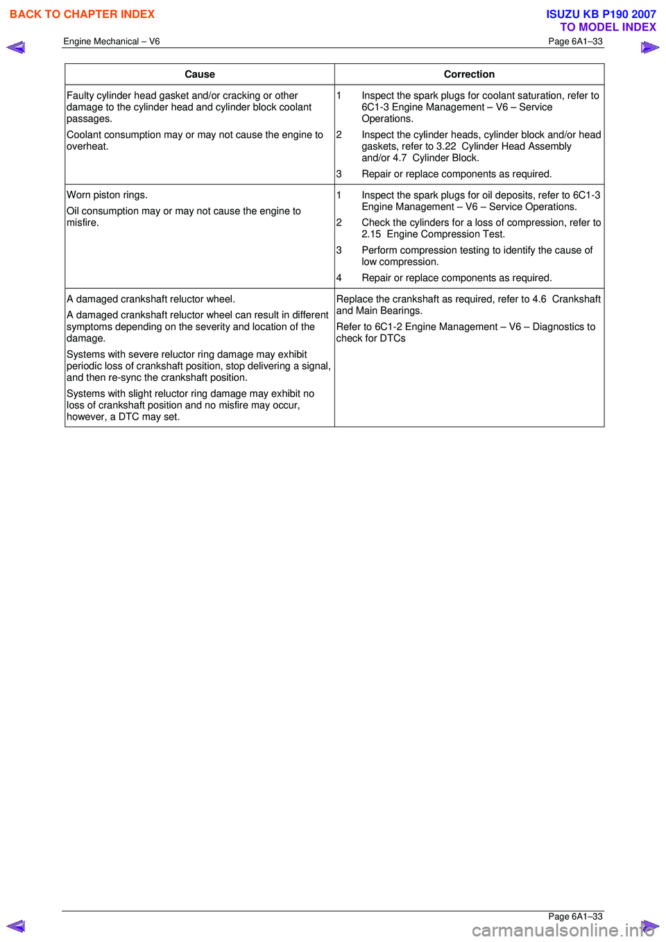
Cause Correction
Faulty cylinder head gasket and/or cracking or other
damage to the cylinder head and cylinder block coolant
passages.
Coolant consumption may or may not cause the engine to
overheat. 1 Inspect the spark plugs for
coolant saturation, refer to
6C1-3 Engine Management – V6 – Service
Operations.
2 Inspect the cylinder heads, cylinder block and/or head gaskets, refer to 3.22 Cylinder Head Assembly
and/or 4.7 Cylinder Block.
3 Repair or replace components as required.
Worn piston rings.
Oil consumption may or ma y not cause the engine to
misfire. 1 Inspect the spark plugs for oil deposits, refer to 6C1-3
Engine Management – V6 – Service Operations.
2 Check the cylinders for a loss of compression, refer to 2.15 Engine Compression Test.
3 Perform compression testing to identify the cause of
low compression.
4 Repair or replace components as required.
A damaged crankshaft reluctor wheel.
A damaged crankshaft reluctor wheel can result in different
symptoms depending on the severity and location of the
damage.
Systems with severe relu ctor ring damage may exhibit
periodic loss of crankshaft posit ion, stop delivering a signal,
and then re-sync the crankshaft position.
Systems with slight reluctor ring damage may exhibit no
loss of crankshaft position and no misfire may occur,
however, a DTC may set. Replace the crankshaft as required, refer to 4.6 Crankshaft
and Main Bearings.
Refer to 6C1-2 Engine Management – V6 – Diagnostics to
check for DTCs
BACK TO CHAPTER INDEX
TO MODEL INDEX
ISUZU KB P190 2007
Page 2811 of 6020
Engine Mechanical – V6 Page 6A1–34
Page 6A1–34
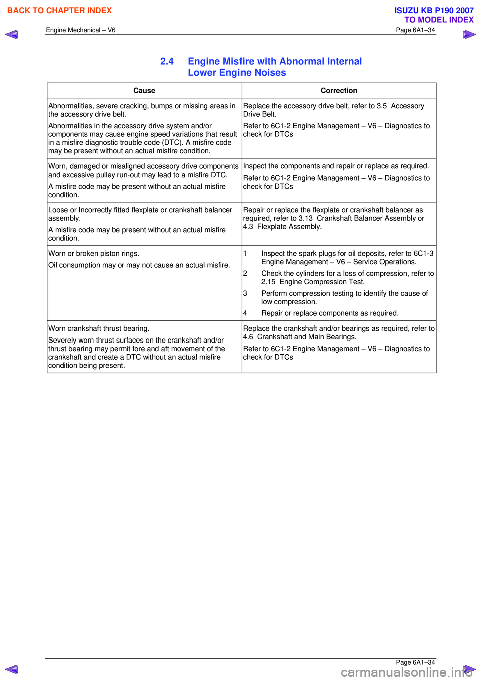
2.4 Engine Misfire with Abnormal Internal
Lower Engine Noises
Cause Correction
Abnormalities, severe cracking, bumps or missing areas in
the accessory drive belt.
Abnormalities in the accessory drive system and/or
components may cause engine speed variations that result
in a misfire diagnostic trouble code (DTC). A misfire code
may be present without an ac tual misfire condition. Replace the accessory drive belt, refer to 3.5 Accessory
Drive Belt.
Refer to 6C1-2 Engine Management – V6 – Diagnostics to
check for DTCs
Worn, damaged or misaligned accessory drive components
and excessive pulley run-out may lead to a misfire DTC.
A misfire code may be present without an actual misfire
condition. Inspect the components and repair or replace as required.
Refer to 6C1-2 Engine Management – V6 – Diagnostics to
check for DTCs
Loose or Incorrectly fitted flexplate or crankshaft balancer
assembly.
A misfire code may be present without an actual misfire
condition. Repair or replace the flexplat
e or crankshaft balancer as
required, refer to 3.13 Crankshaft Balancer Assembly or
4.3 Flexplate Assembly.
Worn or broken piston rings.
Oil consumption may or may not cause an actual misfire. 1 Inspect the spark plugs for oil deposits, refer to 6C1-3
Engine Management – V6 – Service Operations.
2 Check the cylinders for a loss of compression, refer to 2.15 Engine Compression Test.
3 Perform compression testing to identify the cause of
low compression.
4 Repair or replace components as required.
Worn crankshaft thrust bearing.
Severely worn thrust surfaces on the crankshaft and/or
thrust bearing may permit fore and aft movement of the
crankshaft and create a DTC wi thout an actual misfire
condition being present. Replace the crankshaft and/or bear
ings as required, refer to
4.6 Crankshaft and Main Bearings.
Refer to 6C1-2 Engine Management – V6 – Diagnostics to
check for DTCs
BACK TO CHAPTER INDEX
TO MODEL INDEX
ISUZU KB P190 2007
Page 2813 of 6020
Engine Mechanical – V6 Page 6A1–36
Page 6A1–36
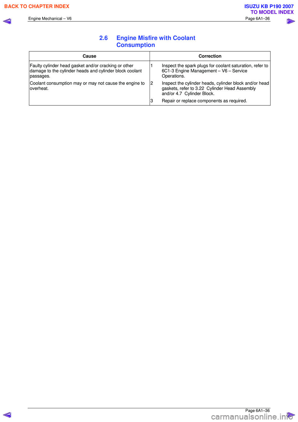
2.6 Engine Misfire with Coolant
Consumption
Cause Correction
Faulty cylinder head gasket and/or cracking or other
damage to the cylinder heads and cylinder block coolant
passages.
Coolant consumption may or may not cause the engine to
overheat. 1 Inspect the spark plugs for
coolant saturation, refer to
6C1-3 Engine Management – V6 – Service
Operations.
2 Inspect the cylinder heads, cylinder block and/or head gaskets, refer to 3.22 Cylinder Head Assembly
and/or 4.7 Cylinder Block.
3 Repair or replace components as required.
BACK TO CHAPTER INDEX
TO MODEL INDEX
ISUZU KB P190 2007
Page 2814 of 6020
Engine Mechanical – V6 Page 6A1–37
Page 6A1–37
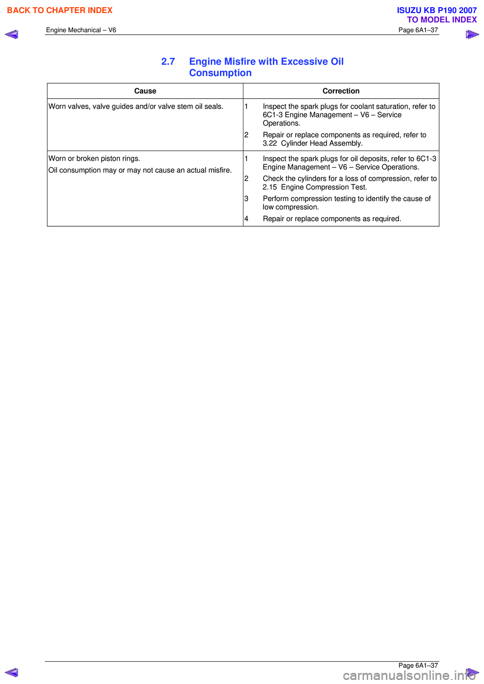
2.7 Engine Misfire with Excessive Oil
Consumption
Cause Correction
Worn valves, valve guides and/or valve stem oil seals. 1 Inspect the spark plugs for coolant saturation, refer to
6C1-3 Engine Management – V6 – Service
Operations.
2 Repair or replace components as required, refer to 3.22 Cylinder Head Assembly.
Worn or broken piston rings.
Oil consumption may or may not cause an actual misfire. 1 Inspect the spark plugs for oil deposits, refer to 6C1-3
Engine Management – V6 – Service Operations.
2 Check the cylinders for a loss of compression, refer to 2.15 Engine Compression Test.
3 Perform compression testing to identify the cause of
low compression.
4 Repair or replace components as required.
BACK TO CHAPTER INDEX
TO MODEL INDEX
ISUZU KB P190 2007
Page 2819 of 6020
Engine Mechanical – V6 Page 6A1–42
Page 6A1–42
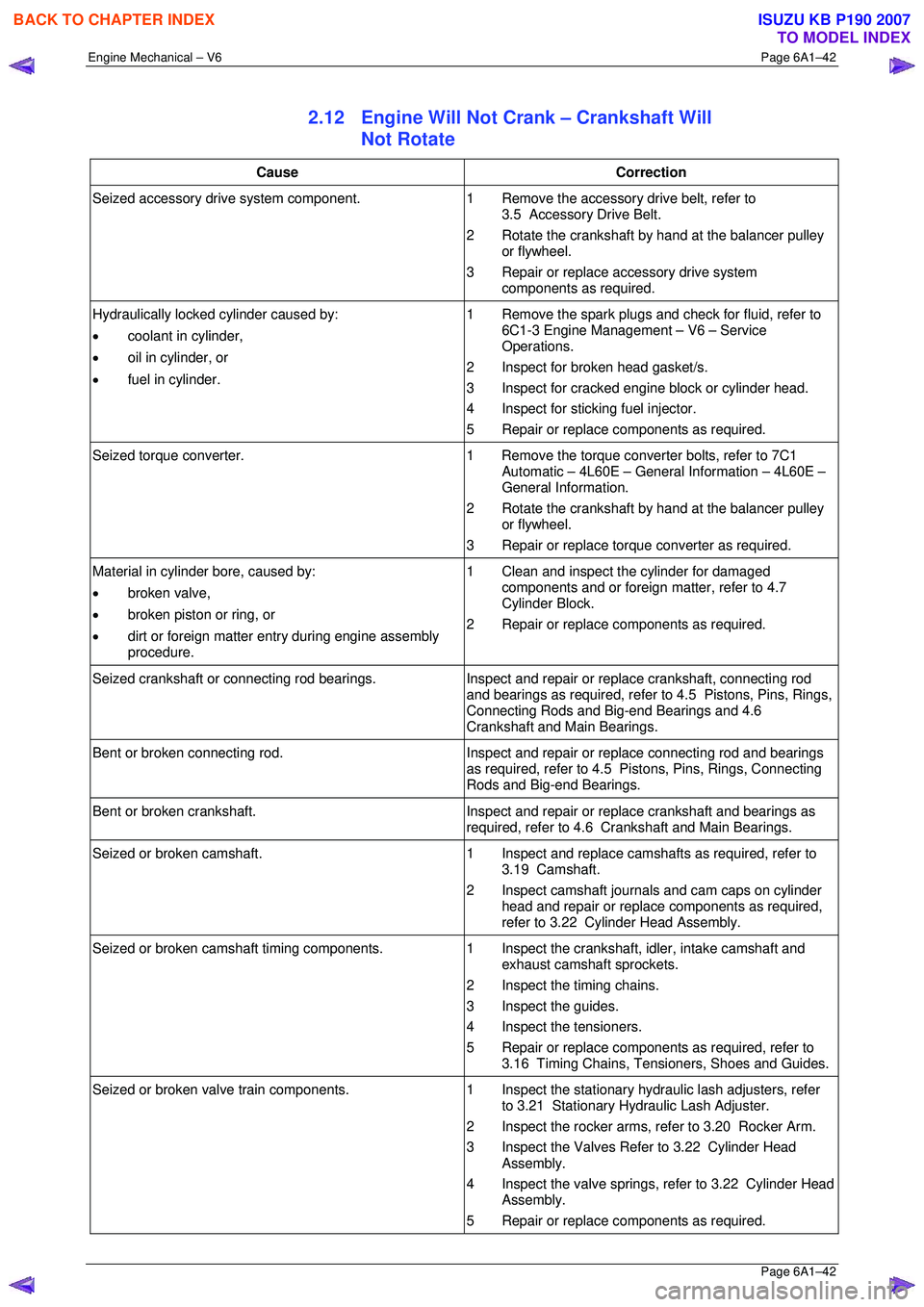
2.12 Engine Will Not Crank – Crankshaft Will
Not Rotate
Cause Correction
Seized accessory drive system component. 1 Remove the accessory drive belt, refer to
3.5 Accessory Drive Belt.
2 Rotate the crankshaft by hand at the balancer pulley or flywheel.
3 Repair or replace accessory drive system components as required.
Hydraulically locked cylinder caused by:
• coolant in cylinder,
• oil in cylinder, or
• fuel in cylinder. 1 Remove the spark plugs and check for fluid, refer to
6C1-3 Engine Management – V6 – Service
Operations.
2 Inspect for broken head gasket/s.
3 Inspect for cracked engine block or cylinder head.
4 Inspect for sticking fuel injector.
5 Repair or replace components as required.
Seized torque converter. 1 Remove the torque converter bolts, refer to 7C1
Automatic – 4L60E – General Information – 4L60E –
General Information.
2 Rotate the crankshaft by hand at the balancer pulley or flywheel.
3 Repair or replace torque converter as required.
Material in cylinder bore, caused by:
• broken valve,
• broken piston or ring, or
• dirt or foreign matter entry during engine assembly
procedure. 1 Clean and inspect the cylinder for damaged
components and or foreign matter, refer to 4.7
Cylinder Block.
2 Repair or replace components as required.
Seized crankshaft or connecting rod bearings. Inspect and repair or replace crankshaft, connecting rod
and bearings as required, refer to 4.5 Pistons, Pins, Rings,
Connecting Rods and Big-end Bearings and 4.6
Crankshaft and Main Bearings.
Bent or broken connecting rod. Inspect and repair or replace connecting rod and bearings
as required, refer to 4.5 Pistons, Pins, Rings, Connecting
Rods and Big-end Bearings.
Bent or broken crankshaft. Inspect and repair or replace crankshaft and bearings as
required, refer to 4.6 Crankshaft and Main Bearings.
Seized or broken camshaft. 1 Inspect and replace camshafts as required, refer to
3.19 Camshaft.
2 Inspect camshaft journals and cam caps on cylinder head and repair or replace components as required,
refer to 3.22 Cylinder Head Assembly.
Seized or broken camshaft timing components. 1 Inspect the crankshaft, idler, intake camshaft and
exhaust camshaft sprockets.
2 Inspect the timing chains.
3 Inspect the guides.
4 Inspect the tensioners.
5 Repair or replace components as required, refer to 3.16 Timing Chains, Tensioners, Shoes and Guides.
Seized or broken valve train components. 1 Inspect the stationary hydraulic lash adjusters, refer
to 3.21 Stationary Hydraulic Lash Adjuster.
2 Inspect the rocker arms, re fer to 3.20 Rocker Arm.
3 Inspect the Valves Refer to 3.22 Cylinder Head Assembly.
4 Inspect the valve springs, refer to 3.22 Cylinder Head Assembly.
5 Repair or replace components as required.
BACK TO CHAPTER INDEX
TO MODEL INDEX
ISUZU KB P190 2007
Page 2820 of 6020
Engine Mechanical – V6 Page 6A1–43
Page 6A1–43
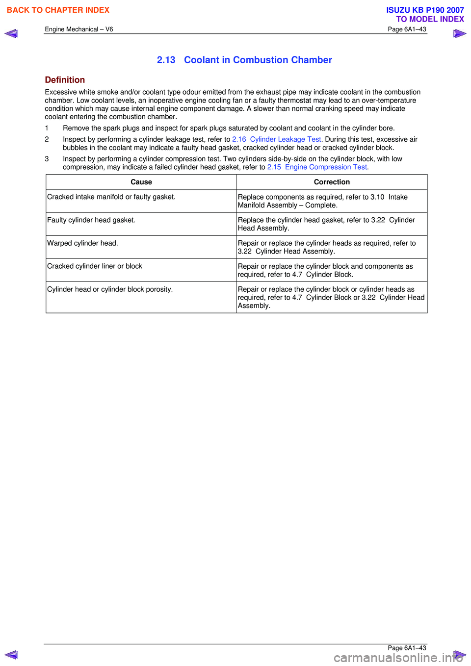
2.13 Coolant in Combustion Chamber
Definition
Excessive white smoke and/or coolant type odour emitted from the exhaust pipe may indicate coolant in the combustion
chamber. Low coolant levels, an inoperativ e engine cooling fan or a faulty thermostat may lead to an over-temperature
condition which may cause internal engine component damage. A slower than normal cranking speed may indicate
coolant entering the combustion chamber.
1 Remove the spark plugs and inspect for spark plugs sa turated by coolant and coolant in the cylinder bore.
2 Inspect by performing a cylinder leakage test, refer to 2.16 Cylinder Leakage Test. During this test, excessive air
bubbles in the coolant may indicate a faulty head ga sket, cracked cylinder head or cracked cylinder block.
3 Inspect by performing a cylinder compression test. Two cylinders side-by-side on the cylinder block, with low
compression, may indicate a fa iled cylinder head gasket, refer to 2.15 Engine Compression Test.
Cause Correction
Cracked intake manifold or faulty gasket. Replace components as required, refer to 3.10 Intake
Manifold Assembly – Complete.
Faulty cylinder head gasket. Replace the cylinder head gasket, refer to 3.22 Cylinder
Head Assembly.
Warped cylinder head. Repair or replace the cylinder heads as required, refer to
3.22 Cylinder Head Assembly.
Cracked cylinder liner or block Repair or replace the cylinder block and components as
required, refer to 4.7 Cylinder Block.
Cylinder head or cylinder block porosity. Repair or replace the cylinder block or cylinder heads as
required, refer to 4.7 Cylinder Block or 3.22 Cylinder Head
Assembly.
BACK TO CHAPTER INDEX
TO MODEL INDEX
ISUZU KB P190 2007