2007 ISUZU KB P190 spark plugs replace
[x] Cancel search: spark plugs replacePage 2224 of 6020
6E–54 ENGINE DRIVEABILITY AND EMISSIONS
GENERAL DESCRIPTION FOR ELECTRIC
IGNITION SYSTEM
The engine use two ignition coils, one per two cylinders.
A two wire connector provides a battery voltage primary
supply through the ignition fuse.
The ignition control spark timing is the ECM’s method of
controlling the spark advance and the ignition dwell.
The ignition control spark advance and the ignition dwell
are calculated by the ECM using the following inputs.
• Engine speed
• Crankshaft position (CKP) sensor
• Engine coolant temperature (ECT) sensor
• Throttle position sensor
• Vehicle speed sensor
• ECM and ignition system supply voltage
Ignition coil works to generate only the secondary
voltage be receiving the primary voltage from ECM.
The primary voltage is generated at the coil driver
located in the ECM. The coil driver generate the primary
voltage based on the crankshaft position signal. In
accordance with the crankshaft position signal, ignition
coil driver determines the adequate ignition timing and
also cylinder number to ignite.
Ignition timing is determined the coolant temperature,
intake air temperature, engine speed, engine load,
knock sensor signal, etc.
Spark Plug
Although worn or dirty spark plugs may give satisfactory
operation at idling speed, they frequently fail at higher
engine speeds. Faulty spark plugs may cause poor fuel
economy, power loss, loss of speed, hard starting and
generally poor engine performance. Follow the
scheduled maintenance service recommendations to
ensure satisfactory spark plug performance. Refer to
Maintenance and Lubrication .
Normal spark plug operation will result in brown to
grayish-tan deposits appearing on the insulator portion
of the spark plug. A small amount of red-brown, yellow,
and white powdery material may also be present on the
insulator tip around the center electrode. These
deposits are normal combustion by-products of fuels
and lubricating oils with additives. Some electrode wear
will also occur. Engines which are not running properly
are often referred to as “misfiring.” This means the
ignition spark is not igniting the air/fuel mixture at the
proper time. While other ignition and fuel system causes
must also be considered, possible causes include
ignition system conditions which allow the spark voltage
to reach ground in some other manner than by jumping
across the air gap at the tip of the spark plug, leaving
the air/fuel mixture unburned. Misfiring may also occur
when the tip of the spark plug becomes overheated and
ignites the mixture before the spark jumps. This is
referred to as “pre-ignition.”
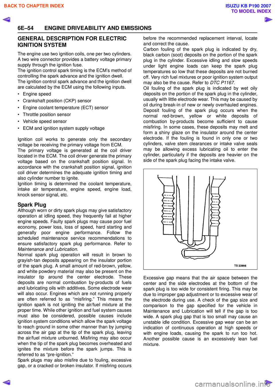
Spark plugs may also misfire due to fouling, excessive
gap, or a cracked or broken insulator. If misfiring occurs before the recommended replacement interval, locate
and correct the cause.
Carbon fouling of the spark plug is indicated by dry,
black carbon (soot) deposits on the portion of the spark
plug in the cylinder. Excessive idling and slow speeds
under light engine loads can keep the spark plug
temperatures so low that these deposits are not burned
off. Very rich fuel mixtures or poor ignition system output
may also be the cause. Refer to DTC P1167.
Oil fouling of the spark plug is indicated by wet oily
deposits on the portion of the spark plug in the cylinder,
usually with little electrode wear. This may be caused by
oil during break-in of new or newly overhauled engines.
Deposit fouling of the spark plug occurs when the
normal red-brown, yellow or white deposits of
combustion by-products become sufficient to cause
misfiring. In some cases, these deposits may melt and
form a shiny glaze on the insulator around the center
electrode. If the fouling is found in only one or two
cylinders, valve stem clearances or intake valve seals
may be allowing excess lubricating oil to enter the
cylinder, particularly if the deposits are heavier on the
side of the spark plug facing the intake valve.
Excessive gap means that the air space between the
center and the side electrodes at the bottom of the
spark plug is too wide for consistent firing. This may be
due to improper gap adjustment or to excessive wear of
the electrode during use. A check of the gap size and
comparison to the gap specified for the vehicle in
Maintenance and Lubrication will tell if the gap is too
wide. A spark plug gap that is too small may cause an
unstable idle condition. Excessive gap wear can be an
indication of continuous operation at high speeds or
with engine loads, causing the spark to run too hot.
Another possible cause is an excessively lean fuel
mixture.
BACK TO CHAPTER INDEX
TO MODEL INDEX
ISUZU KB P190 2007
Page 2226 of 6020

6E–56 ENGINE DRIVEABILITY AND EMISSIONS
returned to service. However, if there is any doubt about
the serviceability of a spark plug, replace it. Spark plugs
with cracked or broken insulators should always be
replaced.
BACK TO CHAPTER INDEX
TO MODEL INDEX
ISUZU KB P190 2007
Page 2404 of 6020
6E–234 ENGINE DRIVEABILITY AND EMISSIONS
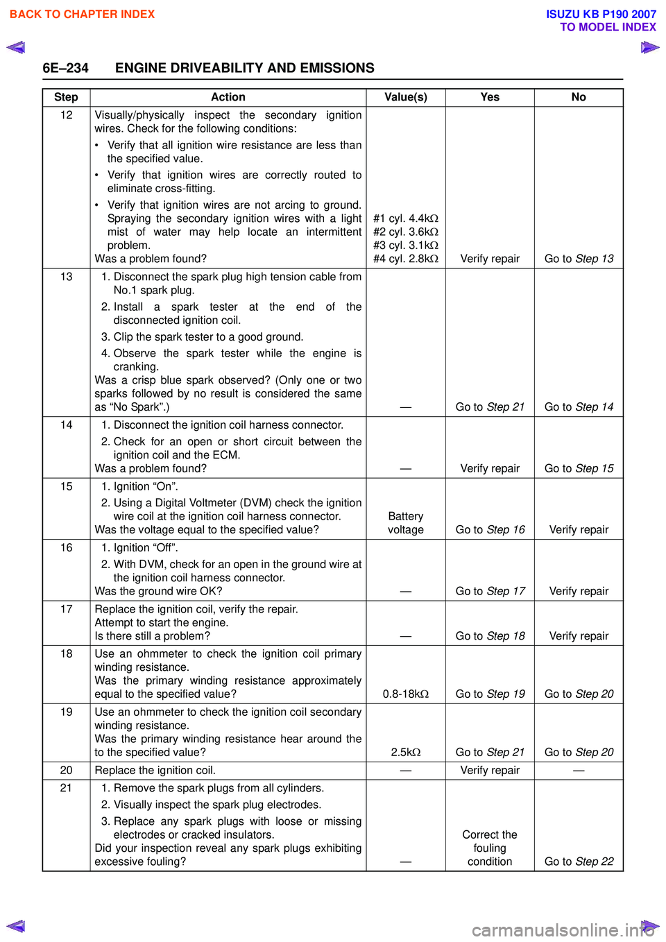
12 Visually/physically inspect the secondary ignitionwires. Check for the following conditions:
• Verify that all ignition wire resistance are less than the specified value.
• Verify that ignition wires are correctly routed to eliminate cross-fitting.
• Verify that ignition wires are not arcing to ground. Spraying the secondary ignition wires with a light
mist of water may help locate an intermittent
problem.
Was a problem found? #1 cyl. 4.4k
Ω
#2 cyl. 3.6k Ω
#3 cyl. 3.1k Ω
#4 cyl. 2.8k ΩVerify repair Go to Step 13
13 1. Disconnect the spark plug high tension cable from No.1 spark plug.
2. Install a spark tester at the end of the disconnected ignition coil.
3. Clip the spark tester to a good ground.
4. Observe the spark tester while the engine is cranking.
Was a crisp blue spark observed? (Only one or two
sparks followed by no result is considered the same
as “No Spark”.) — Go to Step 21Go to Step 14
14 1. Disconnect the ignition coil harness connector. 2. Check for an open or short circuit between theignition coil and the ECM.
Was a problem found? — Verify repair Go to Step 15
15 1. Ignition “On”. 2. Using a Digital Voltmeter (DVM) check the ignitionwire coil at the ignition coil harness connector.
Was the voltage equal to the specified value? Battery
voltage Go to Step 16Verify repair
16 1. Ignition “Off”. 2. With DVM, check for an open in the ground wire atthe ignition coil harness connector.
Was the ground wire OK? — Go to Step 17Verify repair
17 Replace the ignition coil, verify the repair. Attempt to start the engine.
Is there still a problem? — Go to Step 18Verify repair
18 Use an ohmmeter to check the ignition coil primary winding resistance.
Was the primary winding resistance approximately
equal to the specified value? 0.8-18kΩGo to Step 19 Go to Step 20
19 Use an ohmmeter to check the ignition coil secondary winding resistance.
Was the primary winding resistance hear around the
to the specified value? 2.5kΩ Go to Step 21 Go to Step 20
20 Replace the ignition coil. — Verify repair —
21 1. Remove the spark plugs from all cylinders. 2. Visually inspect the spark plug electrodes.
3. Replace any spark plugs with loose or missing electrodes or cracked insulators.
Did your inspection reveal any spark plugs exhibiting
excessive fouling? —Correct the
fouling
condition Go to Step 22
Step
Action Value(s) Yes No
BACK TO CHAPTER INDEX
TO MODEL INDEX
ISUZU KB P190 2007
Page 2407 of 6020
ENGINE DRIVEABILITY AND EMISSIONS 6E–237
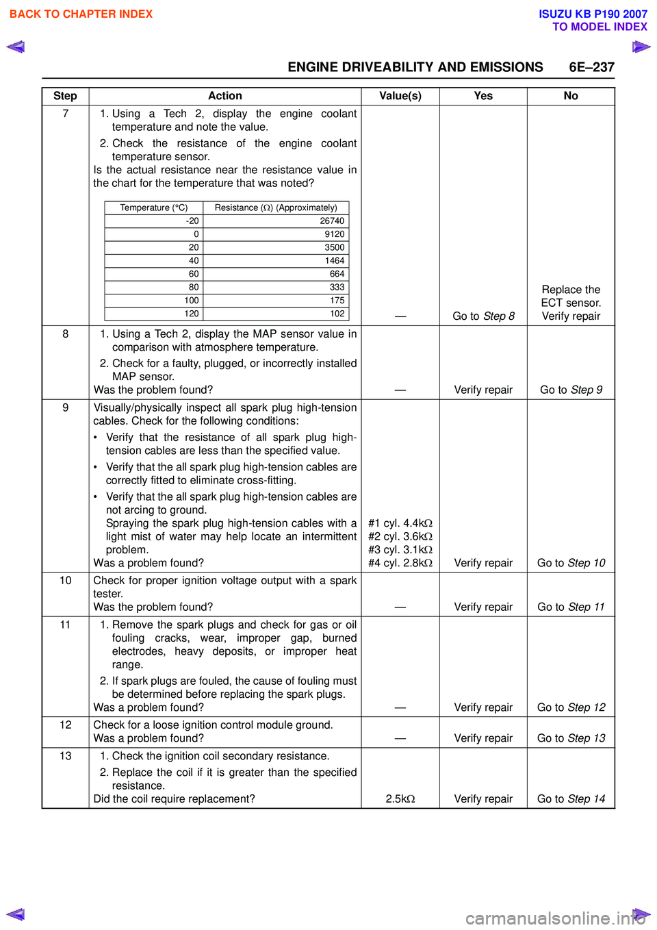
7 1. Using a Tech 2, display the engine coolanttemperature and note the value.
2. Check the resistance of the engine coolant temperature sensor.
Is the actual resistance near the resistance value in
the chart for the temperature that was noted?
—Go to Step 8Replace the
ECT sensor. Verify repair
8 1. Using a Tech 2, display the MAP sensor value in comparison with atmosphere temperature.
2. Check for a faulty, plugged, or incorrectly installed MAP sensor.
Was the problem found? — Verify repair Go to Step 9
9 Visually/physically inspect all spark plug high-tension cables. Check for the following conditions:
• Verify that the resistance of all spark plug high- tension cables are less than the specified value.
• Verify that the all spark plug high-tension cables are correctly fitted to eliminate cross-fitting.
• Verify that the all spark plug high-tension cables are not arcing to ground.
Spraying the spark plug high-tension cables with a
light mist of water may help locate an intermittent
problem.
Was a problem found? #1 cyl. 4.4k
Ω
#2 cyl. 3.6k Ω
#3 cyl. 3.1k Ω
#4 cyl. 2.8k ΩVerify repair Go to Step 10
10 Check for proper ignition voltage output with a spark tester.
Was the problem found? — Verify repair Go to Step 11
11 1. Remove the spark plugs and check for gas or oil fouling cracks, wear, improper gap, burned
electrodes, heavy deposits, or improper heat
range.
2. If spark plugs are fouled, the cause of fouling must be determined before replacing the spark plugs.
Was a problem found? — Verify repair Go to Step 12
12 Check for a loose ignition control module ground. Was a problem found? — Verify repair Go to Step 13
13 1. Check the ignition coil secondary resistance. 2. Replace the coil if it is greater than the specifiedresistance.
Did the coil require replacement? 2.5kΩ Verify repair Go to Step 14
Step
Action Value(s) Yes No
Temperature (°C) Resistance (Ω) (Approximately)
-20 26740
0 9120
20 3500
40 1464
60 664
80 333
100 175
120 102
BACK TO CHAPTER INDEX
TO MODEL INDEX
ISUZU KB P190 2007
Page 2410 of 6020
6E–240 ENGINE DRIVEABILITY AND EMISSIONS
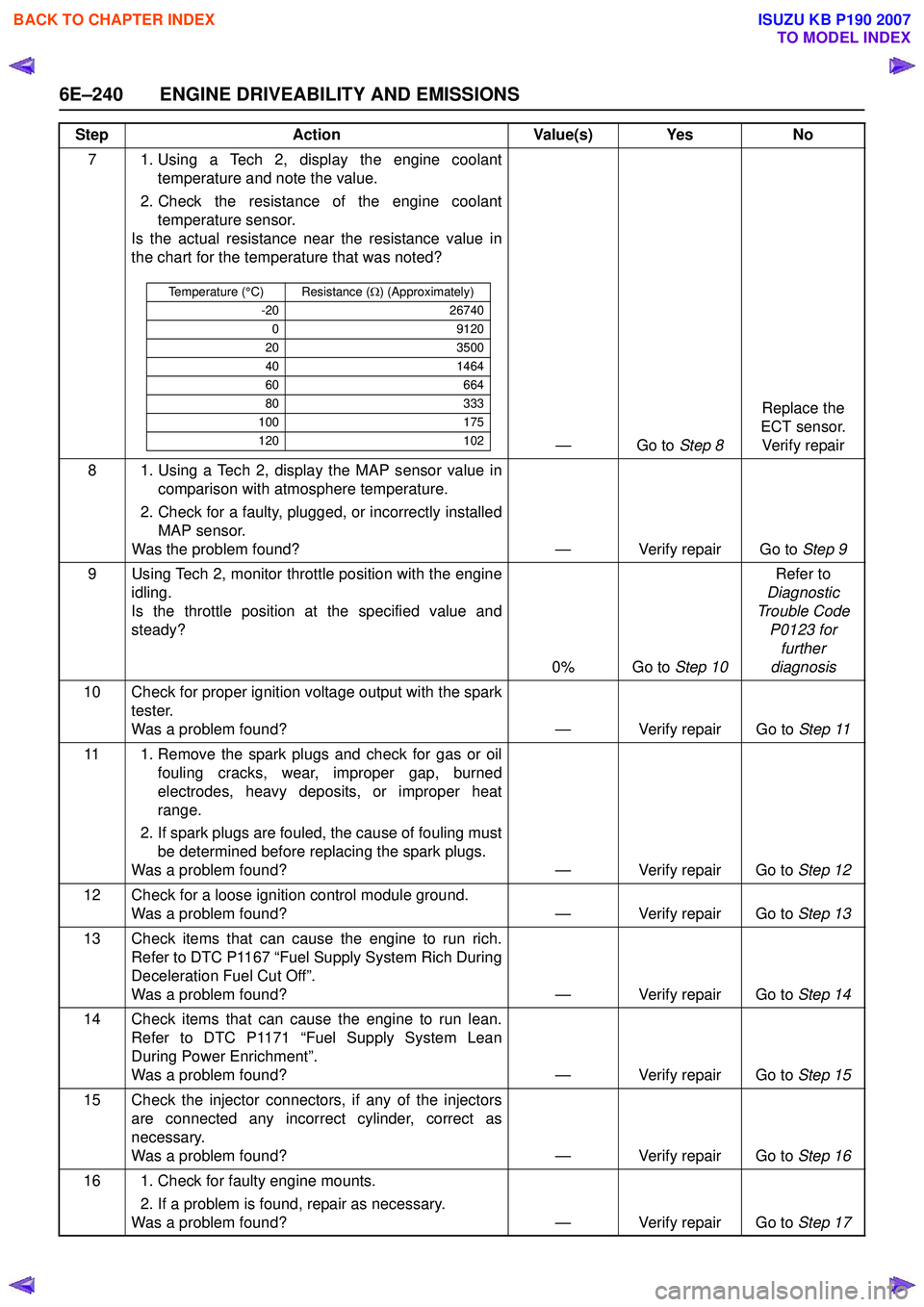
7 1. Using a Tech 2, display the engine coolanttemperature and note the value.
2. Check the resistance of the engine coolant temperature sensor.
Is the actual resistance near the resistance value in
the chart for the temperature that was noted?
—Go to Step 8Replace the
ECT sensor. Verify repair
8 1. Using a Tech 2, display the MAP sensor value in comparison with atmosphere temperature.
2. Check for a faulty, plugged, or incorrectly installed MAP sensor.
Was the problem found? — Verify repair Go to Step 9
9 Using Tech 2, monitor throttle position with the engine idling.
Is the throttle position at the specified value and
steady?
0% Go to Step 10Refer to
Diagnostic
Trouble Code P0123 for further
diagnosis
10 Check for proper ignition voltage output with the spark tester.
Was a problem found? — Verify repair Go to Step 11
11 1. Remove the spark plugs and check for gas or oil fouling cracks, wear, improper gap, burned
electrodes, heavy deposits, or improper heat
range.
2. If spark plugs are fouled, the cause of fouling must be determined before replacing the spark plugs.
Was a problem found? — Verify repair Go to Step 12
12 Check for a loose ignition control module ground. Was a problem found? — Verify repair Go to Step 13
13 Check items that can cause the engine to run rich. Refer to DTC P1167 “Fuel Supply System Rich During
Deceleration Fuel Cut Off”.
Was a problem found? — Verify repair Go to Step 14
14 Check items that can cause the engine to run lean. Refer to DTC P1171 “Fuel Supply System Lean
During Power Enrichment”.
Was a problem found? — Verify repair Go to Step 15
15 Check the injector connectors, if any of the injectors are connected any incorrect cylinder, correct as
necessary.
Was a problem found? — Verify repair Go to Step 16
16 1. Check for faulty engine mounts. 2. If a problem is found, repair as necessary.
Was a problem found? — Verify repair Go to Step 17
Step
Action Value(s) Yes No
Temperature (°C) Resistance (Ω) (Approximately)
-20 26740
0 9120
20 3500
40 1464
60 664
80 333
100 175
120 102
BACK TO CHAPTER INDEX
TO MODEL INDEX
ISUZU KB P190 2007
Page 2413 of 6020
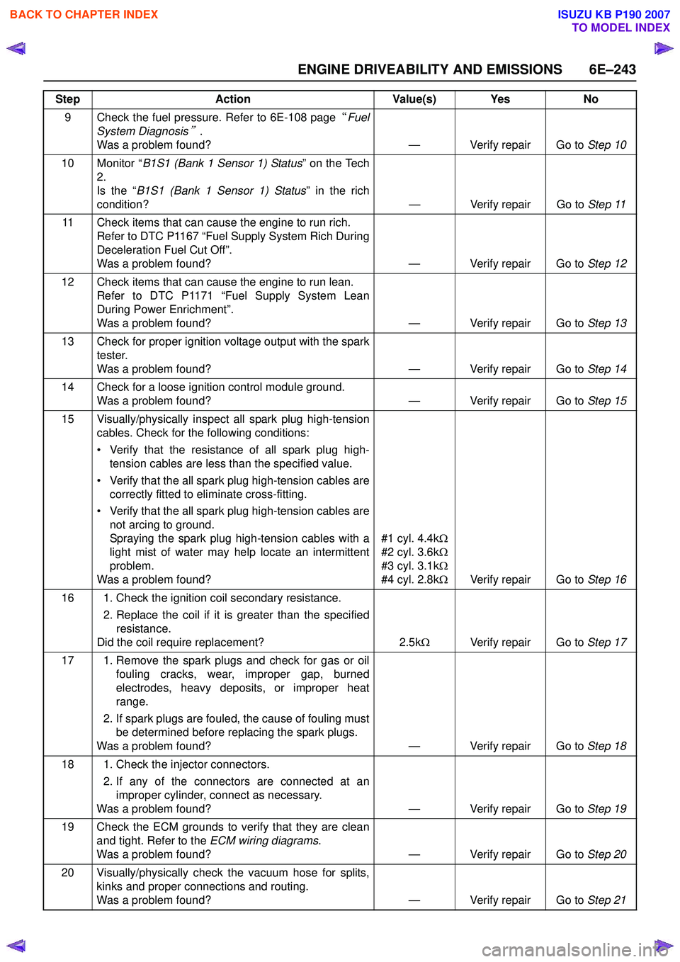
ENGINE DRIVEABILITY AND EMISSIONS 6E–243
9 Check the fuel pressure. Refer to 6E-108 page“Fuel
System Diagnosis
”.
Was a problem found? — Verify repair Go to Step 10
10 Monitor “ B1S1 (Bank 1 Sensor 1) Status ” on the Tech
2.
Is the “ B1S1 (Bank 1 Sensor 1) Status ” in the rich
condition? — Verify repair Go to Step 11
11 Check items that can cause the engine to run rich. Refer to DTC P1167 “Fuel Supply System Rich During
Deceleration Fuel Cut Off”.
Was a problem found? — Verify repair Go to Step 12
12 Check items that can cause the engine to run lean. Refer to DTC P1171 “Fuel Supply System Lean
During Power Enrichment”.
Was a problem found? — Verify repair Go to Step 13
13 Check for proper ignition voltage output with the spark tester.
Was a problem found? — Verify repair Go to Step 14
14 Check for a loose ignition control module ground. Was a problem found? — Verify repair Go to Step 15
15 Visually/physically inspect all spark plug high-tension cables. Check for the following conditions:
• Verify that the resistance of all spark plug high- tension cables are less than the specified value.
• Verify that the all spark plug high-tension cables are correctly fitted to eliminate cross-fitting.
• Verify that the all spark plug high-tension cables are not arcing to ground.
Spraying the spark plug high-tension cables with a
light mist of water may help locate an intermittent
problem.
Was a problem found? #1 cyl. 4.4k
Ω
#2 cyl. 3.6k Ω
#3 cyl. 3.1k Ω
#4 cyl. 2.8k ΩVerify repair Go to Step 16
16 1. Check the ignition coil secondary resistance. 2. Replace the coil if it is greater than the specifiedresistance.
Did the coil require replacement? 2.5kΩ Verify repair Go to Step 17
17 1. Remove the spark plugs and check for gas or oil fouling cracks, wear, improper gap, burned
electrodes, heavy deposits, or improper heat
range.
2. If spark plugs are fouled, the cause of fouling must be determined before replacing the spark plugs.
Was a problem found? — Verify repair Go to Step 18
18 1. Check the injector connectors. 2. If any of the connectors are connected at animproper cylinder, connect as necessary.
Was a problem found? — Verify repair Go to Step 19
19 Check the ECM grounds to verify that they are clean and tight. Refer to the ECM wiring diagrams.
Was a problem found? — Verify repair Go to Step 20
20 Visually/physically check the vacuum hose for splits, kinks and proper connections and routing.
Was a problem found? — Verify repair Go to Step 21
Step
Action Value(s) Yes No
BACK TO CHAPTER INDEX
TO MODEL INDEX
ISUZU KB P190 2007
Page 2416 of 6020
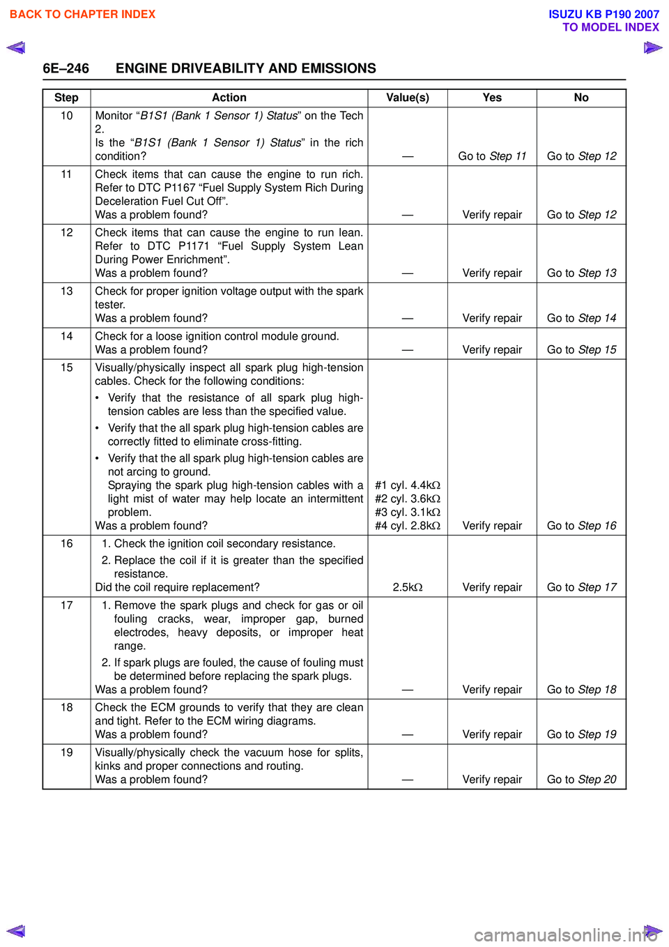
6E–246 ENGINE DRIVEABILITY AND EMISSIONS
10 Monitor “B1S1 (Bank 1 Sensor 1) Status ” on the Tech
2.
Is the “ B1S1 (Bank 1 Sensor 1) Status ” in the rich
condition? — Go to Step 11Go to Step 12
11 Check items that can cause the engine to run rich. Refer to DTC P1167 “Fuel Supply System Rich During
Deceleration Fuel Cut Off”.
Was a problem found? — Verify repair Go to Step 12
12 Check items that can cause the engine to run lean. Refer to DTC P1171 “Fuel Supply System Lean
During Power Enrichment”.
Was a problem found? — Verify repair Go to Step 13
13 Check for proper ignition voltage output with the spark tester.
Was a problem found? — Verify repair Go to Step 14
14 Check for a loose ignition control module ground. Was a problem found? — Verify repair Go to Step 15
15 Visually/physically inspect all spark plug high-tension cables. Check for the following conditions:
• Verify that the resistance of all spark plug high- tension cables are less than the specified value.
• Verify that the all spark plug high-tension cables are correctly fitted to eliminate cross-fitting.
• Verify that the all spark plug high-tension cables are not arcing to ground.
Spraying the spark plug high-tension cables with a
light mist of water may help locate an intermittent
problem.
Was a problem found? #1 cyl. 4.4k
Ω
#2 cyl. 3.6k Ω
#3 cyl. 3.1k Ω
#4 cyl. 2.8k ΩVerify repair Go to Step 16
16 1. Check the ignition coil secondary resistance. 2. Replace the coil if it is greater than the specifiedresistance.
Did the coil require replacement? 2.5kΩ Verify repair Go to Step 17
17 1. Remove the spark plugs and check for gas or oil fouling cracks, wear, improper gap, burned
electrodes, heavy deposits, or improper heat
range.
2. If spark plugs are fouled, the cause of fouling must be determined before replacing the spark plugs.
Was a problem found? — Verify repair Go to Step 18
18 Check the ECM grounds to verify that they are clean and tight. Refer to the ECM wiring diagrams.
Was a problem found? — Verify repair Go to Step 19
19 Visually/physically check the vacuum hose for splits, kinks and proper connections and routing.
Was a problem found? — Verify repair Go to Step 20
Step
Action Value(s) Yes No
BACK TO CHAPTER INDEX
TO MODEL INDEX
ISUZU KB P190 2007
Page 2419 of 6020
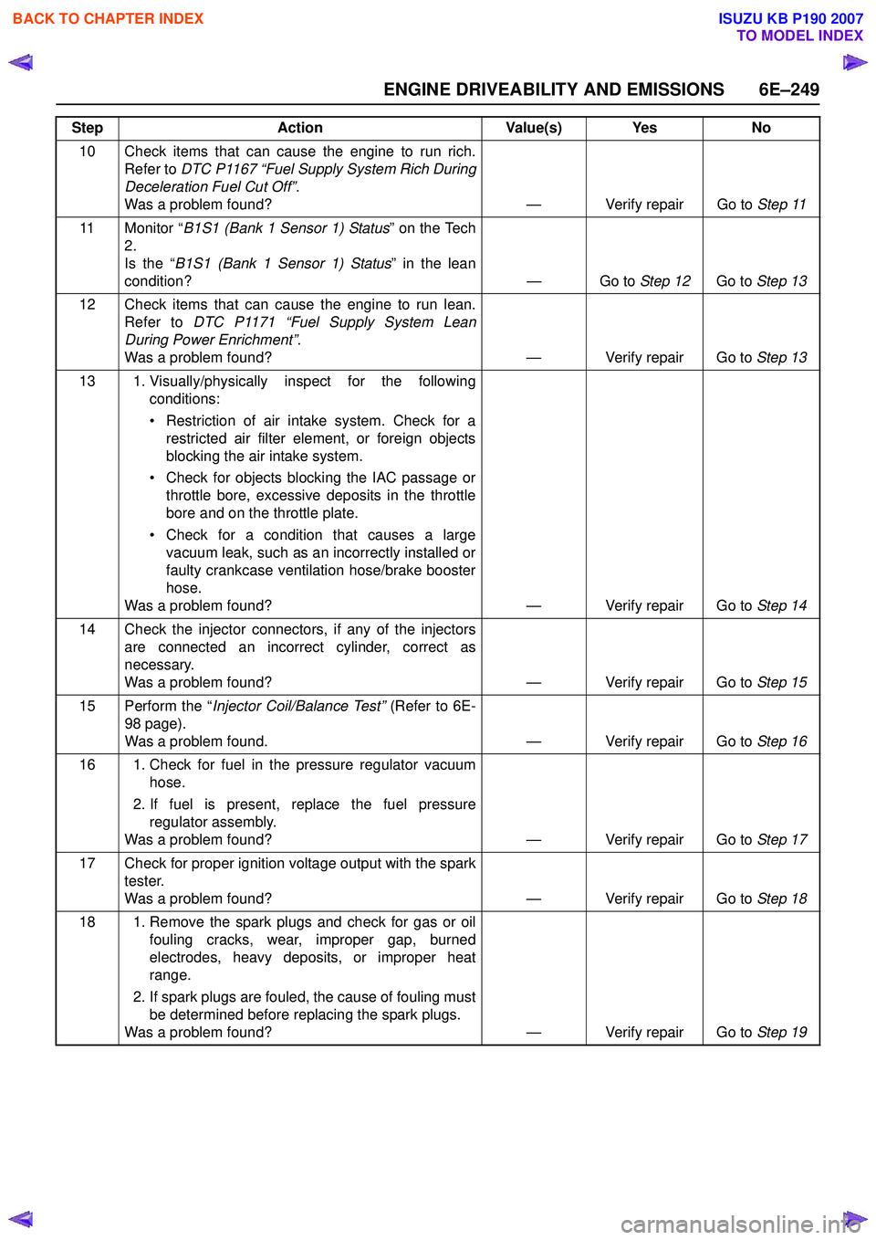
ENGINE DRIVEABILITY AND EMISSIONS 6E–249
10 Check items that can cause the engine to run rich.Refer to DTC P1167 “Fuel Supply System Rich During
Deceleration Fuel Cut Off” .
Was a problem found? — Verify repair Go to Step 11
11 Monitor “ B1S1 (Bank 1 Sensor 1) Status ” on the Tech
2.
Is the “ B1S1 (Bank 1 Sensor 1) Status ” in the lean
condition? — Go to Step 12Go to Step 13
12 Check items that can cause the engine to run lean. Refer to DTC P1171 “Fuel Supply System Lean
During Power Enrichment” .
Was a problem found? — Verify repair Go to Step 13
13 1. Visually/physically inspect for the following conditions:
• Restriction of air intake system. Check for a restricted air filter element, or foreign objects
blocking the air intake system.
• Check for objects blocking the IAC passage or throttle bore, excessive deposits in the throttle
bore and on the throttle plate.
• Check for a condition that causes a large vacuum leak, such as an incorrectly installed or
faulty crankcase ventilation hose/brake booster
hose.
Was a problem found? — Verify repair Go to Step 14
14 Check the injector connectors, if any of the injectors are connected an incorrect cylinder, correct as
necessary.
Was a problem found? — Verify repair Go to Step 15
15 Perform the “ Injector Coil/Balance Test” (Refer to 6E-
98 page).
Was a problem found. — Verify repair Go to Step 16
16 1. Check for fuel in the pressure regulator vacuum hose.
2. If fuel is present, replace the fuel pressure regulator assembly.
Was a problem found? — Verify repair Go to Step 17
17 Check for proper ignition voltage output with the spark tester.
Was a problem found? — Verify repair Go to Step 18
18 1. Remove the spark plugs and check for gas or oil fouling cracks, wear, improper gap, burned
electrodes, heavy deposits, or improper heat
range.
2. If spark plugs are fouled, the cause of fouling must be determined before replacing the spark plugs.
Was a problem found? — Verify repair Go to Step 19
Step
Action Value(s) Yes No
BACK TO CHAPTER INDEX
TO MODEL INDEX
ISUZU KB P190 2007