2007 ISUZU KB P190 change wheel
[x] Cancel search: change wheelPage 4468 of 6020
7A3-14 ON-VEHICLE SERVICE (JR405E)
Install or Connect
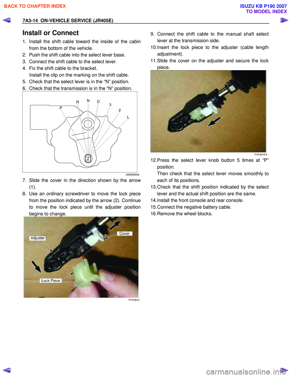
1. Install the shift cable toward the inside of the cabin
from the bottom of the vehicle.
2. Push the shift cable into the select lever base.
3. Connect the shift cable to the select lever.
4. Fix the shift cable to the bracket.
Install the clip on the marking on the shift cable.
5. Check that the select lever is in the “N” position.
6. Check that the transmission is in the “N” position.
249R300002
7. Slide the cover in the direction shown by the arrow
(1).
8. Use an ordinary screwdriver to move the lock piece from the position indicated by the arrow (2). Continue
to move the lock piece until the adjuster position
begins to change.
P1010012
9. Connect the shift cable to the manual shaft select
lever at the transmission side.
10. Insert the lock piece to the adjuster (cable length adjustment).
11. Slide the cover on the adjuster and secure the lock piece.
P1010016-2
12. Press the select lever knob button 5 times at “P”position.
Then check that the select lever moves smoothly to each of its positions.
13. Check that the shift position indicated by the select lever and the actual shift position are the same.
14. Install the front console and rear console.
15. Connect the negative battery cable.
16. Remove the wheel blocks.
BACK TO CHAPTER INDEX
TO MODEL INDEX
ISUZU KB P190 2007
Page 4471 of 6020
ON-VEHICLE SERVICE (JR405E) 7A3-17
Remove or Disconnect
1. Block the wheels.
2. Disconnect the negative battery cable.
3. Drain the fluid.
Refer to “ATF CHANGE” in this section.
4. Remove the 19 bolts and oil pan.
5. Inspect the bottom of the oil pan and strainer netting for foreign material (clutch facing and metal
shavings).
If there is an excessive accumulation of foreign material, the oil strainer must be replaced.
Further inspection is required to determine the source of the foreign material.
6. Remove the harness assembly (including the oil temperature sensor).
7. Remove the 11 bolts and the solenoid fixing plate.
8. Remove the 6 solenoids and 3 oil pressure switches.
Inspect
Oil pressure switch
Apply compressed air (390 kPa/4.0 kgf/cm2/57 psi) to
the oil pressure switch to check the oil pressure switch
continuity between the connector and screw.
Replace the oil pressure switch if the result of inspection
is abnormal.
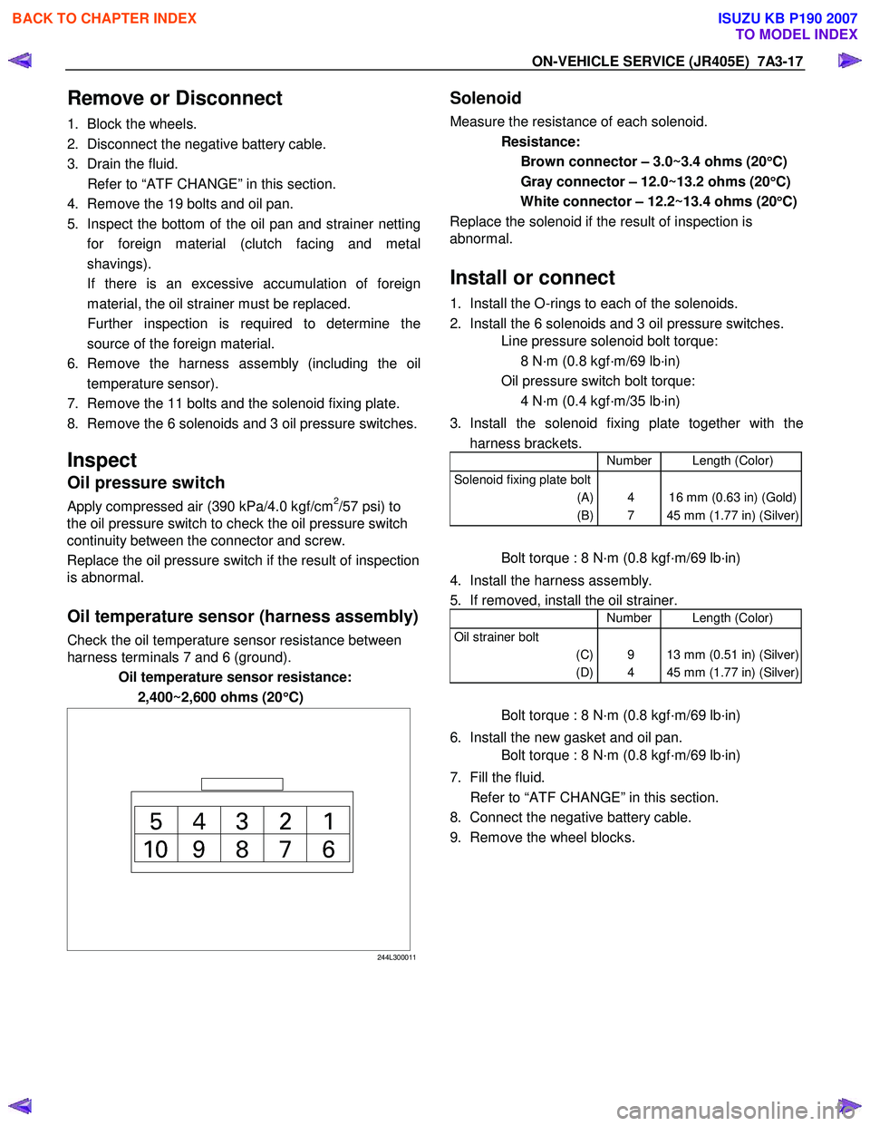
Oil temperature sensor (harness assembly)
Check the oil temperature sensor resistance between
harness terminals 7 and 6 (ground).
Oil temperature sensor resistance:
2,400~2,600 ohms (20 °
°°
°
C)
244L300011
Solenoid
Measure the resistance of each solenoid.
Resistance:
Brown connector – 3.0~3.4 ohms (20 °
°°
°
C)
Gray connector – 12.0~13.2 ohms (20 °
°°
°
C)
White connector – 12.2~13.4 ohms (20 °
°°
°
C)
Replace the solenoid if the result of inspection is
abnormal.
Install or connect
1. Install the O-rings to each of the solenoids.
2. Install the 6 solenoids and 3 oil pressure switches.
Line pressure solenoid bolt torque:
8 N·m (0.8 kgf·m/69 lb·in)
Oil pressure switch bolt torque:
4 N·m (0.4 kgf·m/35 lb·in)
3. Install the solenoid fixing plate together with the harness brackets.
Number Length (Color)
Solenoid fixing plate bolt
(A)
(B)
4
7
16 mm (0.63 in) (Gold)
45 mm (1.77 in) (Silver)
Bolt torque : 8 N·m (0.8 kgf·m/69 lb·in)
4. Install the harness assembly.
5. If removed, install the oil strainer.
Number Length (Color)
Oil strainer bolt
(C)
(D)
9
4
13 mm (0.51 in) (Silver)
45 mm (1.77 in) (Silver)
Bolt torque : 8 N·m (0.8 kgf·m/69 lb·in)
6. Install the new gasket and oil pan.
Bolt torque : 8 N·m (0.8 kgf·m/69 lb·in)
7. Fill the fluid.
Refer to “ATF CHANGE” in this section.
8. Connect the negative battery cable.
9. Remove the wheel blocks.
BACK TO CHAPTER INDEX
TO MODEL INDEX
ISUZU KB P190 2007
Page 4472 of 6020
7A3-18 ON-VEHICLE SERVICE (JR405E)
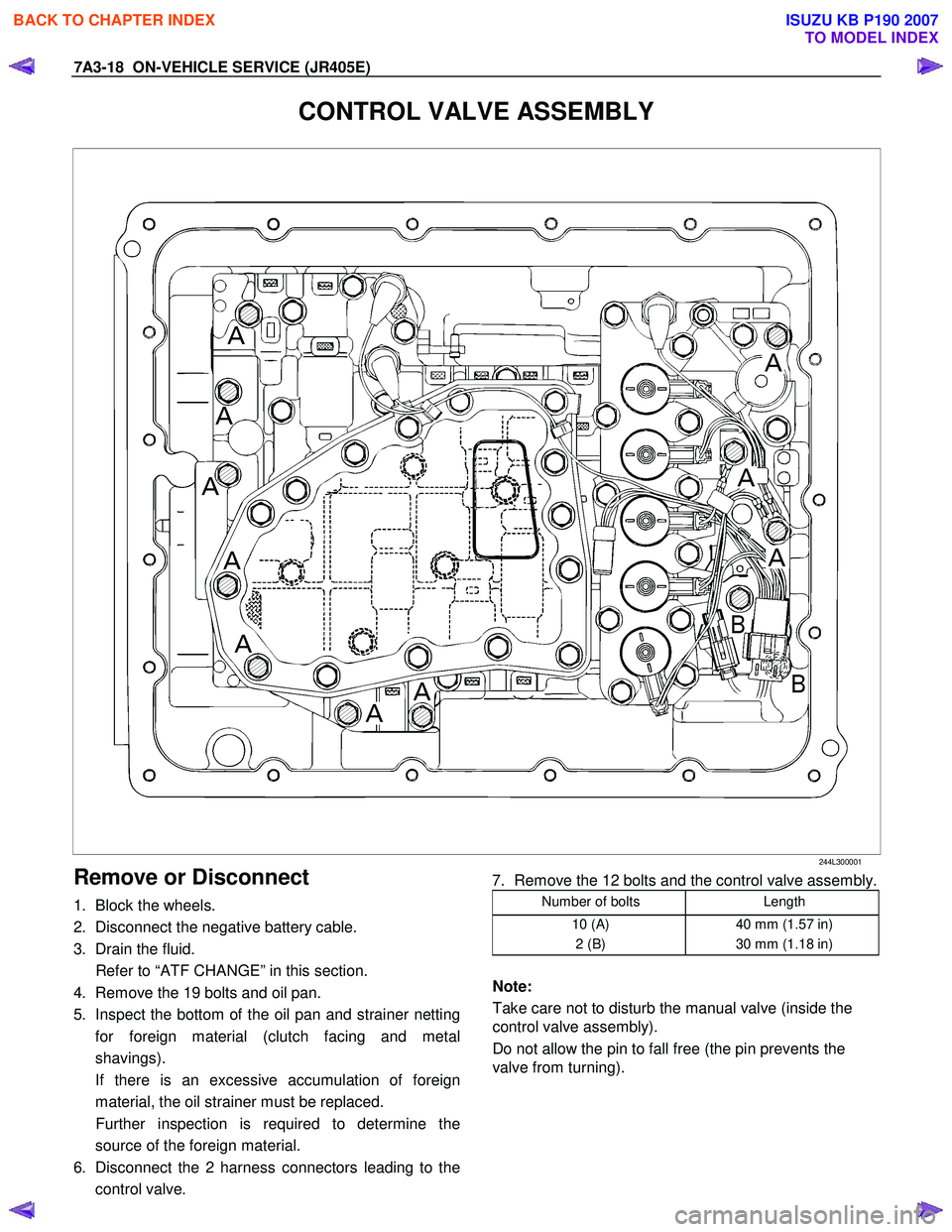
CONTROL VALVE ASSEMBLY
244L300001
Remove or Disconnect
1. Block the wheels.
2. Disconnect the negative battery cable.
3. Drain the fluid.
Refer to “ATF CHANGE” in this section.
4. Remove the 19 bolts and oil pan.
5. Inspect the bottom of the oil pan and strainer netting for foreign material (clutch facing and metal
shavings).
If there is an excessive accumulation of foreign material, the oil strainer must be replaced.
Further inspection is required to determine the source of the foreign material.
6. Disconnect the 2 harness connectors leading to the control valve.
7. Remove the 12 bolts and the control valve assembly.
Number of bolts Length
10 (A)
2 (B) 40 mm (1.57 in)
30 mm (1.18 in)
Note:
Take care not to disturb the manual valve (inside the
control valve assembly).
Do not allow the pin to fall free (the pin prevents the
valve from turning).
BACK TO CHAPTER INDEX
TO MODEL INDEX
ISUZU KB P190 2007
Page 4473 of 6020
ON-VEHICLE SERVICE (JR405E) 7A3-19
Install or Connect
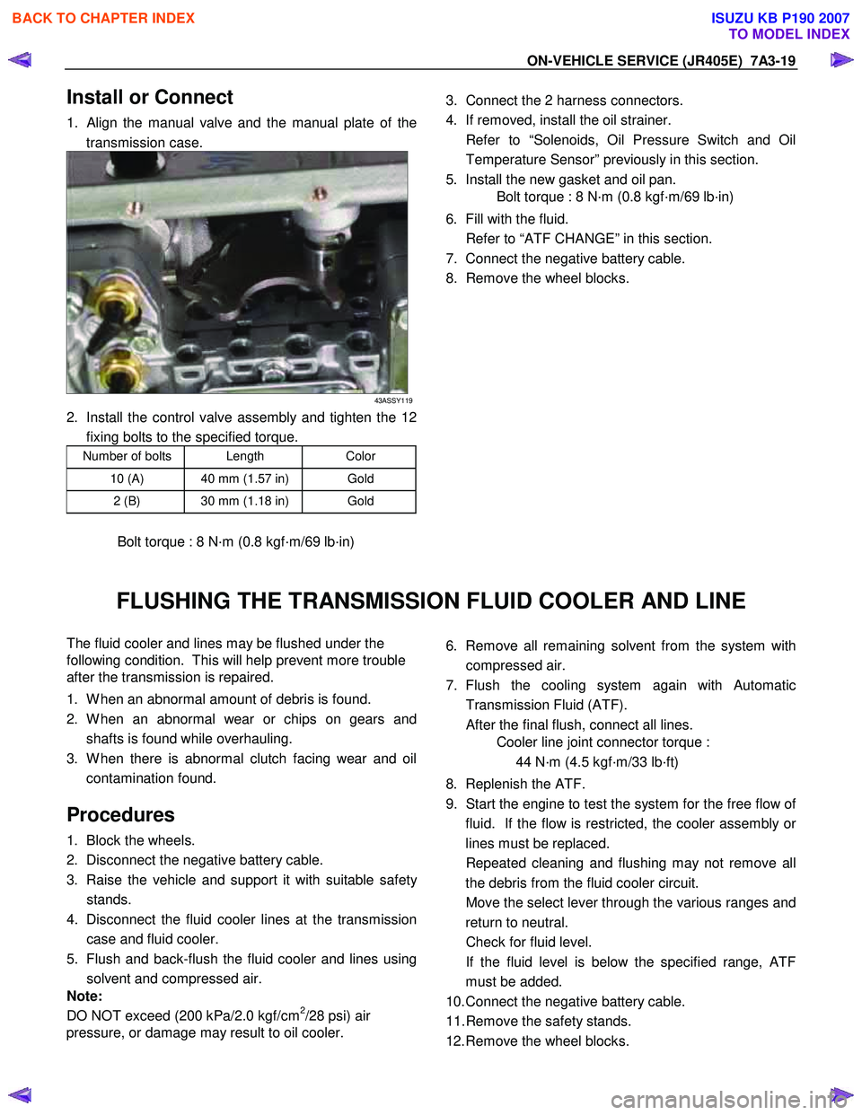
1. Align the manual valve and the manual plate of the
transmission case.
43ASSY119
2. Install the control valve assembly and tighten the 12 fixing bolts to the specified torque.
Number of bolts Length Color
10 (A) 40 mm (1.57 in) Gold
2 (B) 30 mm (1.18 in) Gold
Bolt torque : 8 N·m (0.8 kgf·m/69 lb·in)
3. Connect the 2 harness connectors.
4. If removed, install the oil strainer.
Refer to “Solenoids, Oil Pressure Switch and Oil Temperature Sensor” previously in this section.
5. Install the new gasket and oil pan.
Bolt torque : 8 N·m (0.8 kgf·m/69 lb·in)
6. Fill with the fluid.
Refer to “ATF CHANGE” in this section.
7. Connect the negative battery cable.
8. Remove the wheel blocks.
FLUSHING THE TRANSMISSION FLUID COOLER AND LINE
The fluid cooler and lines may be flushed under the
following condition. This will help prevent more trouble
after the transmission is repaired.
1. W hen an abnormal amount of debris is found.
2. W hen an abnormal wear or chips on gears and shafts is found while overhauling.
3. W hen there is abnormal clutch facing wear and oil contamination found.
Procedures
1. Block the wheels.
2. Disconnect the negative battery cable.
3. Raise the vehicle and support it with suitable safet
y
stands.
4. Disconnect the fluid cooler lines at the transmission case and fluid cooler.
5. Flush and back-flush the fluid cooler and lines using solvent and compressed air.
Note:
DO NOT exceed (200 kPa/2.0 kgf/cm
2/28 psi) air
pressure, or damage may result to oil cooler.
6. Remove all remaining solvent from the system with
compressed air.
7. Flush the cooling system again with Automatic Transmission Fluid (ATF).
After the final flush, connect all lines.
Cooler line joint connector torque :
44 N·m (4.5 kgf·m/33 lb·ft)
8. Replenish the ATF.
9. Start the engine to test the system for the free flow o
f
fluid. If the flow is restricted, the cooler assembly o
r
lines must be replaced.
Repeated cleaning and flushing may not remove all the debris from the fluid cooler circuit.
Move the select lever through the various ranges and return to neutral.
Check for fluid level.
If the fluid level is below the specified range, ATF must be added.
10. Connect the negative battery cable.
11. Remove the safety stands.
12. Remove the wheel blocks.
BACK TO CHAPTER INDEX
TO MODEL INDEX
ISUZU KB P190 2007
Page 4723 of 6020

7B1-4 Manual Transmission (MUX)
Troubleshooting
ConditionPossible Cause Correction
Abnormal Noise (Noisy in Neutral) Insufficient or improper lubricant Replenish or replace lubricant Flywheel pilot bearing worn or
broken Replace flywheel pilot bearing
Bearing(s) worn or broken (Input
shaft, counter shaft, and output
shaft) Replace bearing(s)
Gear tooth contact surfaces worn or
scuffed (Input shaft, counter shaft,
output shaft, and reverse idler gear) Replace gear(s)
Spline worn (Input shaft, output
shaft, counter shaft, and
synchronizer clutch hub) Replace worn parts
Transmission misalignment Realign transmission
Abnormal Noise (Noisy Operation) Insufficient or improper lubricant (Metallic rattling) Replenish or replace lubricant
Bearing(s) worn or broken (Hissing,
thumping, or bumping) Replace bearing(s)
Gear(s) worn, chipped, or cracked
(Growling, humming, or grinding) Replace gear(s)
Gears seizing on thrust face or
inner face free running (Squealing
at high speeds) Replace gear(s)
Gears lack of backlash between
meshing (Gear whining) Replace gear(s)
Hard Shifting Insufficient or improper lubricant Replenish or replace lubricant
Improper clutch pedal free play Readjust clutch pedal free play
Hard operating of change lever
caused insufficient grease Repair or regrease change lever
assembly
Change lever sliding portions worn Repair or replace applicable parts and regrease
Shift block sleeve movement failure Repair or replace sleeve
Shift rod and/or quadrant box
sliding face worn Replace worn parts
Shift arm and/or synchronizer
sleeve groove worn Replace worn parts
Collar, and/or gear thrust faces
worn (Input shaft and counter shaft
thrust play) Replace worn parts
Synchronizer parts worn Replace worn parts
BACK TO CHAPTER INDEX
TO MODEL INDEX
ISUZU KB P190 2007
Page 4920 of 6020
7D1-46 TRANSFER CONTROL SYSTEM
Diagnosis
Before determining a trouble (Non-trouble mode)
1. When shifting from 2H to 4H:
1-1-1 When the flashing frequency of the 4WD indicator is changed from 2Hz to 4Hz (Shift on the fly) If the load is too large to shift the gears synchronously, the operation is repeated up to 3 times. If the shifting
is not effected after being repeated 3 times, the indicator frequency is changed from 2Hz to 4Hz. At the same
time, the actuator condition is changed to 2H, indicator flashes at 4Hz for 10 seconds, and then goes out.
Cause of excessive synchronous shifting load
• Extremely low temperature (the oil viscosity of the front differential increases requiring a large load for
synchronization).
• High speed (since the difference of relative revolutions of gears to be shifted synchronously is too large,
required work load per unit time becomes larger).
Step 1-1-1:
Stop the vehicle or decrease the speed and operate as required again.
1-1-2 When the flashing frequency of the 4WD indicator is changed from 2Hz to 4Hz (Rigid and free wheel
Hub) / Block out of meshing spline in transfer case.
Step 1-1-2:
Run the vehicle forward and backward several meters and operate as required again.
1-2 When the flashing of 4WD indicator at 2Hz continues more than 11.5 seconds (repetition of 3 times of
above No.1 is counted) (Shift on the fly)
If there is difference of revolutions and phases between the front wheel and the axle, connecting the front
wheel and axle is difficult.
Until shifting in the transfer and connection of the front wheel and axle are completed
∗, the indicator flashes at
a frequency of 2Hz. In the above case, the indicator continues flashing at a frequency of 2Hz until the
connection of the front axle is completed. (If the shifting in the transfer is not completed, the flashing
frequency is changed to 4Hz (above No.1).)
By correcting the difference of relative revolutions and deviation of phases, the shifting can be completed.
Step 1-2:
While the vehicle is running, check it is safe around the vehicle and then accelerate or decelerate the
vehicle while going straight.
When the vehicle is at a stop, run the vehicle forward and backward several meters.
2. When shifting from 4H to 2H
2-1 When 4WD indicator continues flashing at 2Hz
W hen shifting from 4H to 2H, the 4W D indicator continues flashing at 2Hz until separation in the transfer and
the separation of the front wheel axle are completed∗. W hen torsional torque is accumulated in the drive
system, separation in the transfer and separation of the front axle∗ is difficult. In such a case, they can be
separated by removing the torsional torque of the drive system.
Step 2-1:
While the vehicle is running, check it is safe around the vehicle and then accelerate or decelerate the
vehicle while going straight.
When the vehicle is in stop, run the vehicle several meters forward and backward.
∗: Shift on the fly only.
BACK TO CHAPTER INDEX
TO MODEL INDEX
ISUZU KB P190 2007
Page 5137 of 6020
ELECTRICAL-BODY AND CHASSIS 8A-199
HEADLIGHT LEVELING SWITCH
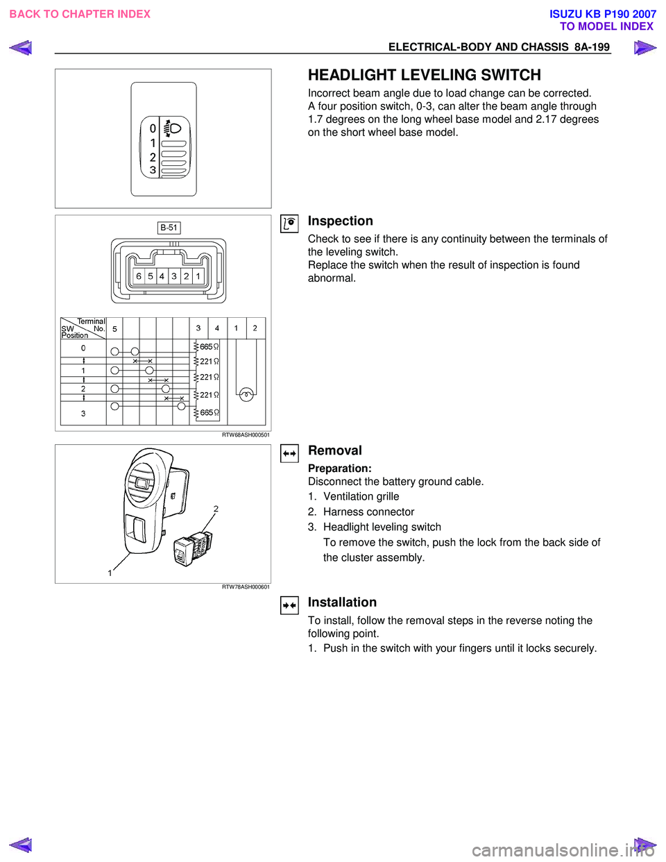
Incorrect beam angle due to load change can be corrected.
A four position switch, 0-3, can alter the beam angle through
1.7 degrees on the long wheel base model and 2.17 degrees
on the short wheel base model.
RTW 68ASH000501
Inspection
Check to see if there is any continuity between the terminals of
the leveling switch.
Replace the switch when the result of inspection is found
abnormal.
RTW 78ASH000601
Removal
Preparation:
Disconnect the battery ground cable.
1. Ventilation grille
2. Harness connector
3. Headlight leveling switch To remove the switch, push the lock from the back side of
the cluster assembly.
Installation
To install, follow the removal steps in the reverse noting the
following point.
1. Push in the switch with your fingers until it locks securely.
BACK TO CHAPTER INDEX TO MODEL INDEXISUZU KB P190 2007