2007 ISUZU KB P190 change wheel
[x] Cancel search: change wheelPage 1298 of 6020
6E-264 Engine Control System (4JH1)
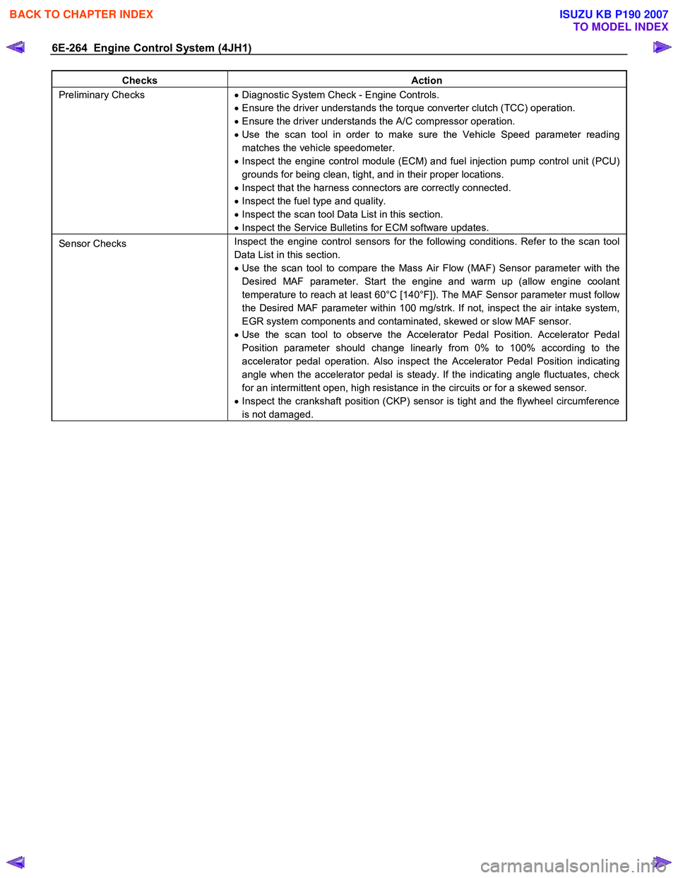
Checks Action
Preliminary Checks • Diagnostic System Check - Engine Controls.
• Ensure the driver understands the torque converter clutch (TCC) operation.
• Ensure the driver understands the A/C compressor operation.
• Use the scan tool in order to make sure the Vehicle Speed parameter reading
matches the vehicle speedometer.
• Inspect the engine control module (ECM) and fuel injection pump control unit (PCU)
grounds for being clean, tight, and in their proper locations.
• Inspect that the harness connectors are correctly connected.
• Inspect the fuel type and quality.
• Inspect the scan tool Data List in this section.
• Inspect the Service Bulletins for ECM software updates.
Sensor Checks Inspect the engine control sensors for the following conditions. Refer to the scan tool
Data List in this section.
• Use the scan tool to compare the Mass Air Flow (MAF) Sensor parameter with the
Desired MAF parameter. Start the engine and warm up (allow engine coolant
temperature to reach at least 60°C [140°F]). The MAF Sensor parameter must follow
the Desired MAF parameter within 100 mg/strk. If not, inspect the air intake system,
EGR system components and contaminated, skewed or slow MAF sensor.
• Use the scan tool to observe the Accelerator Pedal Position. Accelerator Pedal
Position parameter should change linearly from 0% to 100% according to the
accelerator pedal operation. Also inspect the Accelerator Pedal Position indicating
angle when the accelerator pedal is steady. If the indicating angle fluctuates, check
for an intermittent open, high resistance in the circuits or for a skewed sensor.
• Inspect the crankshaft position (CKP) sensor is tight and the flywheel circumference
is not damaged.
BACK TO CHAPTER INDEX
TO MODEL INDEX
ISUZU KB P190 2007
Page 1304 of 6020

6E-270 Engine Control System (4JH1)
Checks Action
Engine Mechanical Check Inspect the engine mechanical for the following conditions. Refer to the Engine
Mechanical section.
• Inspect for poor cylinder compression. Proper compression is more than 2100 kPa
(309 psi).
• Improper mechanical timing
• Improper valve gap
• Broken or weak valve springs
• W orn camshaft lobes
Additional Checks •
Inspect the generator output voltage. Repair if less than 9 volts or more than 16
volts.
• Inspect the EGR system operating correctly.
• Inspect the A/C operation.
• Inspect the torque converter clutch (TCC) operation.
Fuel Knock/Combustion Noise
Checks Action
DEFINITION:A mild to severe ping, usually worse under acceleration. The engine makes sharp metallic knocks that change
with the throttle opening.
Preliminary Checks • Diagnostic System Check - Engine Controls.
• Ensure the vehicle has an actual problem.
• Inspect for smoke associated with the combustion noise.
• Inspect the fuel quality (cetane index).
• Inspect the scan tool Data List in this section.
• Inspect the Service Bulletins for ECM software updates.
Sensor Checks Inspect the engine control sensors for the following conditions. Refer to the scan tool
Data List in this section.
• Use the scan tool to compare the Engine Coolant Temperature (ECT) with the Intake
Air Temperature (IAT) and Fuel Temperature (FT) on a cold engine condition. If the
difference among temperature reading is more than 5°C (9°F) on a cold engine,
check for high resistance on the low reference circuit and signal circuit or for a
skewed sensor.
Notice: The mass air flow (MAF) sensor is heated and as a result the IAT sensor may
indicate a higher than normal intake air temperature if the ignition switch is being ON.
FT sensor is internal to the PCU and it is part of the fuel injection pump assembly.
• Use the scan tool to compare the MAF Sensor parameter with the Desired MAF
parameter. Start the engine and warm up (allow engine coolant temperature to reach
at least 60°C [140°F]). The MAF Sensor parameter must follow the Desired MAF
parameter within 100 mg/strk. If not, inspect the air intake system, EGR system
components and contaminated, skewed or slow MAF sensor.
• Inspect the crankshaft position (CKP) sensor is tight and the flywheel circumference
is not damaged.
Fuel System Checks •
If excessive smoke is present, check for an injection nozzle(s).Remove each glow
plug from the cylinder head and inspect the tip of the glow plugs for wet by fuel. Use
the cylinder compression gauge. Proper compression is more than 2100 kPa (309
psi). If poor compression is observed, inspect the engine mechanical.
• Inspect the fuel injection nozzle(s) for proper splay condition or operating pressure.
Notice: Only first stage of operating pressure can be checked.
• Inspect the timing device operating correctly. Observe the Actual Injection Timing
parameter with the scan tool while running the engine. The Actual Injection Timing
parameter must follow the Desired Injection Timing within 2°CA on each engine
speed. Engine idle > around 2000 RPM> around 3000 RPM. If not, inspect the fuel
system restriction, air in the fuel or fuel injection pump operation.
BACK TO CHAPTER INDEX
TO MODEL INDEX
ISUZU KB P190 2007
Page 1332 of 6020
6E-298 Engine Control System (4JH1)
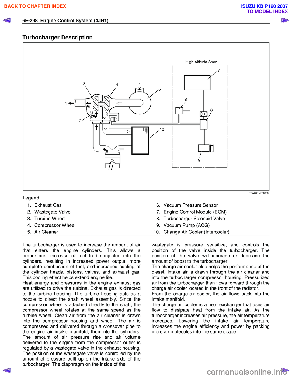
Turbocharger Description
RTW 66EMF000501
Legend
1. Exhaust Gas
2. W astegate Valve
3. Turbine W heel
4. Compressor W heel
5. Air Cleaner
6. Vacuum Pressure Sensor
7. Engine Control Module (ECM)
8. Turbocharger Solenoid Valve
9. Vacuum Pump (ACG)
10. Change Air Cooler (Intercooler)
The turbocharger is used to increase the amount of ai
r
that enters the engine cylinders. This allows a
proportional increase of fuel to be injected into the
cylinders, resulting in increased power output, more
complete combustion of fuel, and increased cooling o
f
the cylinder heads, pistons, valves, and exhaust gas.
This cooling effect helps extend engine life.
Heat energy and pressures in the engine exhaust gas
are utilized to drive the turbine. Exhaust gas is directed
to the turbine housing. The turbine housing acts as a
nozzle to direct the shaft wheel assembly. Since the
compressor wheel is attached directly to the shaft, the
compressor wheel rotates at the same speed as the
turbine wheel. Clean air from the air cleaner is drawn
into the compressor housing and wheel. The air is
compressed and delivered through a crossover pipe to
the engine air intake manifold, then into the cylinders.
The amount of air pressure rise and air volume
delivered to the engine from the compressor outlet is
regulated by a wastegate valve in the exhaust housing.
The position of the wastegate valve is controlled by the
amount of pressure built up on the intake side of the
turbocharger. The diaphragm on the inside of the
wastegate is pressure sensitive, and controls the
position of the valve inside the turbocharger. The
position of the valve will increase or decrease the
amount of boost to the turbocharger.
The charge air cooler also helps the performance of the
diesel. Intake air is drawn through the air cleaner and
into the turbocharger compressor housing. Pressurized
air from the turbocharger then flows forward through the
charge air cooler located in the front of the radiator.
From the charge air cooler, the air flows back into the
intake manifold.
The charge air cooler is a heat exchanger that uses ai
r
flow to dissipate heat from the intake air. As the
turbocharger increases air pressure, the air temperature
increases. Lowering the intake air temperature
increases the engine efficiency and power by packing
more air molecules into the same space.
BACK TO CHAPTER INDEX
TO MODEL INDEX
ISUZU KB P190 2007
Page 1473 of 6020
ENGINE MECHANICAL (4JK1/4JJ1) 6A-113
Inspection
1. Visual inspection
• Inspect the flywheel friction surface for cracks
and damages, and replace it if it has
abnormality.
• Inspect the tooth part of the ring gear, replace
the ring gear if it has damage or serious wear.
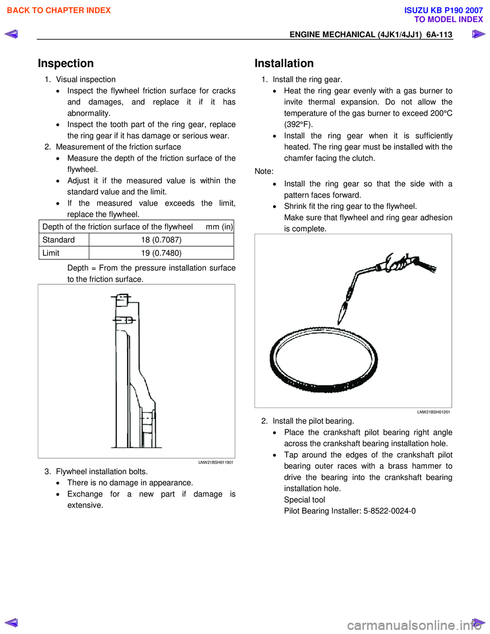
2. Measurement of the friction surface • Measure the depth of the friction surface of the
flywheel.
•
Adjust it if the measured value is within the
standard value and the limit.
• If the measured value exceeds the limit,
replace the flywheel.
Depth of the friction surface of the flywheel mm (in)
Standard 18 (0.7087)
Limit 19 (0.7480)
Depth = From the pressure installation surface
to the friction surface.
LNW 21BSH011901
3. Flywheel installation bolts.
• There is no damage in appearance.
• Exchange for a new part if damage is
extensive.
Installation
1. Install the ring gear.
• Heat the ring gear evenly with a gas burner to
invite thermal expansion. Do not allow the
temperature of the gas burner to exceed 200°C
(392°F).
• Install the ring gear when it is sufficientl
y
heated. The ring gear must be installed with the
chamfer facing the clutch.
Note: • Install the ring gear so that the side with a
pattern faces forward.
• Shrink fit the ring gear to the flywheel.
Make sure that flywheel and ring gear adhesion is complete.
LNW 21BSH01201
2. Install the pilot bearing.
• Place the crankshaft pilot bearing right angle
across the crankshaft bearing installation hole.
• Tap around the edges of the crankshaft pilot
bearing outer races with a brass hammer to
drive the bearing into the crankshaft bearing
installation hole.
Special tool
Pilot Bearing Installer: 5-8522-0024-0
BACK TO CHAPTER INDEX
TO MODEL INDEX
ISUZU KB P190 2007
Page 1582 of 6020
FUEL SYSTEM (4JK1/4JJ1) 6C-41
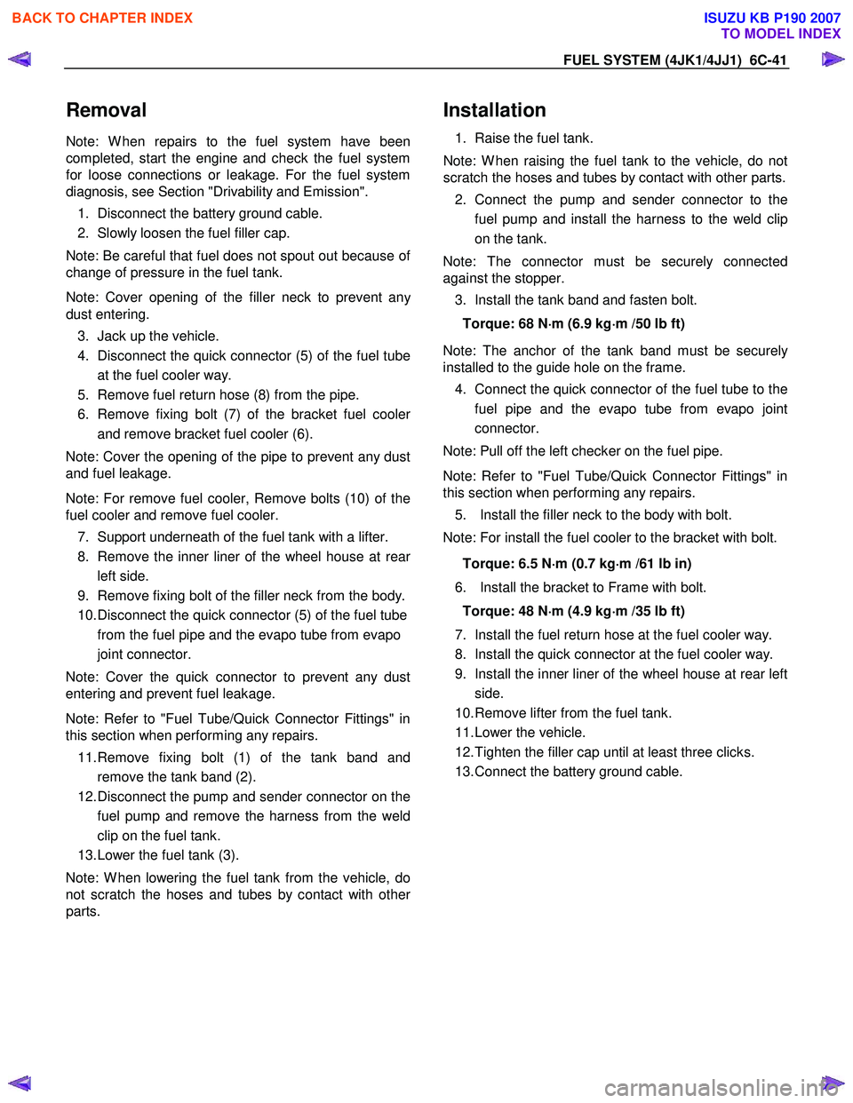
Removal
Note: W hen repairs to the fuel system have been
completed, start the engine and check the fuel system
for loose connections or leakage. For the fuel system
diagnosis, see Section "Drivability and Emission".
1. Disconnect the battery ground cable.
2. Slowly loosen the fuel filler cap.
Note: Be careful that fuel does not spout out because o
f
change of pressure in the fuel tank.
Note: Cover opening of the filler neck to prevent an
y
dust entering. 3. Jack up the vehicle.
4. Disconnect the quick connector (5) of the fuel tube at the fuel cooler way.
5. Remove fuel return hose (8) from the pipe.
6. Remove fixing bolt (7) of the bracket fuel coole
r
and remove bracket fuel cooler (6).
Note: Cover the opening of the pipe to prevent any dust
and fuel leakage.
Note: For remove fuel cooler, Remove bolts (10) of the
fuel cooler and remove fuel cooler.
7. Support underneath of the fuel tank with a lifter.
8. Remove the inner liner of the wheel house at rea
r
left side.
9. Remove fixing bolt of the filler neck from the body.
10. Disconnect the quick connector (5) of the fuel tube from the fuel pipe and the evapo tube from evapo
joint connector.
Note: Cover the quick connector to prevent any dust
entering and prevent fuel leakage.
Note: Refer to "Fuel Tube/Quick Connector Fittings" in
this section when performing any repairs.
11. Remove fixing bolt (1) of the tank band and remove the tank band (2).
12. Disconnect the pump and sender connector on the fuel pump and remove the harness from the weld
clip on the fuel tank.
13. Lower the fuel tank (3).
Note: W hen lowering the fuel tank from the vehicle, do
not scratch the hoses and tubes by contact with othe
r
parts.
Installation
1. Raise the fuel tank.
Note: W hen raising the fuel tank to the vehicle, do not
scratch the hoses and tubes by contact with other parts.
2. Connect the pump and sender connector to the fuel pump and install the harness to the weld clip
on the tank.
Note: The connector must be securely connected
against the stopper.
3. Install the tank band and fasten bolt.
Torque: 68 N ⋅
⋅⋅
⋅
m (6.9 kg ⋅
⋅⋅
⋅
m /50 lb ft)
Note: The anchor of the tank band must be securely
installed to the guide hole on the frame.
4. Connect the quick connector of the fuel tube to the fuel pipe and the evapo tube from evapo joint
connector.
Note: Pull off the left checker on the fuel pipe.
Note: Refer to "Fuel Tube/Quick Connector Fittings" in
this section when performing any repairs.
5. Install the filler neck to the body with bolt.
Note: For install the fuel cooler to the bracket with bolt.
Torque: 6.5 N ⋅
⋅⋅
⋅
m (0.7 kg ⋅
⋅⋅
⋅
m /61 lb in)
6. Install the bracket to Frame with bolt. Torque: 48 N ⋅
⋅⋅
⋅
m (4.9 kg ⋅
⋅⋅
⋅
m /35 lb ft)
7. Install the fuel return hose at the fuel cooler way.
8. Install the quick connector at the fuel cooler way.
9. Install the inner liner of the wheel house at rear left side.
10. Remove lifter from the fuel tank.
11. Lower the vehicle.
12. Tighten the filler cap until at least three clicks.
13. Connect the battery ground cable.
BACK TO CHAPTER INDEX
TO MODEL INDEX
ISUZU KB P190 2007
Page 1962 of 6020
ENGINE CONTROL SYSTEM (4JK1/4JJ1) 6E-345
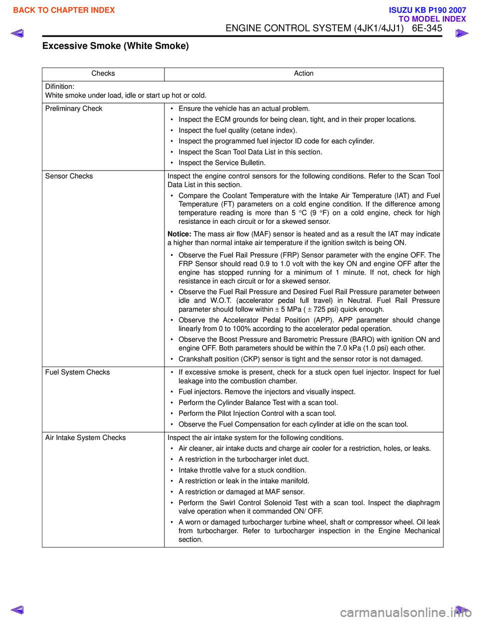
Excessive Smoke (White Smoke)
ChecksAction
Difinition:
White smoke under load, idle or start up hot or cold.
Preliminary Check • Ensure the vehicle has an actual problem.
• Inspect the ECM grounds for being clean, tight, and in their proper locations.
• Inspect the fuel quality (cetane index).
• Inspect the programmed fuel injector ID code for each cylinder.
• Inspect the Scan Tool Data List in this section.
• Inspect the Service Bulletin.
Sensor Checks Inspect the engine control sensors for the following conditions. Refer to the Scan Tool
Data List in this section.
• Compare the Coolant Temperature with the Intake Air Temperature (IAT) and Fuel Temperature (FT) parameters on a cold engine condition. If the difference among
temperature reading is more than 5 °C (9 °F) on a cold engine, check for high
resistance in each circuit or for a skewed sensor.
Notice: The mass air flow (MAF) sensor is heated and as a result the IAT may indicate
a higher than normal intake air temperature if the ignition switch is being ON.
• Observe the Fuel Rail Pressure (FRP) Sensor parameter with the engine OFF. The FRP Sensor should read 0.9 to 1.0 volt with the key ON and engine OFF after the
engine has stopped running for a minimum of 1 minute. If not, check for high
resistance in each circuit or for a skewed sensor.
• Observe the Fuel Rail Pressure and Desired Fuel Rail Pressure parameter between idle and W.O.T. (accelerator pedal full travel) in Neutral. Fuel Rail Pressure
parameter should follow within ± 5 MPa ( ± 725 psi) quick enough.
• Observe the Accelerator Pedal Position (APP). APP parameter should change linearly from 0 to 100% according to the accelerator pedal operation.
• Observe the Boost Pressure and Barometric Pressure (BARO) with ignition ON and engine OFF. Both parameters should be within the 7.0 kPa (1.0 psi) each other.
• Crankshaft position (CKP) sensor is tight and the sensor rotor is not damaged.
Fuel System Checks • If excessive smoke is present, check for a stuck open fuel injector. Inspect for fuel
leakage into the combustion chamber.
• Fuel injectors. Remove the injectors and visually inspect.
• Perform the Cylinder Balance Test with a scan tool.
• Perform the Pilot Injection Control with a scan tool.
• Observe the Fuel Compensation for each cylinder at idle on the scan tool.
Air Intake System Checks Inspect the air intake system for the following conditions.
• Air cleaner, air intake ducts and charge air cooler for a restriction, holes, or leaks.
• A restriction in the turbocharger inlet duct.
• Intake throttle valve for a stuck condition.
• A restriction or leak in the intake manifold.
• A restriction or damaged at MAF sensor.
• Perform the Swirl Control Solenoid Test with a scan tool. Inspect the diaphragm valve operation when it commanded ON/ OFF.
• A worn or damaged turbocharger turbine wheel, shaft or compressor wheel. Oil leak from turbocharger. Refer to turbocharger inspection in the Engine Mechanical
section.
BACK TO CHAPTER INDEX
TO MODEL INDEX
ISUZU KB P190 2007
Page 1983 of 6020
6E-366 ENGINE CONTROL SYSTEM (4JK1/4JJ1)
The EGR valve is mounted on the intake manifold. The
ECM controls the EGR valve opening based on the
engine running condition. The ECM controls the EGR
valve by controlling the solenoid. The solenoid is
controlled based on pulse width modulation (PWM)
signal sent from the ECM. A duty ratio change 0% to
appropriate percentage is EGR valve lift control. To
open the valve, duty ratio is increased. To close the
valve, duty ratio becomes small.
The EGR valve position is detected by the position
sensor, and relayed to the ECM. The position sensor
provides a signal to the ECM on the signal circuit,
which is relative to the position changes of the EGR
valve. The ECM should detect a low signal voltage at a
small lift amount or closed position. The ECM should
detect high signal voltage at a large lift amount.
Intake Throttle Valve
The intake throttle valve is located on the intake
manifold inlet. The ECM controls the intake throttle
valve opening based on the engine running condition.
The ECM controls the intake throttle valve by
controlling the solenoid. The solenoid is controlled
based on pulse width modulation (PWM) signal sent
from the ECM. A duty ratio change 0% to appropriate
percentage is intake throttle valve opening angle
control. To open the valve, duty ratio is increased. To
close the valve, duty ratio becomes small.
The intake throttle valve position is detected by the
position sensor, and relayed to the ECM. The position
sensor provides a signal to the ECM on the signal
circuit, which is relative to the position changes of the
intake throttle valve. The ECM should detect a low
signal voltage at a small opening amount or closed
position. The ECM should detect high signal voltage at
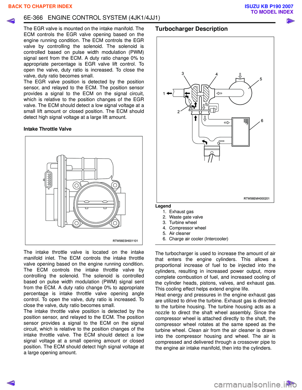
a large opening amount.Turbocharger Description
Legend
1. Exhaust gas
2. Waste gate valve
3. Turbine wheel
4. Compressor wheel
5. Air cleaner
6. Charge air cooler (Intercooler)
The turbocharger is used to increase the amount of air
that enters the engine cylinders. This allows a
proportional increase of fuel to be injected into the
cylinders, resulting in increased power output, more
complete combustion of fuel, and increased cooling of
the cylinder heads, pistons, valves, and exhaust gas.
This cooling effect helps extend engine life.
Heat energy and pressures in the engine exhaust gas
are utilized to drive the turbine. Exhaust gas is directed
to the turbine housing. The turbine housing acts as a
nozzle to direct the shaft wheel assembly. Since the
compressor wheel is attached directly to the shaft, the
compressor wheel rotates at the same speed as the
turbine wheel. Clean air from the air cleaner is drawn
into the compressor housing and wheel. The air is
compressed and delivered through a crossover pipe to
the engine air intake manifold, then into the cylinders.
RTW56ESH001101
RTW56EMH000201
1 3
2 4
5
6
BACK TO CHAPTER INDEX
TO MODEL INDEX
ISUZU KB P190 2007
Page 2132 of 6020
6C-14 ENGINE FUEL (C24SE)
Removal
CAUTION: When repair to the fuel system has been
completed, start engine and check the fuel system
for loose connection or leakage. For the fuel system
diagnosis, see Section “Driveability and Emission".
1. Disconnect battery ground cable.
2. Loosen slowly the fuel filler cap.
NOTE: To prevent spouting out fuel to change the
pressure in the fuel tank.
NOTE: Cover opening of the filler neck to prevent an
y
dust entering.
3. Jack up the vehicle.
4. Support underneath of the fuel tank with a lifter.
5. Remove the inner liner of the wheel house on rea
r
left side.
6. Remove fasten bolt to the filler neck from the body.
7. Disconnect the quick connector (8) into the fuel
tube from the fuel pipe and the evapo tube from
evapo joint connector.
NOTE: Cover the quick connector to prevent any dust
entering and fuel leaking.
NOTE: Refer to “Fuel Tube/Quick Connector Fittings” in
this section when performing any repairs.
8. Remove fasten bolt (1) to the tank band and the tank band (2).
9. Disconnect the pump and sender connector on the
fuel pump and remove the harness from weld clip
on the fuel tank.
10. Lower the fuel tank (6).
NOTE: W hen the fuel tank is lowered from the vehicle,
don’t scratch each hose and tube by around other pars.
Installation
1. Rise the fuel tank into position.
NOTE: Ensure hoses and tubes do not foul on othe
r
component. 2. Connect the pump and sender connector to the
fuel pump and install harness to into the plastic clip
welded to the top of the fuel tank..
NOTE: The connector must be certainly connected
against stopper.
Ensure tank band anchor mates with guide hole on
frame.
3. Install the tank band to fasten bolt.
Torque: 68 N ⋅
⋅⋅
⋅
m (6.9kg ⋅
⋅⋅
⋅
m/50 lb ft)
NOTE: The anchor of the tank band must be certainl
y
installed to guide hole on frame. 4. Connect the quick connector from the fuel tube to
the fuel pipe and the evapo tube from evapo joint
connector.
NOTE: Pull off the left checker into the fuel pipe.
NOTE: Refer to “Fuel Tube/Quick Connector Fittings” in
this section when performing any repairs.
5. Install the filler neck to the body by bolt.
6. Install the inner liner of the wheel house on rea
r
side.
7. Remove lifter to support underneath of the fuel tank.
8. Put back the vehicle.
9. Tigten the filler cap until at least three clicks are
heard.
10. Connect the battery ground cable.
BACK TO CHAPTER INDEX
TO MODEL INDEX
ISUZU KB P190 2007