Page 4745 of 6020
7B1-26 Manual Transmission (MUX)
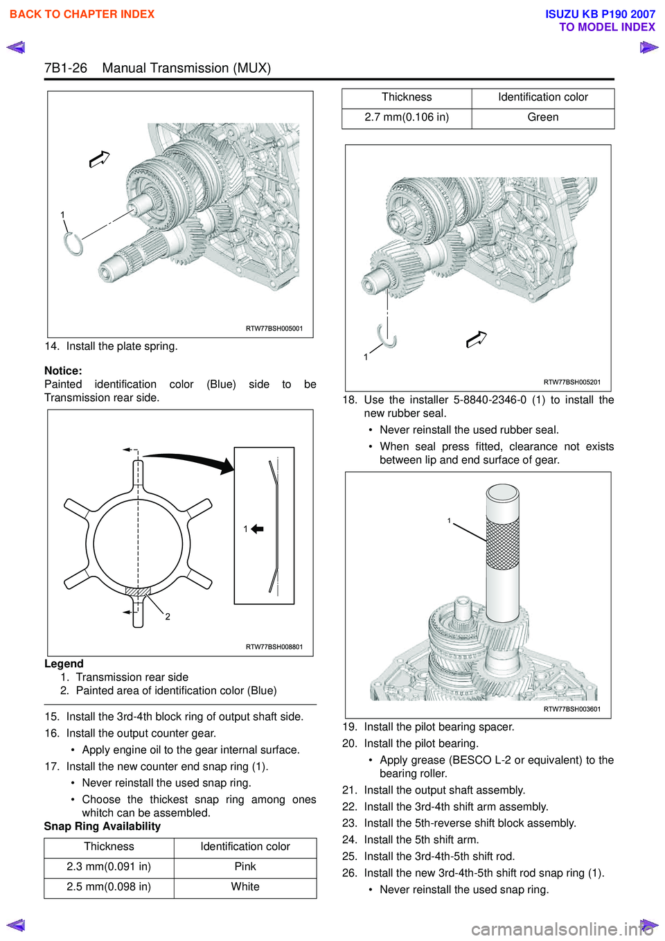
14. Install the plate spring.
Notice:
Painted identification color (Blue) side to be
Transmission rear side.
Legend 1. Transmission rear side
2. Painted area of identification color (Blue)
15. Install the 3rd-4th block ring of output shaft side.
16. Install the output counter gear.
• Apply engine oil to the gear internal surface.
17. Install the new counter end snap ring (1). • Never reinstall the used snap ring.
• Choose the thickest snap ring among ones whitch can be assembled.
Snap Ring Availability 18. Use the installer 5-8840-2346-0 (1) to install the
new rubber seal.
• Never reinstall the used rubber seal.
• When seal press fitted, clearance not exists between lip and end surface of gear.
19. Install the pilot bearing spacer.
20. Install the pilot bearing. • Apply grease (BESCO L-2 or equivalent) to thebearing roller.
21. Install the output shaft assembly.
22. Install the 3rd-4th shift arm assembly.
23. Install the 5th-reverse shift block assembly.
24. Install the 5th shift arm.
25. Install the 3rd-4th-5th shift rod.
26. Install the new 3rd-4th-5th shift rod snap ring (1).
• Never reinstall the used snap ring.
Thickness
Identification color
2.3 mm(0.091 in) Pink
2.5 mm(0.098 in) White
RTW77BSH005001
1
RTW77BSH008801
1
2
2.7 mm(0.106 in) Green
Thickness
Identification color
RTW77BSH005201
1
RTW77BSH003601
1
BACK TO CHAPTER INDEX
TO MODEL INDEX
ISUZU KB P190 2007
Page 4751 of 6020
7B1-32 Manual Transmission (MUX)
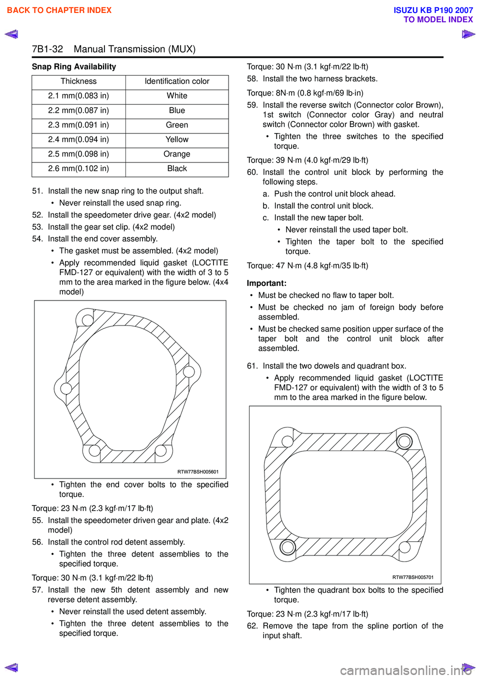
Snap Ring Availability51. Install the new snap ring to the output shaft. • Never reinstall the used snap ring.
52. Install the speedometer drive gear. (4x2 model)
53. Install the gear set clip. (4x2 model)
54. Install the end cover assembly.
• The gasket must be assembled. (4x2 model)
• Apply recommended liquid gasket (LOCTITE FMD-127 or equivalent) with the width of 3 to 5
mm to the area marked in the figure below. (4x4
model)
• Tighten the end cover bolts to the specified torque.
Torque: 23 N ⋅m (2.3 kgf ⋅m/17 lb ⋅ft)
55. Install the speedometer driven gear and plate. (4x2 model)
56. Install the control rod detent assembly.
• Tighten the three detent assemblies to thespecified torque.
Torque: 30 N ⋅m (3.1 kgf ⋅m/22 lb ⋅ft)
57. Install the new 5th detent assembly and new reverse detent assembly.
• Never reinstall the used detent assembly.
• Tighten the three detent assemblies to the specified torque. Torque: 30 N
⋅m (3.1 kgf ⋅m/22 lb ⋅ft)
58. Install the two harness brackets.
Torque: 8N ⋅m (0.8 kgf ⋅m/69 lb ⋅in)
59. Install the reverse switch (Connector color Brown), 1st switch (Connector color Gray) and neutral
switch (Connector color Brown) with gasket.
• Tighten the three switches to the specified torque.
Torque: 39 N ⋅m (4.0 kgf ⋅m/29 lb ⋅ft)
60. Install the control unit block by performing the following steps.
a. Push the control unit block ahead.
b. Install the control unit block.
c. Install the new taper bolt.
• Never reinstall the used taper bolt.
• Tighten the taper bolt to the specified torque.
Torque: 47 N ⋅m (4.8 kgf ⋅m/35 lb ⋅ft)
Important: • Must be checked no flaw to taper bolt.
• Must be checked no jam of foreign body before assembled.
• Must be checked same position upper surface of the taper bolt and the control unit block after
assembled.
61. Install the two dowels and quadrant box. • Apply recommended liquid gasket (LOCTITEFMD-127 or equivalent) with the width of 3 to 5
mm to the area marked in the figure below.
• Tighten the quadrant box bolts to the specified torque.
Torque: 23 N ⋅m (2.3 kgf ⋅m/17 lb ⋅ft)
62. Remove the tape from the spline portion of the input shaft.
Thickness
Identification color
2.1 mm(0.083 in) White
2.2 mm(0.087 in) Blue
2.3 mm(0.091 in) Green
2.4 mm(0.094 in) Yellow
2.5 mm(0.098 in) Orange
2.6 mm(0.102 in) Black
RTW77BSH005601
RTW77BSH005701
BACK TO CHAPTER INDEX
TO MODEL INDEX
ISUZU KB P190 2007
Page 4866 of 6020
7D-36 TRANSFER CASE
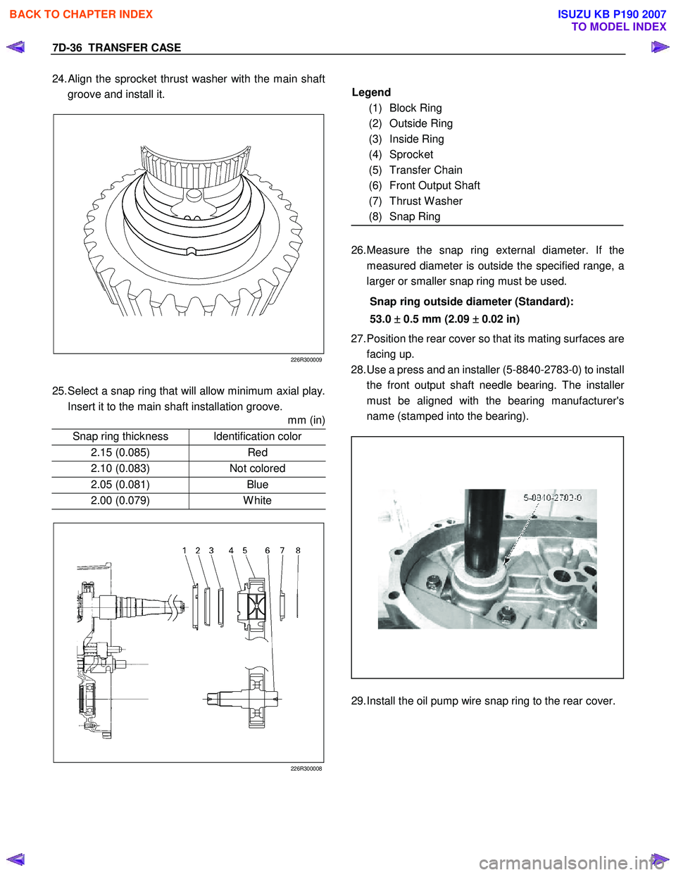
24. Align the sprocket thrust washer with the main shaft
groove and install it.
226R300009
25. Select a snap ring that will allow minimum axial play.
Insert it to the main shaft installation groove.
mm (in)
Snap ring thickness Identification color
2.15 (0.085) Red
2.10 (0.083) Not colored
2.05 (0.081) Blue
2.00 (0.079) White
226R300008
Legend
(1) Block Ring
(2) Outside Ring
(3) Inside Ring
(4) Sprocket
(5) Transfer Chain
(6) Front Output Shaft
(7) Thrust W asher
(8) Snap Ring
26. Measure the snap ring external diameter. If the
measured diameter is outside the specified range, a
larger or smaller snap ring must be used.
Snap ring outside diameter (Standard):
53.0 ±
±±
±
0.5 mm (2.09 ±
±±
±
0.02 in)
27. Position the rear cover so that its mating surfaces are
facing up.
28. Use a press and an installer (5-8840-2783-0) to install
the front output shaft needle bearing. The installe
r
must be aligned with the bearing manufacturer's
name (stamped into the bearing).
29. Install the oil pump wire snap ring to the rear cover.
BACK TO CHAPTER INDEX
TO MODEL INDEX
ISUZU KB P190 2007
Page 4915 of 6020
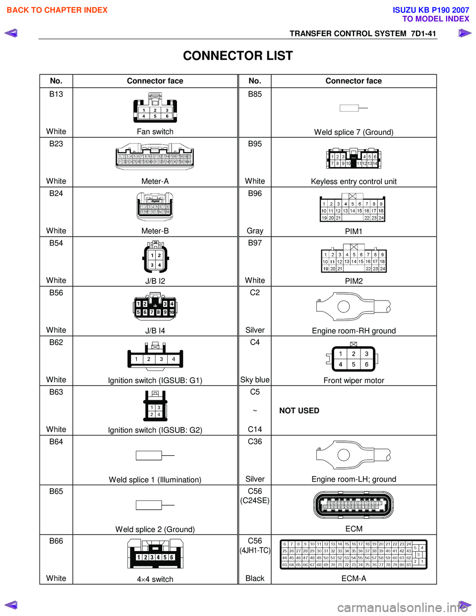
TRANSFER CONTROL SYSTEM 7D1-41
CONNECTOR LIST
No. Connector face No. Connector face
B13
White
Fan switch B85
W eld splice 7 (Ground)
B23
White
Meter-A B95
White
Keyless entry control unit
B24
White
Meter-B B96
Gray PIM1
B54
White
J/B I2 B97
WhitePIM2
B56
White
J/B I4 C2
SilverEngine room-RH ground
B62
White
Ignition switch (IGSUB: G1) C4
Sky blueFront wiper motor
B63
White
Ignition switch (IGSUB: G2) C5
~
C14 NOT USED
B64
W eld splice 1 (Illumination) C36
SilverEngine room-LH; ground
B65
W eld splice 2 (Ground) C56
(C24SE)
ECM
B66
White
4 ×4 switch C56
(4JH1-TC)
Black
ECM-A
BACK TO CHAPTER INDEX
TO MODEL INDEX
ISUZU KB P190 2007
Page 4951 of 6020
ELECTRICAL-BODY AND CHASSIS 8A-13
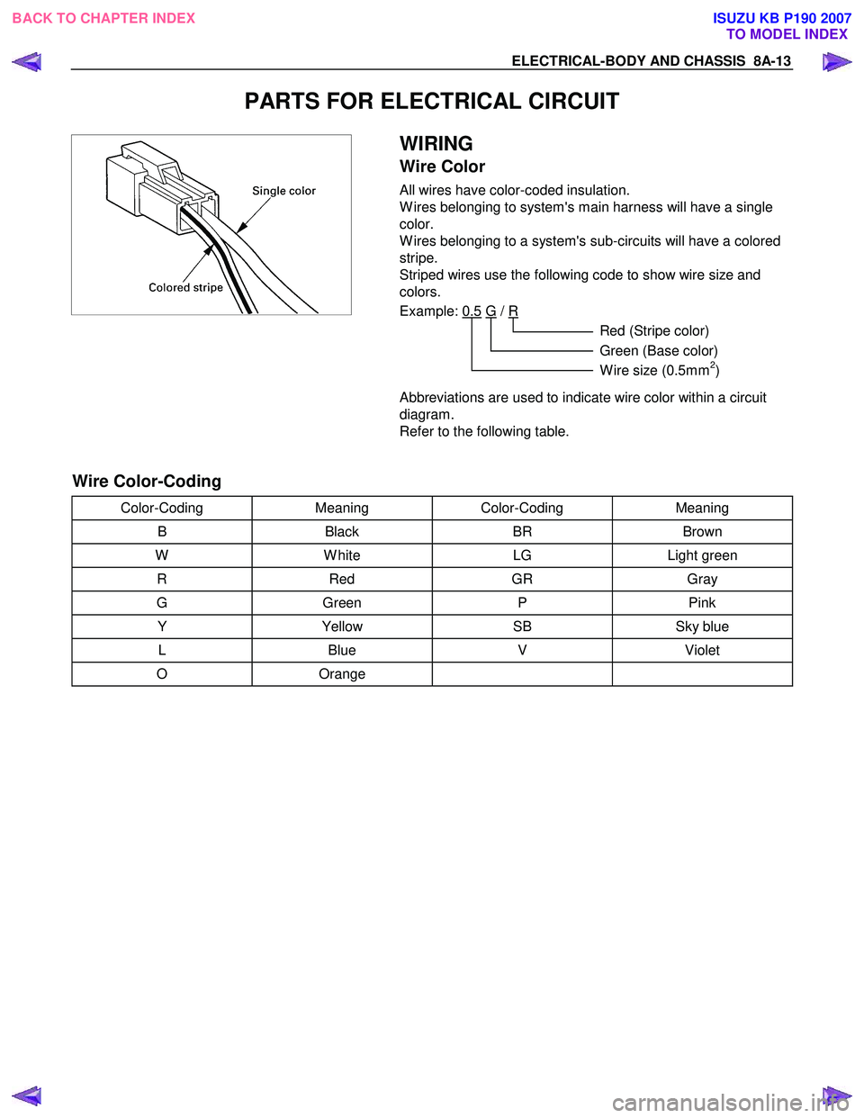
PARTS FOR ELECTRICAL CIRCUIT
WIRING
Wire Color
All wires have color-coded insulation.
W ires belonging to system's main harness will have a single
color.
W ires belonging to a system's sub-circuits will have a colored
stripe.
Striped wires use the following code to show wire size and
colors.
Example: 0.5 G
/ R
Red (Stripe color)
Green (Base color)
W ire size (0.5mm
2)
Abbreviations are used to indicate wire color within a circuit
diagram.
Refer to the following table.
Wire Color-Coding
Color-Coding Meaning Color-Coding Meaning
B Black BR Brown
W W hite LG Light green
R Red GR Gray
G Green P Pink
Y Yellow SB Sky blue
L Blue V Violet
O Orange
BACK TO CHAPTER INDEX
TO MODEL INDEXISUZU KB P190 2007
Page 4963 of 6020
ELECTRICAL-BODY AND CHASSIS 8A-25
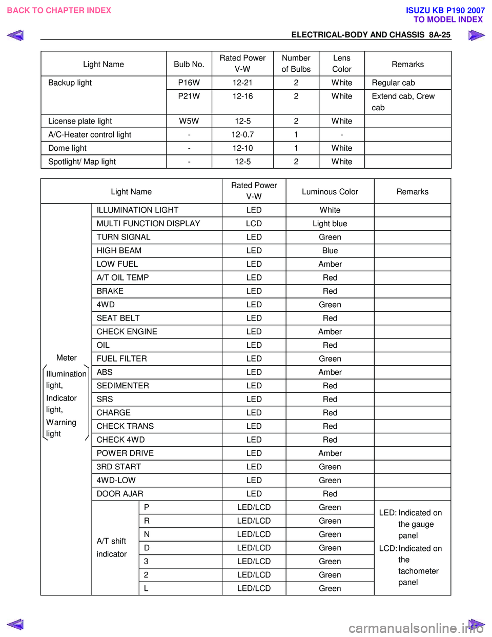
Light Name Bulb No. Rated Power
V-W Number
of Bulbs Lens
Color Remarks
P16W 12-21 2 W hite Regular cab Backup light
P21W 12-16 2 W hite Extend cab, Crew cab
License plate light W 5W 12-5 2 W hite
A/C-Heater control light - 12-0.7 1 -
Dome light - 12-10 1 W hite
Spotlight/ Map light - 12-5 2 W hite
Light Name Rated Power
V-W Luminous Color Remarks
ILLUMINATION
LIGHT LED W hite
MULTI FUNCTION DISPLAY LCD Light blue
TURN SIGNAL LED Green
HIGH BEAM LED Blue
LOW FUEL LED Amber
A/T OIL TEMP LED Red
BRAKE LED Red
4W D LED Green
SEAT BELT LED Red
CHECK ENGINE LED Amber
OIL LED Red
FUEL FILTER LED Green
ABS LED Amber
SEDIMENTER LED Red
SRS LED Red
CHARGE LED Red
CHECK TRANS LED Red
CHECK 4W D LED Red
POW ER DRIVE LED Amber
3RD START LED Green
4W D-LOW LED Green
DOOR AJAR LED Red
P LED/LCD Green
R LED/LCD Green
N LED/LCD Green
D LED/LCD Green
3 LED/LCD Green
2 LED/LCD Green
A/T shift
indicator
L LED/LCD Green LED: Indicated on
the gauge
panel
LCD: Indicated on the
tachometer
panel
Meter
Illumination
light,
Indicator
light,
W arning
light
BACK TO CHAPTER INDEX TO MODEL INDEXISUZU KB P190 2007
Page 5549 of 6020
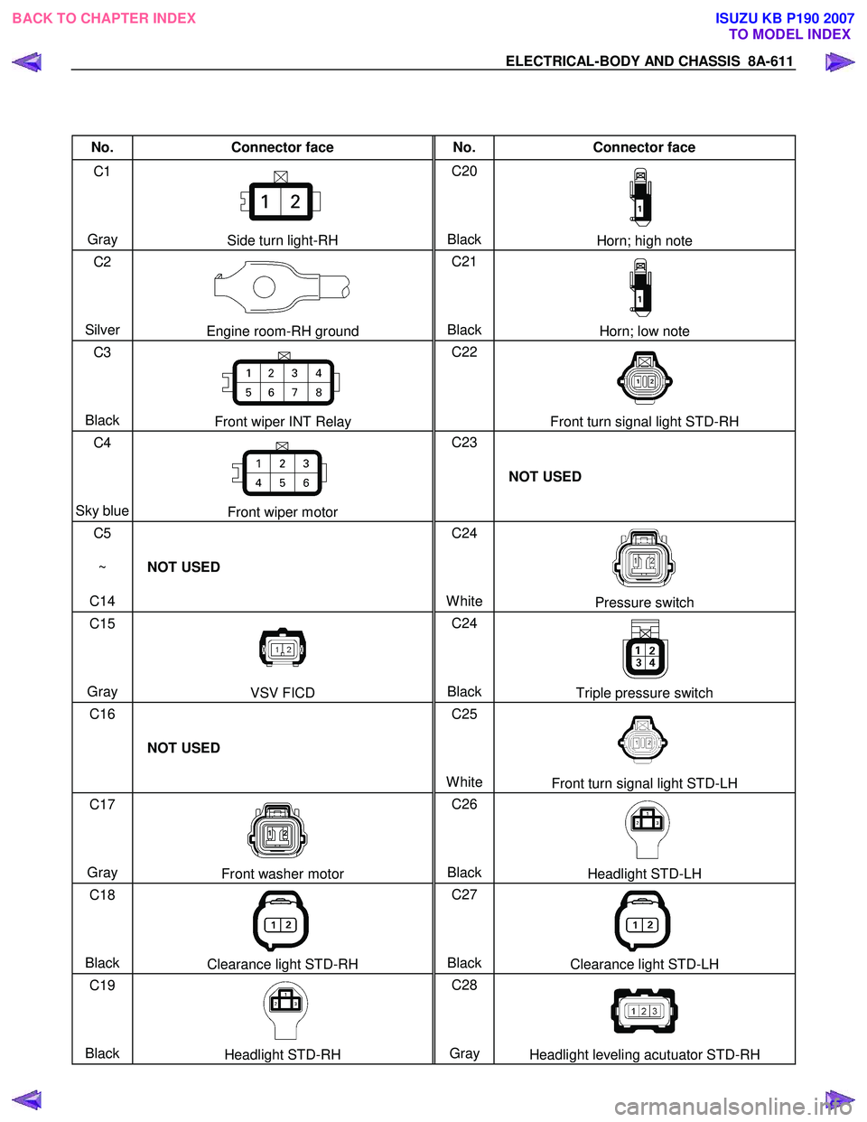
ELECTRICAL-BODY AND CHASSIS 8A-611
No. Connector face No. Connector face
C1
Gray
Side turn light-RH C20
BlackHorn; high note
C2
Silver
Engine room-RH ground C21
BlackHorn; low note
C3
Black
Front wiper INT Relay C22
Front turn signal light STD-RH
C4
Sky blue
Front wiper motor C23
NOT USED
C5
~
C14 NOT USED C24
White
Pressure switch
C15
Gray
VSV FICD C24
BlackTriple pressure switch
C16
NOT USED C25
White
Front turn signal light STD-LH
C17
Gray
Front washer motor C26
BlackHeadlight STD-LH
C18
Black
Clearance light STD-RH C27
BlackClearance light STD-LH
C19
Black
Headlight STD-RH C28
Gray Headlight leveling acutuator STD-RH
BACK TO CHAPTER INDEX TO MODEL INDEXISUZU KB P190 2007
Page 5550 of 6020
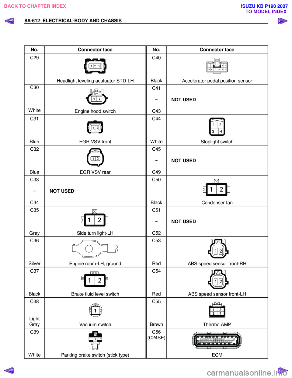
8A-612 ELECTRICAL-BODY AND CHASSIS
No. Connector face No. Connector face
C29
Headlight leveling acutuator STD-LH C40
BlackAccelerator pedal position sensor
C30
White
Engine hood switch C41
~
C43 NOT USED
C31
Blue
EGR VSV front C44
WhiteStoplight switch
C32
Blue
EGR VSV rear C45
~
C49 NOT USED
C33
~
C34 NOT USED C50
Black
Condenser fan
C35
Gray
Side turn light-LH C51
~
C52 NOT USED
C36
Silver
Engine room-LH; ground C53
Red ABS speed sensor front-RH
C37
Black
Brake fluid level switch C54
Red ABS speed sensor front-LH
C38
Light Gray
Vacuum switch C55
BrownThermo AMP
C39
White
Parking brake switch (stick type) C56
(C24SE)
ECM
BACK TO CHAPTER INDEX TO MODEL INDEXISUZU KB P190 2007