2007 ISUZU KB P190 ad blue
[x] Cancel search: ad bluePage 2176 of 6020
6E–6 ENGINE DRIVEABILITY AND EMISSIONS
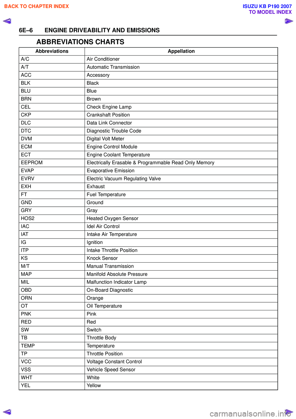
ABBREVIATIONS CHARTS
AbbreviationsAppellation
A/C Air Conditioner
A/T Automatic Transmission
ACC Accessory
BLK Black
BLU Blue
BRN Brown
CEL Check Engine Lamp
CKP Crankshaft Position
DLC Data Link Connector
DTC Diagnostic Trouble Code
DVM Digital Volt Meter
ECM Engine Control Module
ECT Engine Coolant Temperature
EEPROM Electrically Erasable & Programmable Read Only Memory
EVAP Evaporative Emission
EVRV Electric Vacuum Regulating Valve
EXH Exhaust
FT Fuel Temperature
GND Ground
GRY Gray
HOS2 Heated Oxygen Sensor
IAC Idel Air Control
IAT Intake Air Temperature
IG Ignition
ITP Intake Throttle Position
KS Knock Sensor
M/T Manual Transmission
MAP Manifold Absolute Pressure
MIL Malfunction Indicator Lamp
OBD On-Board Diagnostic
ORN Orange
OT Oil Temperature
PNK Pink
RED Red
SW Switch
TB Throttle Body
TEMP Temperature
TP Throttle Position
VCC Voltage Constant Control
VSS Vehicle Speed Sensor
WHT White
YEL Yellow
BACK TO CHAPTER INDEX
TO MODEL INDEX
ISUZU KB P190 2007
Page 2199 of 6020
ENGINE DRIVEABILITY AND EMISSIONS 6E–29
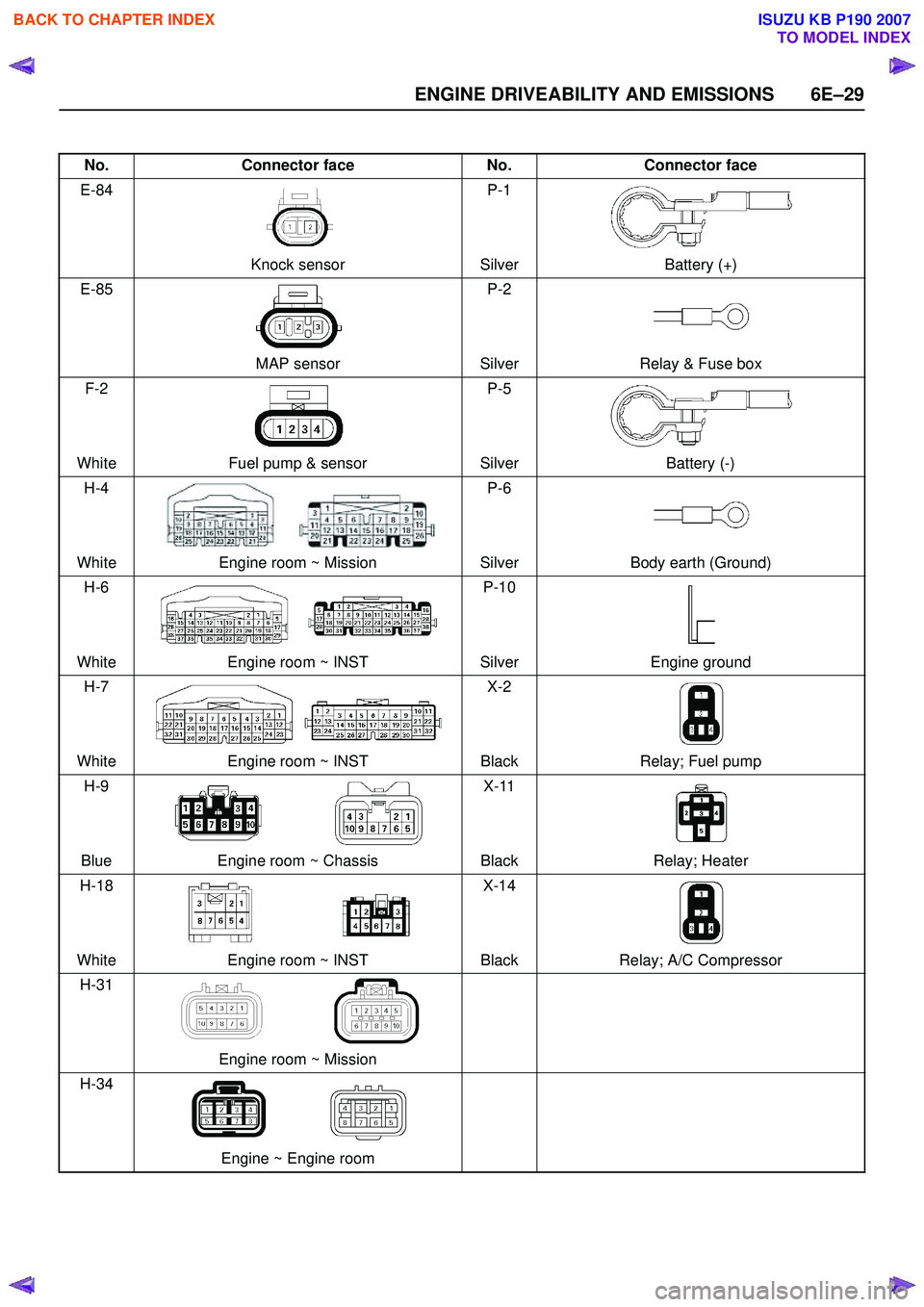
No.Connector face No.Connector face
E-84
Knock sensor P-1
Silver Battery (+)
E-85
MAP sensor P-2
Silver Relay & Fuse box
F-2
White Fuel pump & sensor P-5
Silver Battery (-)
H-4
White Engine room ~ Mission P-6
Silver Body earth (Ground)
H-6
White Engine room ~ INST P-10
Silver Engine ground
H-7
White Engine room ~ INST X-2
Black Relay; Fuel pump
H-9
Blue Engine room ~ Chassis X-11
Black Relay; Heater
H-18
White Engine room ~ INST X-14
Black Relay; A/C Compressor
H-31
Engine room ~ Mission
H-34
Engine ~ Engine room
BACK TO CHAPTER INDEX
TO MODEL INDEX
ISUZU KB P190 2007
Page 2404 of 6020
6E–234 ENGINE DRIVEABILITY AND EMISSIONS
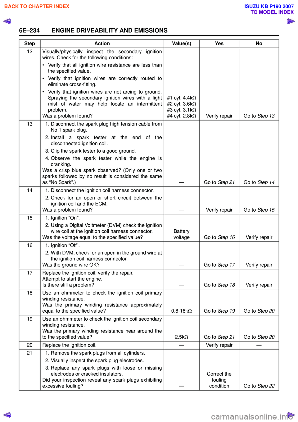
12 Visually/physically inspect the secondary ignitionwires. Check for the following conditions:
• Verify that all ignition wire resistance are less than the specified value.
• Verify that ignition wires are correctly routed to eliminate cross-fitting.
• Verify that ignition wires are not arcing to ground. Spraying the secondary ignition wires with a light
mist of water may help locate an intermittent
problem.
Was a problem found? #1 cyl. 4.4k
Ω
#2 cyl. 3.6k Ω
#3 cyl. 3.1k Ω
#4 cyl. 2.8k ΩVerify repair Go to Step 13
13 1. Disconnect the spark plug high tension cable from No.1 spark plug.
2. Install a spark tester at the end of the disconnected ignition coil.
3. Clip the spark tester to a good ground.
4. Observe the spark tester while the engine is cranking.
Was a crisp blue spark observed? (Only one or two
sparks followed by no result is considered the same
as “No Spark”.) — Go to Step 21Go to Step 14
14 1. Disconnect the ignition coil harness connector. 2. Check for an open or short circuit between theignition coil and the ECM.
Was a problem found? — Verify repair Go to Step 15
15 1. Ignition “On”. 2. Using a Digital Voltmeter (DVM) check the ignitionwire coil at the ignition coil harness connector.
Was the voltage equal to the specified value? Battery
voltage Go to Step 16Verify repair
16 1. Ignition “Off”. 2. With DVM, check for an open in the ground wire atthe ignition coil harness connector.
Was the ground wire OK? — Go to Step 17Verify repair
17 Replace the ignition coil, verify the repair. Attempt to start the engine.
Is there still a problem? — Go to Step 18Verify repair
18 Use an ohmmeter to check the ignition coil primary winding resistance.
Was the primary winding resistance approximately
equal to the specified value? 0.8-18kΩGo to Step 19 Go to Step 20
19 Use an ohmmeter to check the ignition coil secondary winding resistance.
Was the primary winding resistance hear around the
to the specified value? 2.5kΩ Go to Step 21 Go to Step 20
20 Replace the ignition coil. — Verify repair —
21 1. Remove the spark plugs from all cylinders. 2. Visually inspect the spark plug electrodes.
3. Replace any spark plugs with loose or missing electrodes or cracked insulators.
Did your inspection reveal any spark plugs exhibiting
excessive fouling? —Correct the
fouling
condition Go to Step 22
Step
Action Value(s) Yes No
BACK TO CHAPTER INDEX
TO MODEL INDEX
ISUZU KB P190 2007
Page 2651 of 6020
Engine Mechanical – V6 Page 6A1–172
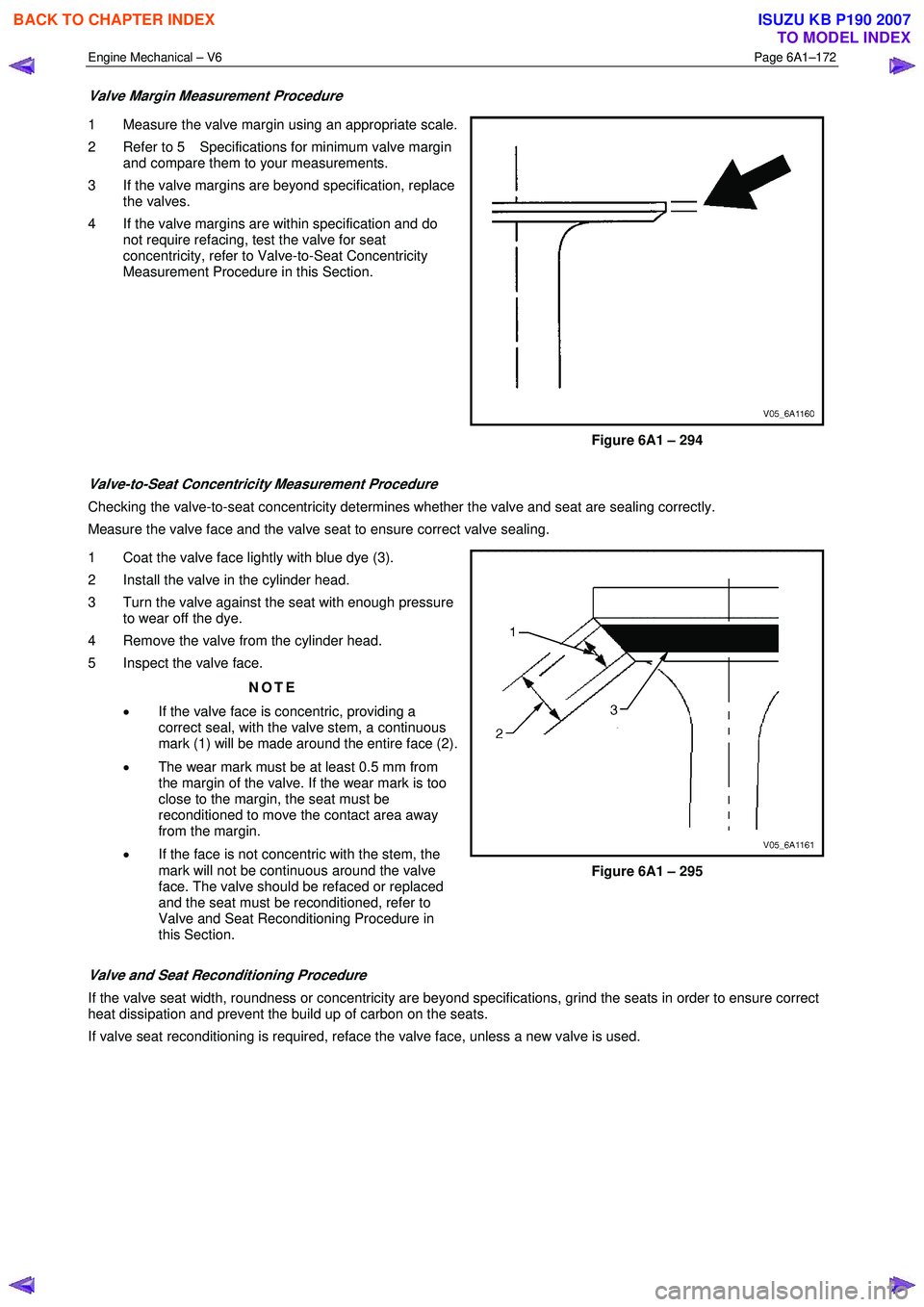
Valve Margin Measurement Procedure
1 Measure the valve margin using an appropriate scale.
2 Refer to 5 Specifications for minimum valve margin and compare them to your measurements.
3 If the valve margins are beyond specification, replace the valves.
4 If the valve margins are within specification and do not require refacing, test the valve for seat
concentricity, refer to Valve-to-Seat Concentricity
Measurement Procedure in this Section.
Figure 6A1 – 294
Valve-to-Seat Concentricity Measurement Procedure
Checking the valve-to-seat concentricity determines whether the valve and seat are sealing correctly.
Measure the valve face and the valve seat to ensure correct valve sealing.
1 Coat the valve face lightly with blue dye (3).
2 Install the valve in the cylinder head.
3 Turn the valve against the seat with enough pressure to wear off the dye.
4 Remove the valve from the cylinder head.
5 Inspect the valve face.
NOTE
• If the valve face is concentric, providing a
correct seal, with the valve stem, a continuous
mark (1) will be made around the entire face (2).
• The wear mark must be at least 0.5 mm from
the margin of the valve. If the wear mark is too
close to the margin, the seat must be
reconditioned to move the contact area away
from the margin.
• If the face is not concentric with the stem, the
mark will not be continuous around the valve
face. The valve should be refaced or replaced
and the seat must be reconditioned, refer to
Valve and Seat Reconditioning Procedure in
this Section.
Figure 6A1 – 295
Valve and Seat Reconditioning Procedure
If the valve seat width, roundness or concentricity are beyond specifications, grind the seats in order to ensure correct
heat dissipation and prevent the build up of carbon on the seats.
If valve seat reconditioning is required, reface the valve face, unless a new valve is used.
BACK TO CHAPTER INDEX
TO MODEL INDEX
ISUZU KB P190 2007
Page 3005 of 6020
Engine Mechanical – V6 Page 6A1–228
Page 6A1–228
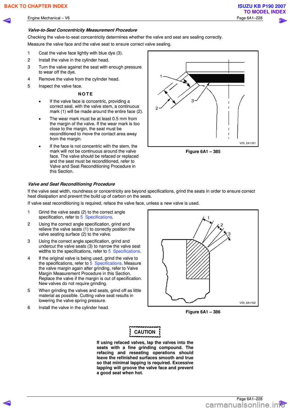
Valve-to-Seat Concentricity Measurement Procedure
Checking the valve-to-seat concentricity determines whether the valve and seat are sealing correctly.
Measure the valve face and the valve s eat to ensure correct valve sealing.
1 Coat the valve face lightly with blue dye (3).
2 Install the valve in the cylinder head.
3 Turn the valve against the seat with enough pressure to wear off the dye.
4 Remove the valve from the cylinder head.
5 Inspect the valve face.
NOTE
• If the valve face is concentric, providing a
correct seal, with the valve stem, a continuous
mark (1) will be made around the entire face (2).
• The wear mark must be at least 0.5 mm from
the margin of the valve. If the wear mark is too
close to the margin, the seat must be
reconditioned to move the contact area away
from the margin.
• If the face is not concentric with the stem, the
mark will not be continuous around the valve
face. The valve should be refaced or replaced
and the seat must be reconditioned, refer to
Valve and Seat Reconditioning Procedure in
this Section.
Figure 6A1 – 385
Valve and Seat Reconditioning Procedure
If the valve seat width, roundness or conc entricity are beyond specifications, grind the seats in order to ensure correct
heat dissipation and prevent the bu ild up of carbon on the seats.
If valve seat reconditioning is required, reface the valve face, unless a new valve is used.
1 Grind the valve seats (2) to the correct angle specification, refer to 5 Specifications.
2 Using the correct angle specification, grind and
relieve the valve seats (1) to correctly position the
valve seating surface (2) to the valve.
3 Using the correct angle specification, grind and
undercut the valve seats (3) to narrow the valve seat
widths to the specifications, refer to 5 Specifications.
4 If the original valve is being used, grind the valve to the specifications, refer to 5 Specifications. Measure
the valve margin again after grinding, refer to Valve
Margin Measurement Procedure in this Section.
Replace the valve if the margin is out of specification.
New valves do not require grinding.
5 When grinding the valves and seats, grind off as little material as possible. Cutti ng valve seat results in
lowering the valve spring pressure.
6 Install the valve in the cylinder head.
Figure 6A1 – 386
CAUTION
If using refaced valves, lap the valves into the
seats with a fine grinding compound. The
refacing and reseati ng operations should
leave the refinished surfaces smooth and true
so that minimal lapping is required. Excessive
lapping will groove the valve face and prevent
a good seat when hot.
BACK TO CHAPTER INDEX
TO MODEL INDEX
ISUZU KB P190 2007
Page 4410 of 6020
7A2-126 TRANSMISSION CONTROL SYSTEM (JR405E)
• Sticking of low & reverse brake solenoid valve
• Refer to symptom diagnosis No. A2: Vehicle Dose Not Run in R Range
6. If there is no parking. • Faulty parking pawl
• Refer to symptom diagnosis No. G1: Vehicle Moves in P Range or Parking Gear in Not
Disengaged other than P Range.
Notice: The check for the cause of abnormal noise and
vibration must be made with extreme care as it could
also be due to loss of balance in the propeller shaft,
differential, the torque converter, etc. Or insufficient
bending, rigidity, etc. in the powertrain.
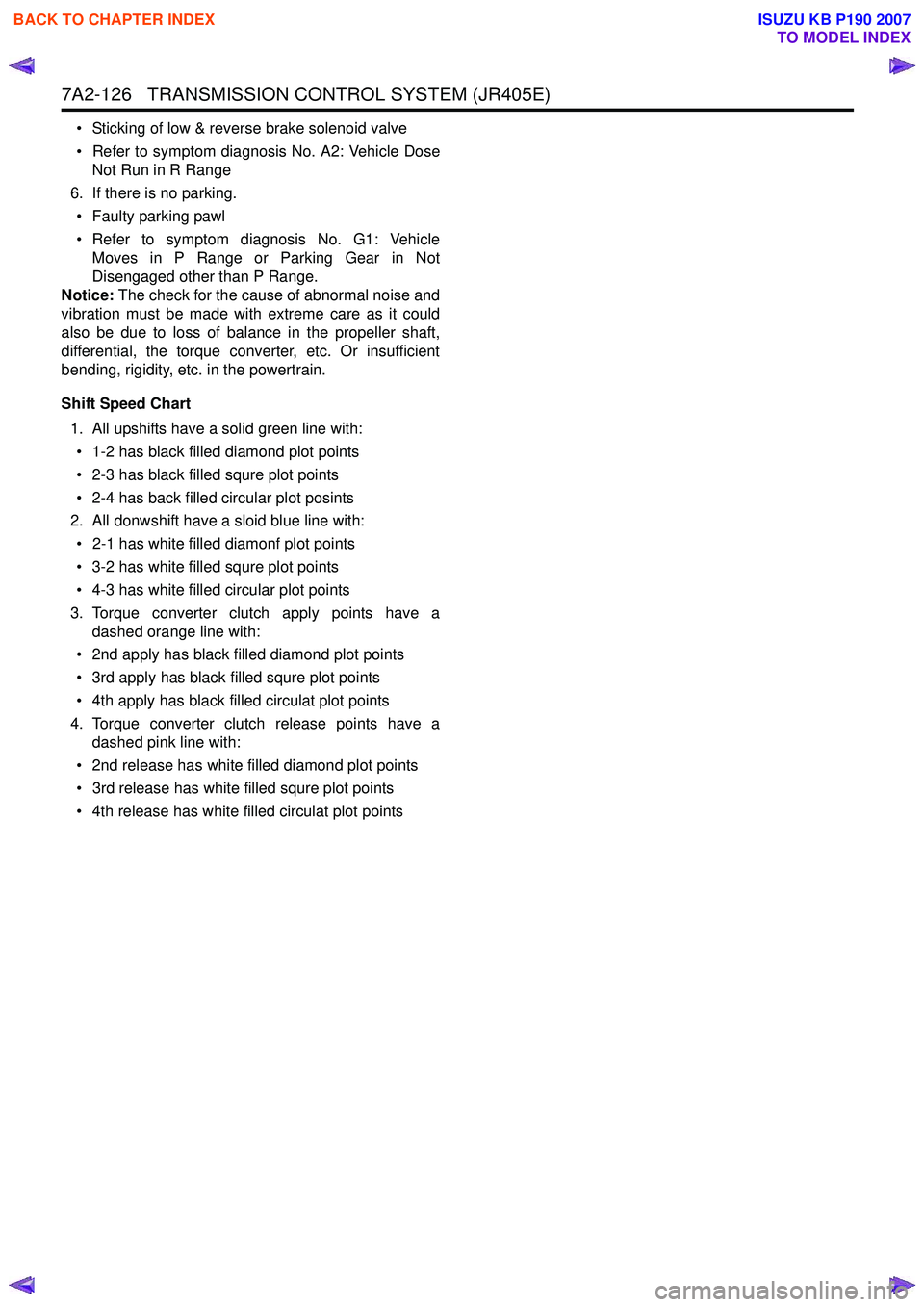
Shift Speed Chart 1. All upshifts have a solid green line with:• 1-2 has black filled diamond plot points
• 2-3 has black filled squre plot points
• 2-4 has back filled circular plot posints
2. All donwshift have a sloid blue line with:
• 2-1 has white filled diamonf plot points
• 3-2 has white filled squre plot points
• 4-3 has white filled circular plot points
3. Torque converter clutch apply points have a dashed orange line with:
• 2nd apply has black filled diamond plot points
• 3rd apply has black filled squre plot points
• 4th apply has black filled circulat plot points
4. Torque converter clutch release points have a dashed pink line with:
• 2nd release has white filled diamond plot points
• 3rd release has white filled squre plot points
• 4th release has white filled circulat plot points
BACK TO CHAPTER INDEX
TO MODEL INDEX
ISUZU KB P190 2007
Page 4470 of 6020
7A3-16 ON-VEHICLE SERVICE (JR405E)
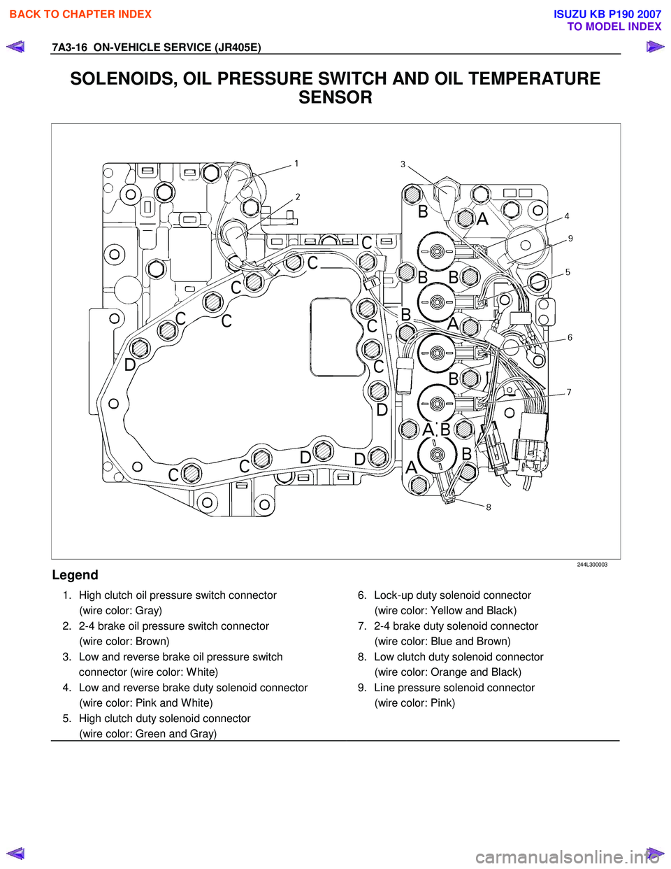
SOLENOIDS, OIL PRESSURE SWITCH AND OIL TEMPERATURE
SENSOR
244L300003
Legend
1. High clutch oil pressure switch connector
(wire color: Gray)
2. 2-4 brake oil pressure switch connector
(wire color: Brown)
3. Low and reverse brake oil pressure switch connector (wire color: W hite)
4. Low and reverse brake duty solenoid connector
(wire color: Pink and W hite)
5. High clutch duty solenoid connector
(wire color: Green and Gray)
6. Lock-up duty solenoid connector
(wire color: Yellow and Black)
7. 2-4 brake duty solenoid connector
(wire color: Blue and Brown)
8. Low clutch duty solenoid connector
(wire color: Orange and Black)
9. Line pressure solenoid connector
(wire color: Pink)
BACK TO CHAPTER INDEX
TO MODEL INDEX
ISUZU KB P190 2007
Page 4492 of 6020
UNIT REPAIR (JR405E) 7A4-15
244L300003
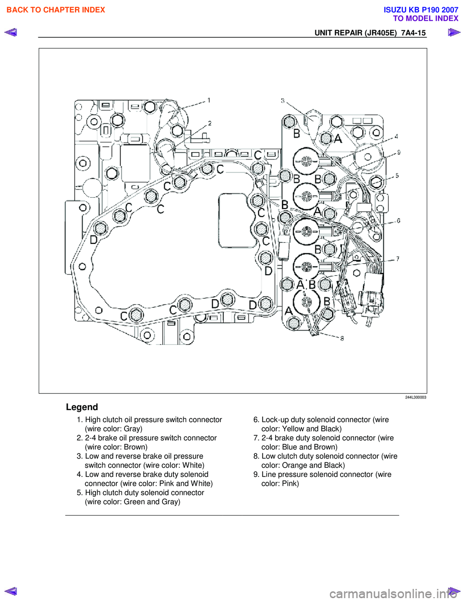
Legend
1. High clutch oil pressure switch connector (wire color: Gray)
2. 2-4 brake oil pressure switch connector (wire color: Brown)
3. Low and reverse brake oil pressure switch connector (wire color: W hite)
4. Low and reverse brake duty solenoid connector (wire color: Pink and W hite)
5. High clutch duty solenoid connector (wire color: Green and Gray)
6. Lock-up duty solenoid connector (wire
color: Yellow and Black)
7. 2-4 brake duty solenoid connector (wire color: Blue and Brown)
8. Low clutch duty solenoid connector (wire color: Orange and Black)
9. Line pressure solenoid connector (wire color: Pink)
BACK TO CHAPTER INDEX
TO MODEL INDEX
ISUZU KB P190 2007