Page 5558 of 6020
8A-620 ELECTRICAL-BODY AND CHASSIS
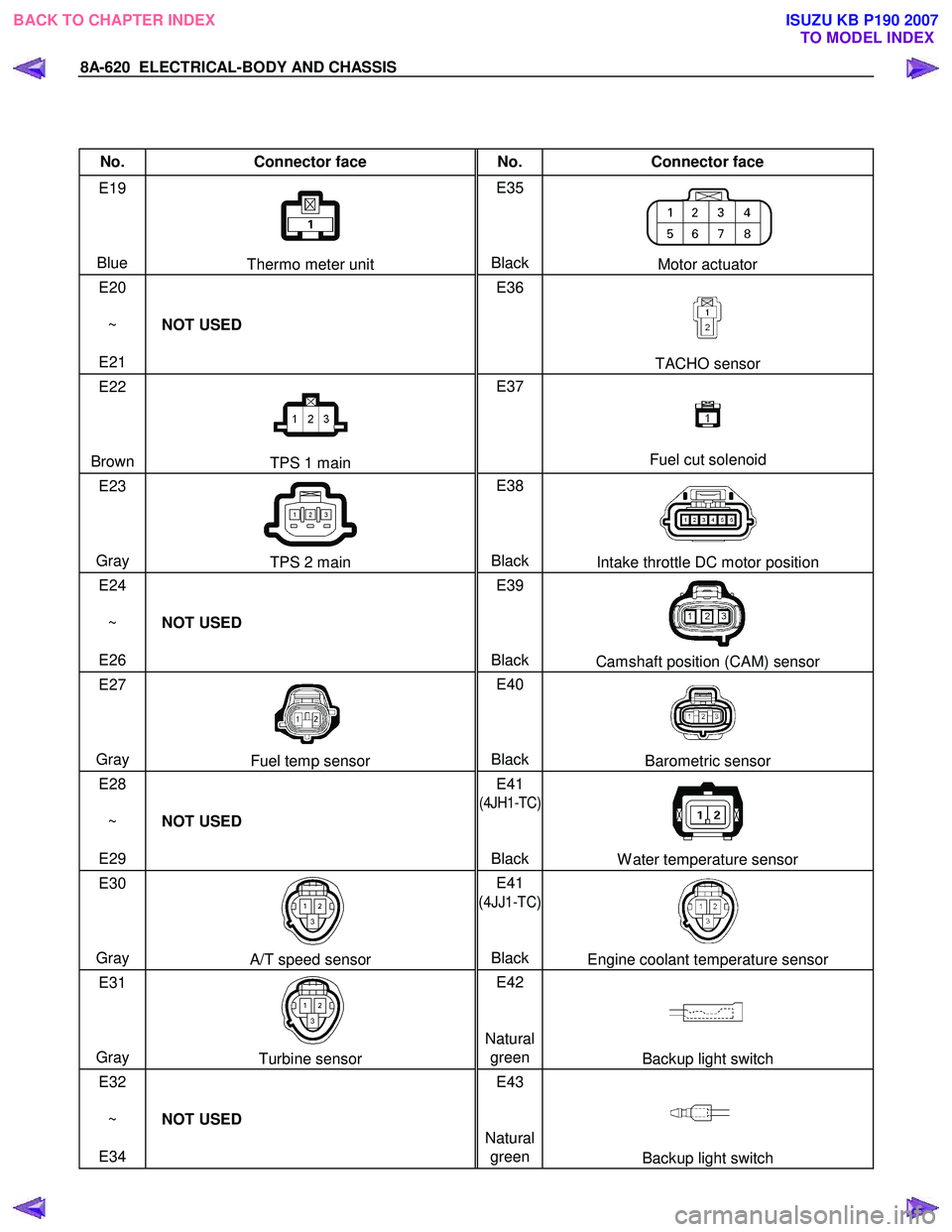
No. Connector face No. Connector face
E19
Blue
Thermo meter unit E35
BlackMotor actuator
E20
~
E21 NOT USED E36
TACHO sensor
E22
Brown
TPS 1 main E37
Fuel cut solenoid
E23
Gray
TPS 2 main E38
BlackIntake throttle DC motor position
E24
~
E26 NOT USED E39
Black
Camshaft position (CAM) sensor
E27
Gray
Fuel temp sensor E40
BlackBarometric sensor
E28
~
E29 NOT USED E41
(4JH1-TC)
Black
W ater temperature sensor
E30
Gray
A/T speed sensor E41
(
4JJ1-TC)
Black
Engine coolant temperature sensor
E31
Gray
Turbine sensor E42
Natural greenBackup light switch
E32
~
E34 NOT USED E43
Natural green
Backup light switch
BACK TO CHAPTER INDEX TO MODEL INDEXISUZU KB P190 2007
Page 5560 of 6020
8A-622 ELECTRICAL-BODY AND CHASSIS
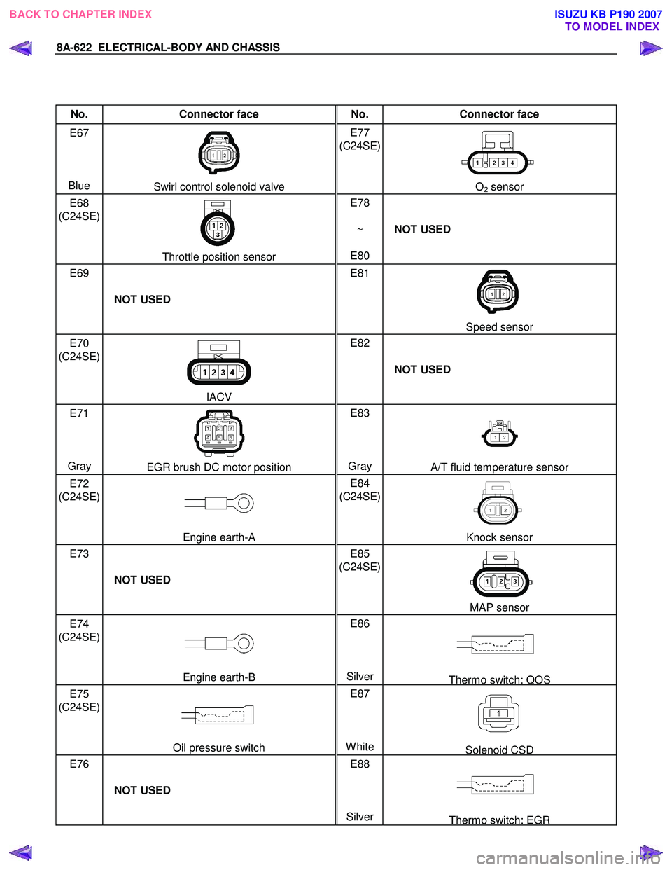
No. Connector face No. Connector face
E67
Blue
Swirl control solenoid valve E77
(C24SE)
O2 sensor
E68
(C24SE)
Throttle position sensor E78
~
E80 NOT USED
E69
NOT USED E81
Speed sensor
E70
(C24SE)
IACV E82
NOT USED
E71
Gray
EGR brush DC motor position E83
Gray A/T fluid temperature sensor
E72
(C24SE)
Engine earth-A E84
(C24SE)
Knock sensor
E73
NOT USED E85
(C24SE)
MAP sensor
E74
(C24SE)
Engine earth-B E86
SilverThermo switch; QOS
E75
(C24SE)
Oil pressure switch E87
WhiteSolenoid CSD
E76
NOT USED E88
Silver
Thermo switch; EGR
BACK TO CHAPTER INDEX TO MODEL INDEXISUZU KB P190 2007
Page 5561 of 6020
ELECTRICAL-BODY AND CHASSIS 8A-623
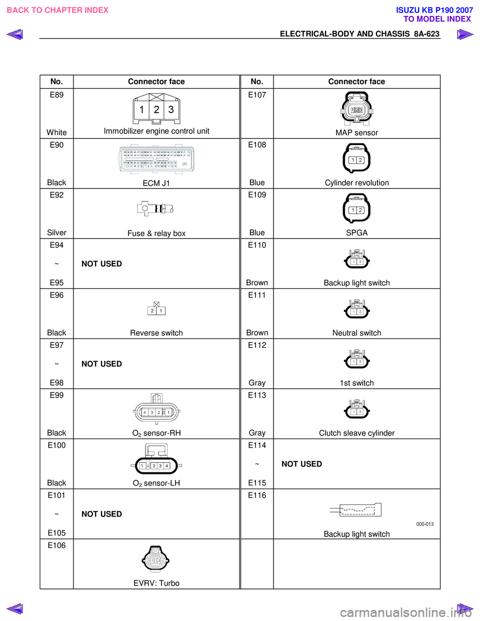
No. Connector face No. Connector face
E89
White
Immobilizer engine control unit E107
MAP sensor
E90
Black
ECM J1 E108
Blue Cylinder revolution
E92
Silver
Fuse & relay box E109
Blue SPGA
E94
~
E95 NOT USED E110
Brown
Backup light switch
E96
Black
Reverse switch E111
BrownNeutral switch
E97
~
E98 NOT USED E112
Gray
1st switch
E99
Black
O2 sensor-RH E113
Gray Clutch sleave cylinder
E100
Black
O2 sensor-LH E114
~
E115 NOT USED
E101
~
E105 NOT USED E116
Backup light switch
E106
EVRV: Turbo
BACK TO CHAPTER INDEX
TO MODEL INDEXISUZU KB P190 2007
Page 5664 of 6020
SUPPLEMENTAL RESTRAINT SYSTEM 9A-29
5. Strip 13 mm (1/2 inch) of insulation from the yellow
– green and yellow – black wire lead of the
connector.
6. Cut two 900 cm (30 feet) deployment wires from 0.8 mm
2 (18 gauge) or thicker multi–strand wire.
These wires will be used to fabricate the drive
r
deployment harness.
7. Strip 13 mm (1/2 inch) of insulation from both ends of the wires cut in the previous step.
8. Short the wires by twisting together one end from each. Deployment wires shall remain shorted and
not be connected to a power source until the ai
r
bag is to be deployed.
WARNING: FAILURE TO FOLLOW PROCEDURES
IN THE ORDER LISTED COULD RESULT IN
PERSONAL INJURY. NEVER CONNECT
DEPLOYMENT WIRES TO ANY POWER SOURCE
BEFORE CONNECTING DEPLOYMENT WIRES TO
THE AIR BAG ASSEMBLY LEADS. DEPLOYMENT
WIRES SHALL REMAIN SHORTED AND NOT BE
CONNECTED TO A POWER SOURCE UNTIL THE
AIR BAG IS TO BE DEPLOYED. THE AIR BAG
ASSEMBLY WILL IMMEDIATELY DEPLOY THE AIR
BAG WHEN A POWER SOURCE IS CONNECTED
TO IT. WEAR SAFETY GLASSES THROUGHOUT
THIS ENTIRE DEPLOYMENT AND DISPOSAL
PROCEDURE.
9. Twist together one connector wire lead to one deployment wire. The connection should be
mechanically secure.
10. Bend the twisted connection made in the previous step flat and wrap it tightly with electrical tape to
insulate and secure.
11. Twist together, bend and tape the remaining connector wire lead to the remaining deployment
wire.
12. Connect the deployment harness to the driver ai
r
bag assembly yellow connector at the base of the
steering column. Route the deployment harness
out through the driver’s side of the vehicle.
WARNING: DEPLOYMENT WIRES SHALL REMAIN
SHORTED AND NOT BE CONNECTED TO
A
POWER SOURCE UNTIL THE AIR BAG IS TO BE
DEPLOYED.
THE AIR BAG ASSEMBLY WILL IMMEDIATELY
DEPLOY THE AIR BAG WHEN A POWER SOURCE
IS CONNECTED TO IT.
Connecting the deployment wires to the powe
r
source should always be the final step in the ai
r
bag assembly deployment procedure.
Failure to follow procedures in the order listed
could result in personal injury.
13. Disconnect the passenger air bag assembly yello
w
connector located behind the glove box assembly.
14. Cut the passenger air bag assembly harness
connector from the vehicle leaving at least 15 cm
(six inches) of wire at the connector.
15. Strip 13 mm (1/2 inch) of insulation from the blue– white and pink–blue wire lead of the connector.
16. Cut two 900 cm (30 feet) deployment wires from 0.8 mm
2 (18 gauge) or thicker multi–strand wire.
These wires will be used to fabricate the
passenger deployment harness.
17. Strip 13 mm (1/2 inch) of insulation from both ends of the wires cut in the previous step.
18. Short the wires by twisting together one end from each. The deployment wires shall remain shorted
and not be connected to a power source until the
air bag is to be deployed.
WARNING: FAILURE TO FOLLOW PROCEDURES
IN THE ORDER LISTED COULD RESULT IN
PERSONAL INJURY. NEVER CONNECT
DEPLOYMENT WIRES TO ANY POWER SOURCE
BEFORE CONNECTING DEPLOYMENT WIRES TO
THE AIR BAG ASSEMBLY LEADS. DEPLOYMENT
WIRES SHALL REMAIN SHORTED AND NOT BE
CONNECTED TO A POWER SOURCE UNTIL THE
AIR BAG IS TO BE DEPLOYED. THE AIR BAG
ASSEMBLY WILL IMMEDIATELY DEPLOY THE AIR
BAG WHEN A POWER SOURCE IS CONNECTED
TO IT. WEAR SAFETY GLASSES THROUGHOUT
THIS ENTIRE DEPLOYMENT AND DISPOSAL
PROCEDURE.
19. Twist together one connector wire lead to one deployment wire. The connection should be
mechanically secure.
20. Bend the twisted connection made in the previous step flat and wrap it tightly with electrical tape to
insulate and secure.
21. Twist together, bend and tape the remaining connector wire lead to the remaining deployment
wire.
22. Connect the deployment harness to the passenge
r
air bag assembly yellow connector located behind
the glove box assembly. Route the deployment
harness out through the passenger side of the
vehicle.
WARNING: DEPLOYMENT WIRES SHALL REMAIN
SHORTED AND NOT BE CONNECTED TO
A
POWER SOURCE UNTIL THE AIR BAG IS TO BE
DEPLOYED. THE AIR BAG ASSEMBLY WILL
IMMEDIATELY DEPLOY THE AIR BAG WHEN
A
POWER SOURCE IS CONNECTED TO IT.
CONNECTING THE DEPLOYMENT WIRES
SHOULD ALWAYS BE THE FINAL STEP IN THE
AIR BAG ASSEMBLY DEPLOYMENT PROCEDURE.
FAILURE TO FOLLOW PROCEDURES IN THE
ORDER LISTED COULD RESULT IN PERSONAL
INJURY.
BACK TO CHAPTER INDEX TO MODEL INDEXISUZU KB P190 2007