2007 ISUZU KB P190 engine coolant
[x] Cancel search: engine coolantPage 3258 of 6020
Engine Management – V6 – General Information Page 6C1-1–16
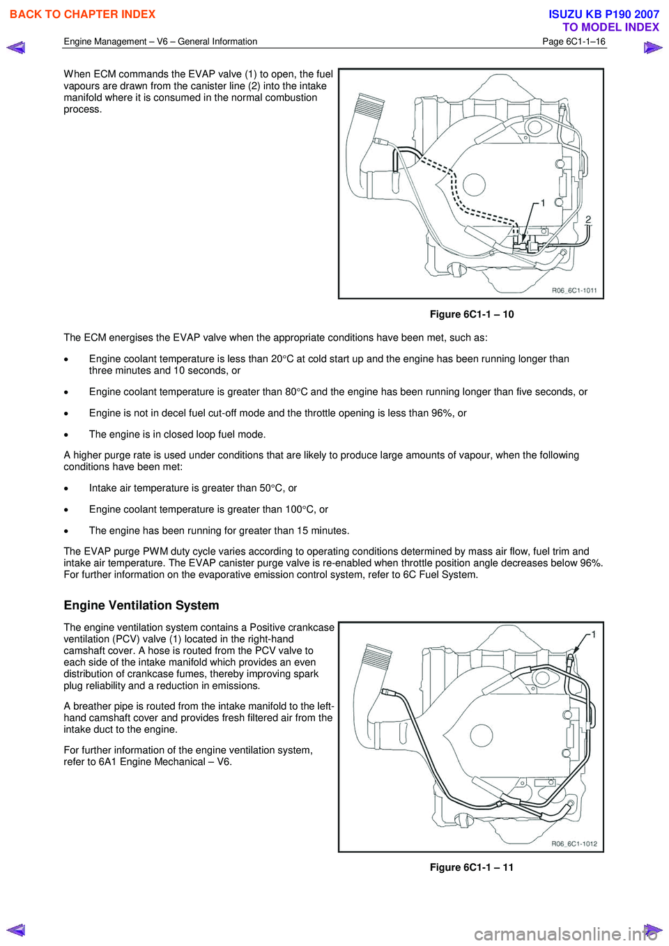
W hen ECM commands the EVAP valve (1) to open, the fuel
vapours are drawn from the canister line (2) into the intake
manifold where it is consumed in the normal combustion
process.
Figure 6C1-1 – 10
The ECM energises the EVAP valve when the appropriate conditions have been met, such as:
• Engine coolant temperature is less than 20 °C at cold start up and the engine has been running longer than
three minutes and 10 seconds, or
• Engine coolant temperature is greater than 80 °C and the engine has been running longer than five seconds, or
• Engine is not in decel fuel cut-off mode and the throttle opening is less than 96%, or
• The engine is in closed loop fuel mode.
A higher purge rate is used under conditions that are likely to produce large amounts of vapour, when the following
conditions have been met:
• Intake air temperature is greater than 50 °C, or
• Engine coolant temperature is greater than 100 °C, or
• The engine has been running for greater than 15 minutes.
The EVAP purge PW M duty cycle varies according to operating conditions determined by mass air flow, fuel trim and
intake air temperature. The EVAP canister purge valve is re-enabled when throttle position angle decreases below 96%.
For further information on the evaporative emission control system, refer to 6C Fuel System.
Engine Ventilation System
The engine ventilation system contains a Positive crankcase
ventilation (PCV) valve (1) located in the right-hand
camshaft cover. A hose is routed from the PCV valve to
each side of the intake manifold which provides an even
distribution of crankcase fumes, thereby improving spark
plug reliability and a reduction in emissions.
A breather pipe is routed from the intake manifold to the left-
hand camshaft cover and provides fresh filtered air from the
intake duct to the engine.
For further information of the engine ventilation system,
refer to 6A1 Engine Mechanical – V6.
Figure 6C1-1 – 11
BACK TO CHAPTER INDEX
TO MODEL INDEX
ISUZU KB P190 2007
Page 3265 of 6020
Engine Management – V6 – General Information Page 6C1-1–23
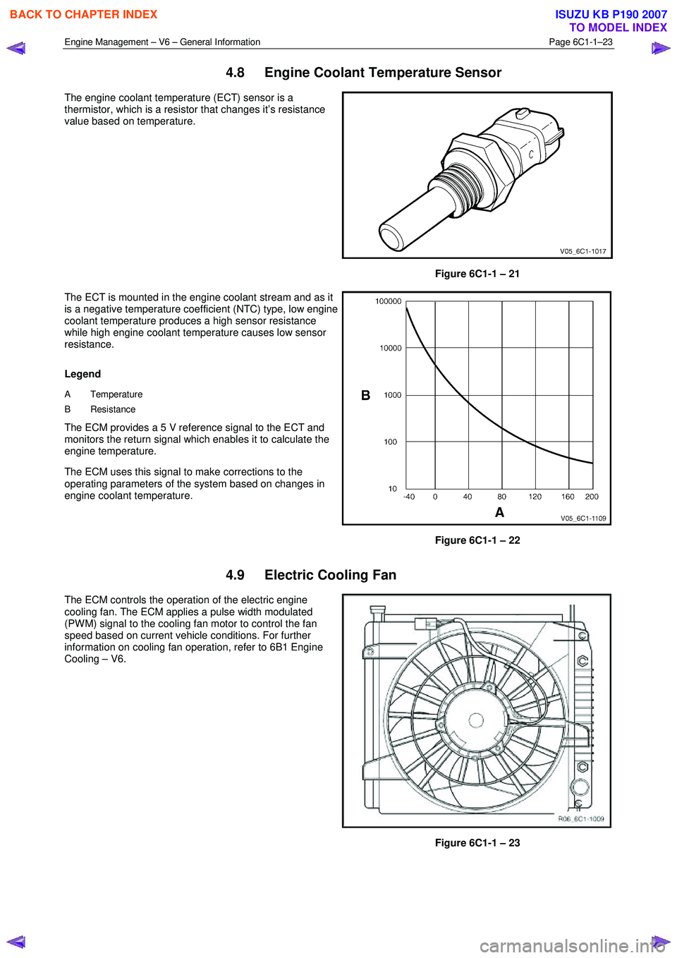
4.8 Engine Coolant Temperature Sensor
The engine coolant temperature (ECT) sensor is a
thermistor, which is a resistor that changes it’s resistance
value based on temperature.
Figure 6C1-1 – 21
The ECT is mounted in the engine coolant stream and as it
is a negative temperature coefficient (NTC) type, low engine
coolant temperature produces a high sensor resistance
while high engine coolant temperature causes low sensor
resistance.
Legend
A Temperature
B Resistance
The ECM provides a 5 V reference signal to the ECT and
monitors the return signal which enables it to calculate the
engine temperature.
The ECM uses this signal to make corrections to the
operating parameters of the system based on changes in
engine coolant temperature.
Figure 6C1-1 – 22
4.9 Electric Cooling Fan
The ECM controls the operation of the electric engine
cooling fan. The ECM applies a pulse width modulated
(PW M) signal to the cooling fan motor to control the fan
speed based on current vehicle conditions. For further
information on cooling fan operation, refer to 6B1 Engine
Cooling – V6.
Figure 6C1-1 – 23
BACK TO CHAPTER INDEX
TO MODEL INDEX
ISUZU KB P190 2007
Page 3274 of 6020
Engine Management – V6 – General Information Page 6C1-1–32
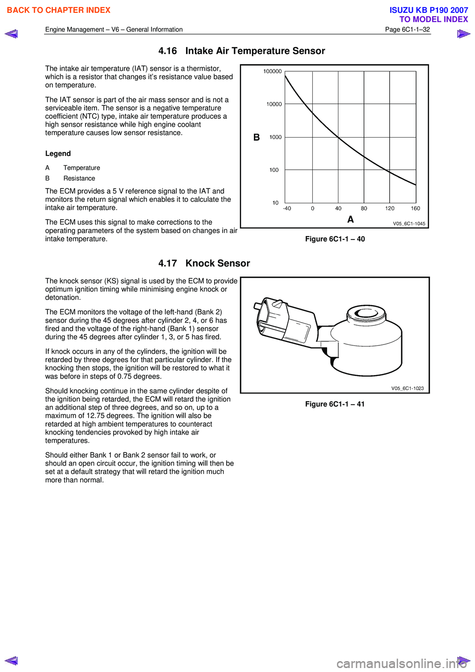
4.16 Intake Air Temperature Sensor
The intake air temperature (IAT) sensor is a thermistor,
which is a resistor that changes it’s resistance value based
on temperature.
The IAT sensor is part of the air mass sensor and is not a
serviceable item. The sensor is a negative temperature
coefficient (NTC) type, intake air temperature produces a
high sensor resistance while high engine coolant
temperature causes low sensor resistance.
Legend
A Temperature
B Resistance
The ECM provides a 5 V reference signal to the IAT and
monitors the return signal which enables it to calculate the
intake air temperature.
The ECM uses this signal to make corrections to the
operating parameters of the system based on changes in air
intake temperature.
Figure 6C1-1 – 40
4.17 Knock Sensor
The knock sensor (KS) signal is used by the ECM to provide
optimum ignition timing while minimising engine knock or
detonation.
The ECM monitors the voltage of the left-hand (Bank 2)
sensor during the 45 degrees after cylinder 2, 4, or 6 has
fired and the voltage of the right-hand (Bank 1) sensor
during the 45 degrees after cylinder 1, 3, or 5 has fired.
If knock occurs in any of the cylinders, the ignition will be
retarded by three degrees for that particular cylinder. If the
knocking then stops, the ignition will be restored to what it
was before in steps of 0.75 degrees.
Should knocking continue in the same cylinder despite of
the ignition being retarded, the ECM will retard the ignition
an additional step of three degrees, and so on, up to a
maximum of 12.75 degrees. The ignition will also be
retarded at high ambient temperatures to counteract
knocking tendencies provoked by high intake air
temperatures.
Should either Bank 1 or Bank 2 sensor fail to work, or
should an open circuit occur, the ignition timing will then be
set at a default strategy that will retard the ignition much
more than normal.
Figure 6C1-1 – 41
BACK TO CHAPTER INDEX
TO MODEL INDEX
ISUZU KB P190 2007
Page 3277 of 6020
Engine Management – V6 – General Information Page 6C1-1–35
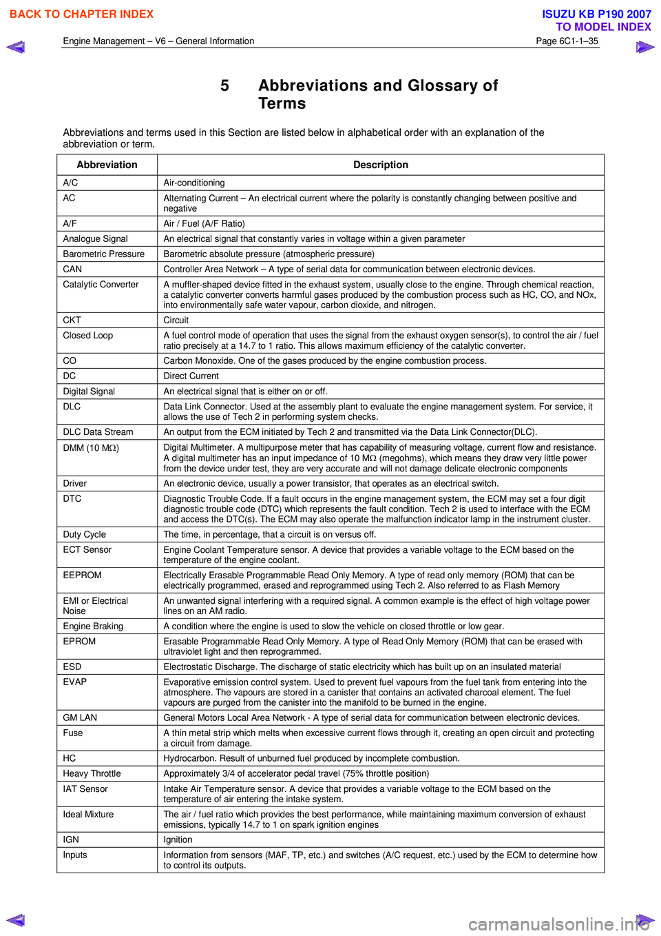
5 Abbreviations and Glossary of
Te r m s
Abbreviations and terms used in this Section are listed below in alphabetical order with an explanation of the
abbreviation or term.
Abbreviation Description
A/C Air-conditioning
AC Alternating Current – An electrical current where the polarity is constantly changing between positive and
negative
A/F Air / Fuel (A/F Ratio)
Analogue Signal An electrical signal that constantly varies in voltage within a given parameter
Barometric Pressure Barometric absolute pressure (atmospheric pressure)
CAN Controller Area Network – A type of serial data for communication between electronic devices.
Catalytic Converter
A muffler-shaped device fitted in the exhaust system, usually close to the engine. Through chemical reaction,
a catalytic converter converts harmful gases produced by the combustion process such as HC, CO, and NOx,
into environmentally safe water vapour, carbon dioxide, and nitrogen.
CKT Circuit
Closed Loop A fuel control mode of operation that uses the signal from the exhaust oxygen sensor(s), to control the air / fuel
ratio precisely at a 14.7 to 1 ratio. This allows maximum efficiency of the catalytic converter.
CO Carbon Monoxide. One of the gases produced by the engine combustion process.
DC Direct Current
Digital Signal An electrical signal that is either on or off.
DLC
Data Link Connector. Used at the assembly plant to evaluate the engine management system. For service, it
allows the use of Tech 2 in performing system checks.
DLC Data Stream An output from the ECM initiated by Tech 2 and transmitted via the Data Link Connector(DLC).
DMM (10 M Ω) Digital Multimeter. A multipurpose meter that has capability of measuring voltage, current flow and resistance.
A digital multimeter has an input impedance of 10 M Ω (megohms), which means they draw very little power
from the device under test, they are very accurate and will not damage delicate electronic components
Driver An electronic device, usually a power transistor, that operates as an electrical switch.
DTC
Diagnostic Trouble Code. If a fault occurs in the engine management system, the ECM may set a four digit
diagnostic trouble code (DTC) which represents the fault condition. Tech 2 is used to interface with the ECM
and access the DTC(s). The ECM may also operate the malfunction indicator lamp in the instrument cluster.
Duty Cycle The time, in percentage, that a circuit is on versus off.
ECT Sensor
Engine Coolant Temperature sensor. A device that provides a variable voltage to the ECM based on the
temperature of the engine coolant.
EEPROM Electrically Erasable Programmable Read Only Memory. A type of read only memory (ROM) that can be
electrically programmed, erased and reprogrammed using Tech 2. Also referred to as Flash Memory
EMI or Electrical
Noise An unwanted signal interfering with a required signal. A common example is the effect of high voltage power
lines on an AM radio.
Engine Braking A condition where the engine is used to slow the vehicle on closed throttle or low gear.
EPROM Erasable Programmable Read Only Memory. A type of Read Only Memory (ROM) that can be erased with
ultraviolet light and then reprogrammed.
ESD Electrostatic Discharge. The discharge of static electricity which has built up on an insulated material
EVAP
Evaporative emission control system. Used to prevent fuel vapours from the fuel tank from entering into the
atmosphere. The vapours are stored in a canister that contains an activated charcoal element. The fuel
vapours are purged from the canister into the manifold to be burned in the engine.
GM LAN General Motors Local Area Network - A type of serial data for communication between electronic devices.
Fuse
A thin metal strip which melts when excessive current flows through it, creating an open circuit and protecting
a circuit from damage.
HC Hydrocarbon. Result of unburned fuel produced by incomplete combustion.
Heavy Throttle Approximately 3/4 of accelerator pedal travel (75% throttle position)
IAT Sensor
Intake Air Temperature sensor. A device that provides a variable voltage to the ECM based on the
temperature of air entering the intake system.
Ideal Mixture The air / fuel ratio which provides the best performance, while maintaining maximum conversion of exhaust
emissions, typically 14.7 to 1 on spark ignition engines
IGN Ignition
Inputs Information from sensors (MAF, TP, etc.) and switches (A/C request, etc.) used by the ECM to determine how
to control its outputs.
BACK TO CHAPTER INDEX
TO MODEL INDEX
ISUZU KB P190 2007
Page 3285 of 6020
Engine Management – V6 – Diagnostics Page 6C1-2–7
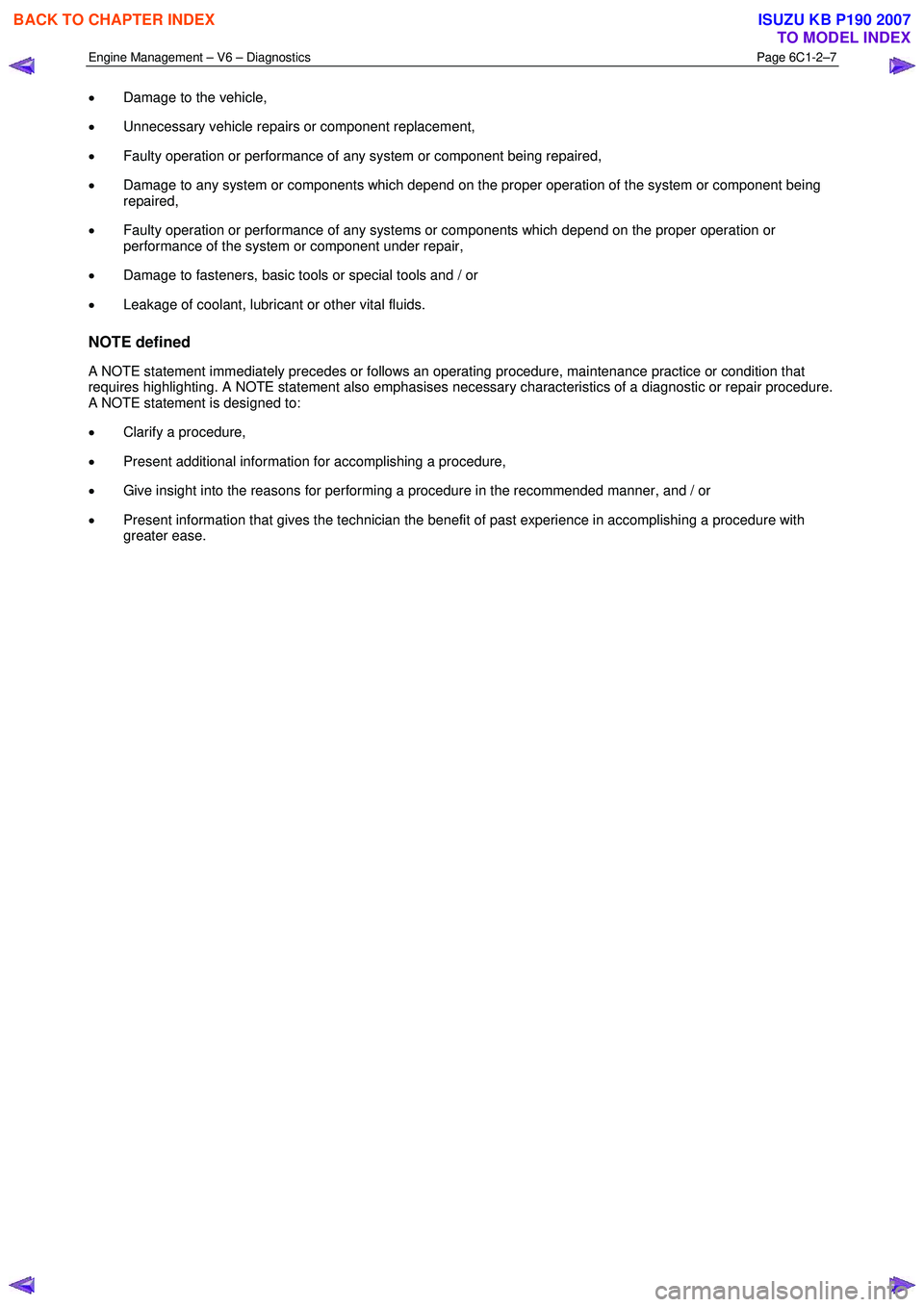
• Damage to the vehicle,
• Unnecessary vehicle repairs or component replacement,
• Faulty operation or performance of any system or component being repaired,
• Damage to any system or components which depend on the proper operation of the system or component being
repaired,
• Faulty operation or performance of any systems or components which depend on the proper operation or
performance of the system or component under repair,
• Damage to fasteners, basic tools or special tools and / or
• Leakage of coolant, lubricant or other vital fluids.
NOTE defined
A NOTE statement immediately precedes or follows an operating procedure, maintenance practice or condition that
requires highlighting. A NOTE statement also emphasises necessary characteristics of a diagnostic or repair procedure.
A NOTE statement is designed to:
• Clarify a procedure,
• Present additional information for accomplishing a procedure,
• Give insight into the reasons for performing a procedure in the recommended manner, and / or
• Present information that gives the technician the benefit of past experience in accomplishing a procedure with
greater ease.
BACK TO CHAPTER INDEX
TO MODEL INDEX
ISUZU KB P190 2007
Page 3304 of 6020
Engine Management – V6 – Diagnostics Page 6C1-2–26
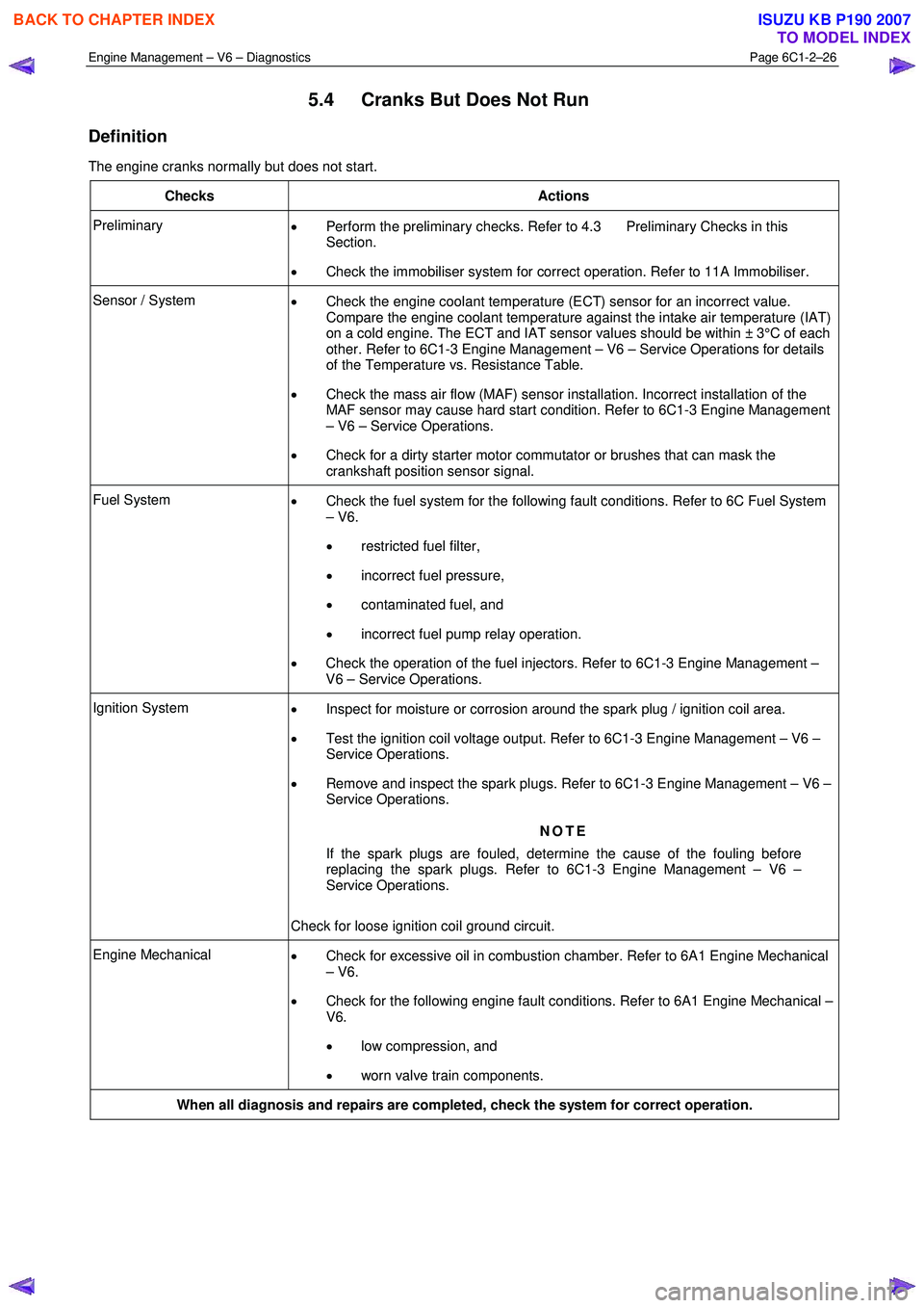
5.4 Cranks But Does Not Run
Definition
The engine cranks normally but does not start.
Checks Actions
Preliminary • Perform the preliminary checks. Refer to 4.3 Preliminary Checks in this
Section.
• Check the immobiliser system for correct operation. Refer to 11A Immobiliser.
Sensor / System
• Check the engine coolant temperature (ECT) sensor for an incorrect value.
Compare the engine coolant temperature against the intake air temperature (IAT)
on a cold engine. The ECT and IAT sensor values should be within ± 3°C of each
other. Refer to 6C1-3 Engine Management – V6 – Service Operations for details
of the Temperature vs. Resistance Table.
• Check the mass air flow (MAF) sensor installation. Incorrect installation of the
MAF sensor may cause hard start condition. Refer to 6C1-3 Engine Management
– V6 – Service Operations.
• Check for a dirty starter motor commutator or brushes that can mask the
crankshaft position sensor signal.
Fuel System • Check the fuel system for the following fault conditions. Refer to 6C Fuel System
– V6.
• restricted fuel filter,
• incorrect fuel pressure,
• contaminated fuel, and
• incorrect fuel pump relay operation.
• Check the operation of the fuel injectors. Refer to 6C1-3 Engine Management –
V6 – Service Operations.
Ignition System • Inspect for moisture or corrosion around the spark plug / ignition coil area.
• Test the ignition coil voltage output. Refer to 6C1-3 Engine Management – V6 –
Service Operations.
• Remove and inspect the spark plugs. Refer to 6C1-3 Engine Management – V6 –
Service Operations.
NOTE
If the spark plugs are fouled, determine the cause of the fouling before
replacing the spark plugs. Refer to 6C1-3 Engine Management – V6 –
Service Operations.
Check for loose ignition coil ground circuit.
Engine Mechanical • Check for excessive oil in combustion chamber. Refer to 6A1 Engine Mechanical
– V6.
• Check for the following engine fault conditions. Refer to 6A1 Engine Mechanical –
V6.
• low compression, and
• worn valve train components.
When all diagnosis and repairs are completed, check the system for correct operation.
BACK TO CHAPTER INDEX
TO MODEL INDEX
ISUZU KB P190 2007
Page 3307 of 6020
Engine Management – V6 – Diagnostics Page 6C1-2–29
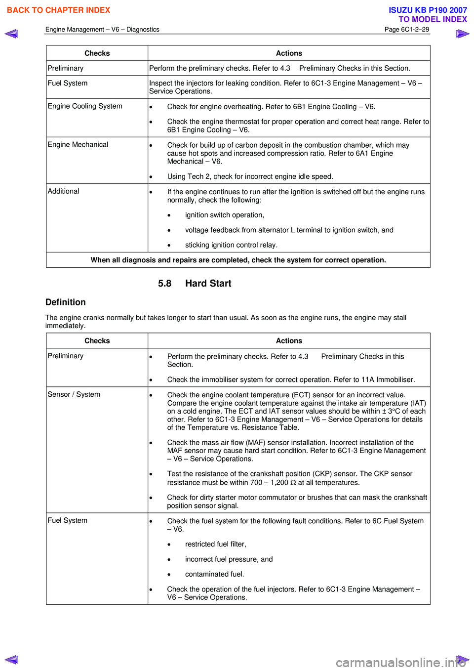
Checks Actions
Preliminary Perform the preliminary checks. Refer to 4.3 Preliminary Checks in this Section.
Fuel System Inspect the injectors for leaking condition. Refer to 6C1-3 Engine Management – V6 –
Service Operations.
Engine Cooling System • Check for engine overheating. Refer to 6B1 Engine Cooling – V6.
• Check the engine thermostat for proper operation and correct heat range. Refer to
6B1 Engine Cooling – V6.
Engine Mechanical • Check for build up of carbon deposit in the combustion chamber, which may
cause hot spots and increased compression ratio. Refer to 6A1 Engine
Mechanical – V6.
• Using Tech 2, check for incorrect engine idle speed.
Additional
• If the engine continues to run after the ignition is switched off but the engine runs
normally, check the following:
• ignition switch operation,
• voltage feedback from alternator L terminal to ignition switch, and
• sticking ignition control relay.
When all diagnosis and repairs are completed, check the system for correct operation.
5.8 Hard Start
Definition
The engine cranks normally but takes longer to start than usual. As soon as the engine runs, the engine may stall
immediately.
Checks Actions
Preliminary • Perform the preliminary checks. Refer to 4.3 Preliminary Checks in this
Section.
• Check the immobiliser system for correct operation. Refer to 11A Immobiliser.
Sensor / System
• Check the engine coolant temperature (ECT) sensor for an incorrect value.
Compare the engine coolant temperature against the intake air temperature (IAT)
on a cold engine. The ECT and IAT sensor values should be within ± 3°C of each
other. Refer to 6C1-3 Engine Management – V6 – Service Operations for details
of the Temperature vs. Resistance Table.
• Check the mass air flow (MAF) sensor installation. Incorrect installation of the
MAF sensor may cause hard start condition. Refer to 6C1-3 Engine Management
– V6 – Service Operations.
• Test the resistance of the crankshaft position (CKP) sensor. The CKP sensor
resistance must be within 700 – 1,200 Ω at all temperatures.
• Check for dirty starter motor commutator or brushes that can mask the crankshaft
position sensor signal.
Fuel System • Check the fuel system for the following fault conditions. Refer to 6C Fuel System
– V6.
• restricted fuel filter,
• incorrect fuel pressure, and
• contaminated fuel.
• Check the operation of the fuel injectors. Refer to 6C1-3 Engine Management –
V6 – Service Operations.
BACK TO CHAPTER INDEX
TO MODEL INDEX
ISUZU KB P190 2007
Page 3315 of 6020
Engine Management – V6 – Diagnostics Page 6C1-2–37
6 Functional Checks
6.1 General Information
The items detailed in the following pages are to be used when there is a customer complaint and there are no diagnostic
trouble codes set, or one or more of the Tech 2 data values are not within the typical values. They are also to be used
when instructed from a DTC table. Before using these tables, you should refer to 5 Symptoms Diagnostics in this
Section, which may direct you to using the following functional checks.
The purpose of these tables is to diagnose engine control module (ECM) controlled components or sub-systems that do
not have diagnostic trouble codes assigned to them. Another purpose of these tables is for Technicians who feel
confident that a particular part of the sub-system is not operating properly and wants only to check that particular item
for proper operation without going through lengthy diagnostic procedures.
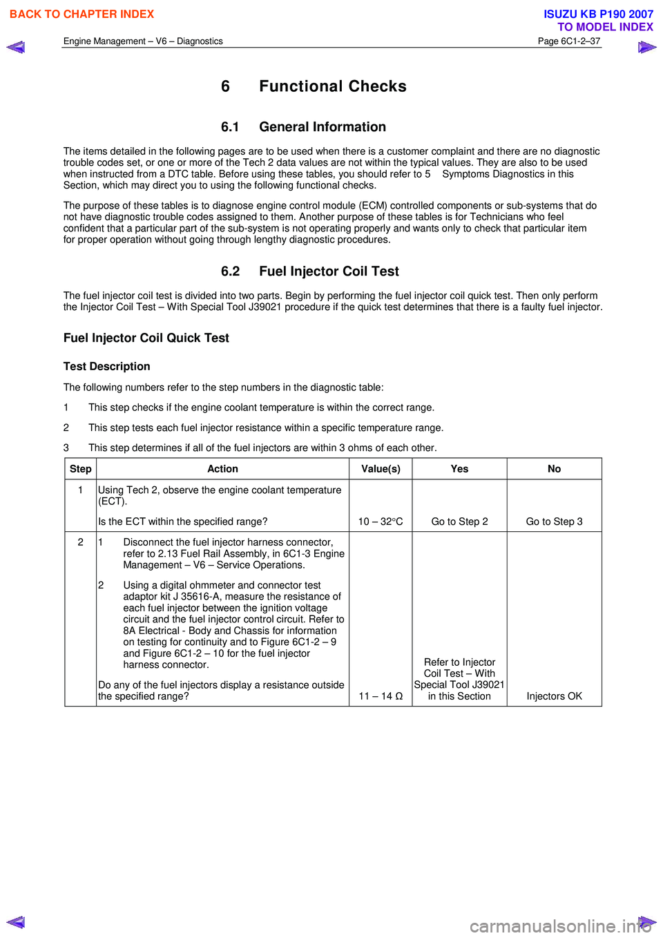
6.2 Fuel Injector Coil Test
The fuel injector coil test is divided into two parts. Begin by performing the fuel injector coil quick test. Then only perform
the Injector Coil Test – W ith Special Tool J39021 procedure if the quick test determines that there is a faulty fuel injector.
Fuel Injector Coil Quick Test
Test Description
The following numbers refer to the step numbers in the diagnostic table:
1 This step checks if the engine coolant temperature is within the correct range.
2 This step tests each fuel injector resistance within a specific temperature range.
3 This step determines if all of the fuel injectors are within 3 ohms of each other.
Step Action Value(s) Yes No
1 Using Tech 2, observe the engine coolant temperature
(ECT).
Is the ECT within the specified range? 10 – 32 °C Go to Step 2 Go to Step 3
2 1 Disconnect the fuel injector harness connector,
refer to 2.13 Fuel Rail Assembly, in 6C1-3 Engine
Management – V6 – Service Operations.
2 Using a digital ohmmeter and connector test adaptor kit J 35616-A, measure the resistance of
each fuel injector between the ignition voltage
circuit and the fuel injector control circuit. Refer to
8A Electrical - Body and Chassis for information
on testing for continuity and to Figure 6C1-2 – 9
and Figure 6C1-2 – 10 for the fuel injector
harness connector.
Do any of the fuel injectors display a resistance outside
the specified range? 11 – 14 ΩRefer to Injector
Coil Test – W ith
Special Tool J39021 in this Section Injectors OK
BACK TO CHAPTER INDEX
TO MODEL INDEX
ISUZU KB P190 2007