Page 3176 of 6020
Engine Cooling – V6 Engine Page 6B1–41
Figure 6B1 – 42 shows the drive belt routing for the HFV6 engine without air conditioning.
Figure 6B1 – 43
Legend
1 Coolant Pump
2 Generator
3 Idler 4 Power Steering
5 Crankshaft
6 Tensioner
4 Remove the drive belt from the coolant pump pulley:
a Rotate the drive belt tensioner pulley clockwise (arrow) using a 1/2” drive
extension in order to release the drive
belt tension.
b Remove the drive belt from the coolant pump pulley.
c Slowly release the drive belt tensioner.
Figure 6B1 – 44
BACK TO CHAPTER INDEX
TO MODEL INDEX
ISUZU KB P190 2007
Page 3177 of 6020
Engine Cooling – V6 Engine Page 6B1–42
5 Drain the coolant from the system. Refer to 3.3
Draining and Filling Cooling System in this
Section.
6 Remove the four coolant pump pulley attaching bolts (1), then remove the pulley (2) from the
hub (3).
Figure 6B1 – 45
7 Remove the six coolant pump attaching bolts (1) from the coolant pump (2).
Figure 6B1 – 46
8 Remove the coolant pump (1) from the engine front cover.
NOTE
If necessary, use a soft-faced hammer to
lightly tap coolant pump housing to separate it
from front cover.
9 Remove coolant pump to front cover gasket (2) and discard.
Figure 6B1 – 47
BACK TO CHAPTER INDEX
TO MODEL INDEX
ISUZU KB P190 2007
Page 3178 of 6020
Engine Cooling – V6 Engine Page 6B1–43
Inspect
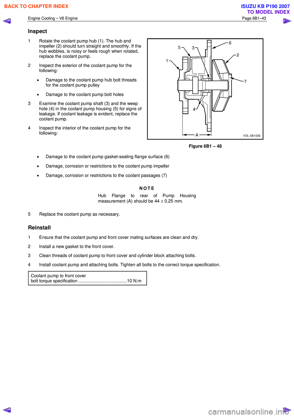
1 Rotate the coolant pump hub (1). The hub and
impeller (2) should turn straight and smoothly. If the
hub wobbles, is noisy or feels rough when rotated,
replace the coolant pump.
2 Inspect the exterior of the coolant pump for the following:
• Damage to the coolant pump hub bolt threads
for the coolant pump pulley
• Damage to the coolant pump bolt holes
3 Examine the coolant pump shaft (3) and the weep hole (4) in the coolant pump housing (5) for signs of
leakage. If coolant leakage is evident, replace the
coolant pump.
4 Inspect the interior of the coolant pump for the following:
Figure 6B1 – 48
• Damage to the coolant pump gasket-sealing flange surface (6)
• Damage, corrosion or restrictions to the coolant pump impeller
• Damage, corrosion or restrictions to the coolant passages (7)
NOTE
Hub Flange to rear of Pump Housing
measurement (A) should be 44 ± 0.25 mm.
5 Replace the coolant pump as necessary.
Reinstall
1 Ensure that the coolant pump and front cover mating surfaces are clean and dry.
2 Install a new gasket to the front cover.
3 Clean threads of coolant pump to front cover and cylinder block attaching bolts.
4 Install coolant pump and attaching bolts. Tighten all bolts to the correct torque specification.
Coolant pump to front cover
bolt torque specification .......................................10 N.m
BACK TO CHAPTER INDEX
TO MODEL INDEX
ISUZU KB P190 2007
Page 3179 of 6020
Engine Cooling – V6 Engine Page 6B1–44
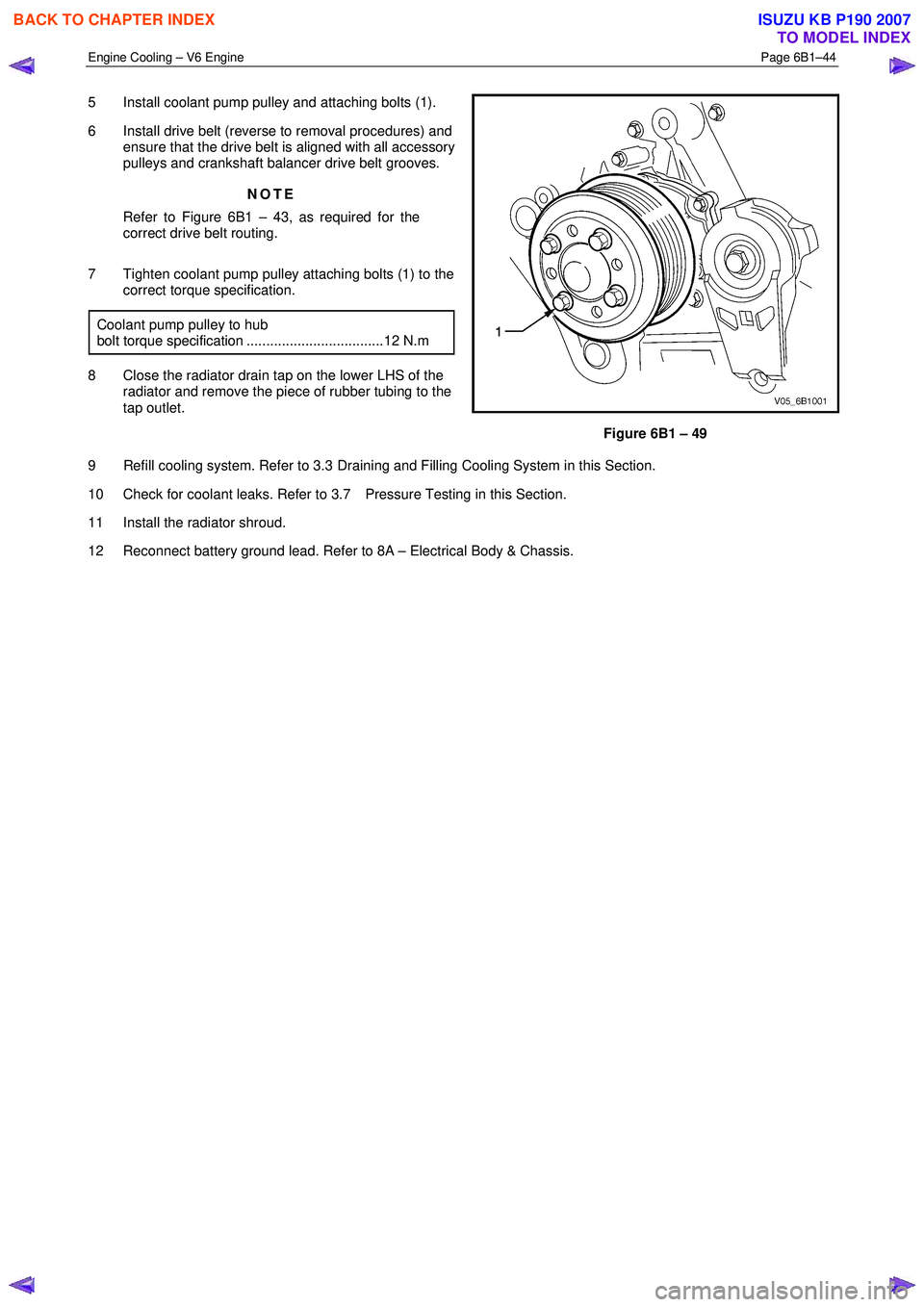
5 Install coolant pump pulley and attaching bolts (1).
6 Install drive belt (reverse to removal procedures) and ensure that the drive belt is aligned with all accessory
pulleys and crankshaft balancer drive belt grooves.
NOTE
Refer to Figure 6B1 – 43, as required for the
correct drive belt routing.
7 Tighten coolant pump pulley attaching bolts (1) to the correct torque specification.
Coolant pump pulley to hub
bolt torque specification ...................................12 N.m
8 Close the radiator drain tap on the lower LHS of the radiator and remove the piece of rubber tubing to the
tap outlet.
Figure 6B1 – 49
9 Refill cooling system. Refer to 3.3 Draining and Filling Cooling System in this Section.
10 Check for coolant leaks. Refer to 3.7 Pressure Testing in this Section.
11 Install the radiator shroud.
12 Reconnect battery ground lead. Refer to 8A – Electrical Body & Chassis.
BACK TO CHAPTER INDEX
TO MODEL INDEX
ISUZU KB P190 2007
Page 3180 of 6020
Engine Cooling – V6 Engine Page 6B1–45
3.11 Coolant Outlet Housing
Remove
Refer to 3.1 Service Notes in this Section, for
important safety items.
1 Allow engine to cool to ambient temperature (less than 50 ° C), and then remove the coolant filler cap (located at
the front left-hand side of the engine).
Disconnection of the battery affects certain
vehicle electronic systems. Refer to 1.1
WARNING, CAUTION and NOTES, before
removing the ground lead.
2 Disconnect the battery ground lead. Refer to 8A – Electrical Body & Chassis Battery.
3 Drain the coolant from the system. Refer to 3.3 Draining and Filling Cooling System.
4 Remove the complete intake manifold assembly. Refer to 6A1 Engine Mechanical.
Always wear protective safety glasses when
working with spring type hose clamps. Failure
to do so could result in eye injury.
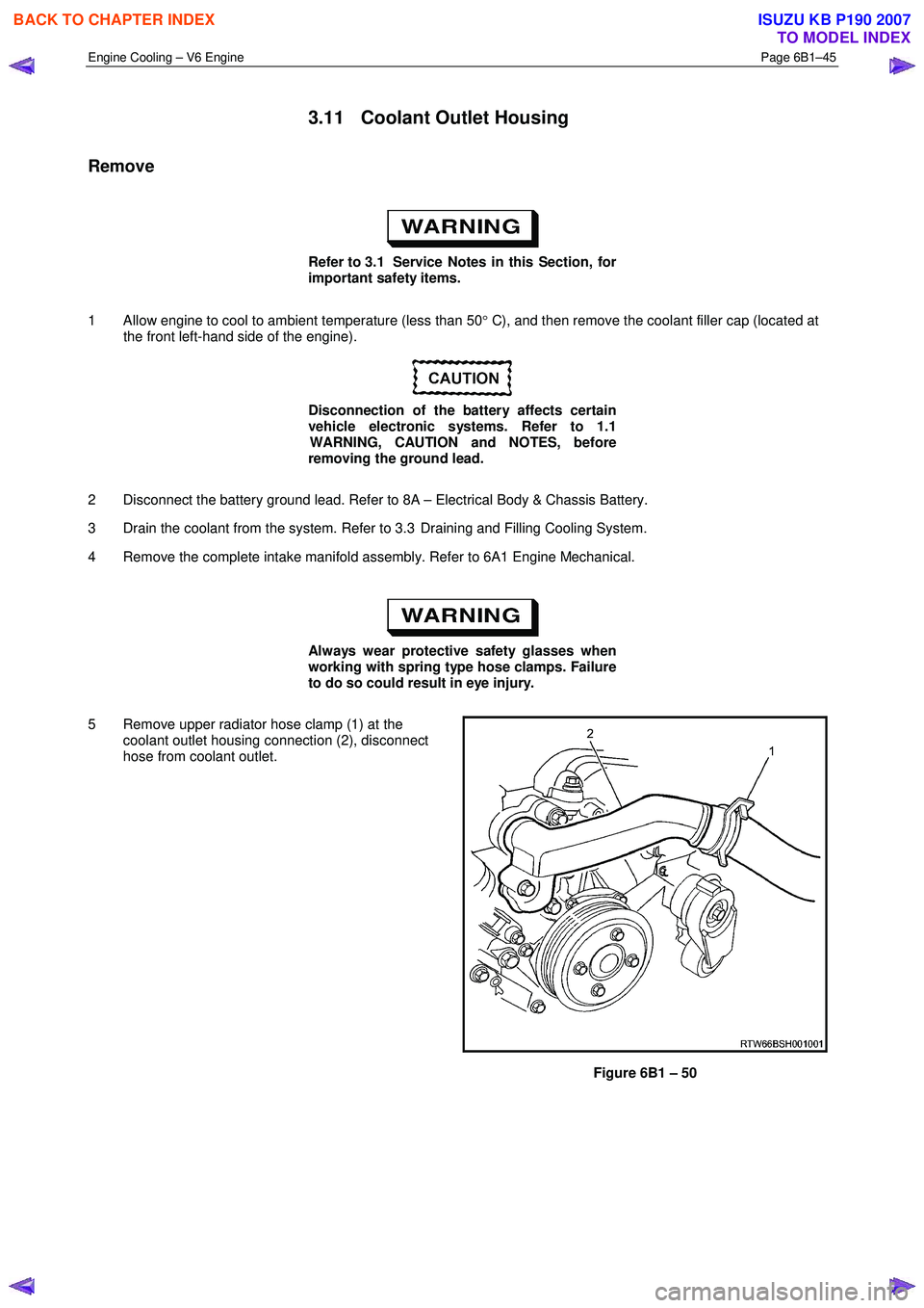
5 Remove upper radiator hose clamp (1) at the coolant outlet housing connection (2), disconnect
hose from coolant outlet.
Figure 6B1 – 50
BACK TO CHAPTER INDEX
TO MODEL INDEX
ISUZU KB P190 2007
Page 3181 of 6020

Engine Cooling – V6 Engine Page 6B1–46
6 Remove the two coolant outlet housing attaching
bolts (1), and remove coolant outlet housing (2).
7 Remove and discard coolant outlet housing O-ring (3) and seal (4).
Figure 6B1 – 51
Reinstall
1 Ensure that the coolant outlet housing and front outlet mating surfaces are clean and dry.
2 Install new O-ring and seal to coolant outlet housing.
3 Install coolant outlet housing and attaching bolts. Tighten all bolts to the correct torque specification.
Coolant outlet housing to front
outlet bolt torque specification..............................10 N.m
Always wear protective safety glasses when
working with spring type hose clamps. Failure
to do so could result in eye injury.
4 Connect the upper radiator hose and clamp to the coolant outlet housing connection.
5 Close the radiator drain tap on the lower RHS of the radiator and remove the piece of rubber tubing to the tap outlet.
6 Reinstall the intake manifold assembly. Refer to 6A1 Engine Mechanical.
7 Refill cooling system. Refer to 3.3 Draining and Filling Cooling System in this Section.
8 Check for coolant leaks. Refer to 3.7 Pressure Testing in this Section.
9 Reconnect battery ground lead. Refer to 8A – Electrical Body & Chassis.
3.12 Coolant Inlet Pipe
Remove
Refer to 3.1 Service Notes in this Section, for
important safety items.
1 Allow engine to cool to ambient temperature (less than 50 ° C), and then remove the coolant filler cap (located at
the front left-hand side of the engine).
BACK TO CHAPTER INDEX
TO MODEL INDEX
ISUZU KB P190 2007
Page 3182 of 6020
Engine Cooling – V6 Engine Page 6B1–47
Disconnection of the battery affects certain
vehicle electronic systems. Refer to 1.1
WARNING, CAUTION and NOTES, before
removing the ground lead.
2 Disconnect the battery ground lead. Refer to 8A – Electrical Body & Chassis.
Refer to ‘
‘‘
‘
Environmental Issues ’
’’
’
in 3.1
Service Notes, before draining the coolant.
3 Draining the coolant from the system. Refer to 3.3 Draining and Filling Cooling System in this Section.
4 Raise the front of the vehicle and support on safety stands. Refer to 0A General Information for the location of jacking and support points.
Always wear protective safety glasses when
working with spring type hose clamps.
Failure to do so could result in eye injury.
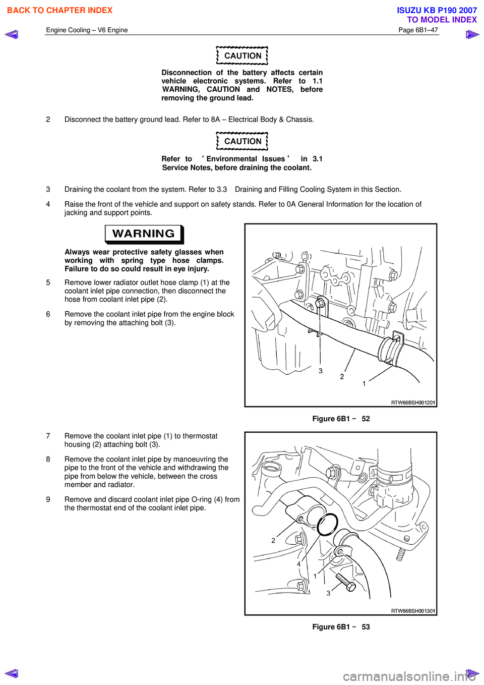
5 Remove lower radiator outlet hose clamp (1) at the coolant inlet pipe connection, then disconnect the
hose from coolant inlet pipe (2).
6 Remove the coolant inlet pipe from the engine block by removing the attaching bolt (3).
Figure 6B1 –
––
–
52
7 Remove the coolant inlet pipe (1) to thermostat housing (2) attaching bolt (3).
8 Remove the coolant inlet pipe by manoeuvring the pipe to the front of the vehicle and withdrawing the
pipe from below the vehicle, between the cross
member and radiator.
9 Remove and discard coolant inlet pipe O-ring (4) from the thermostat end of the coolant inlet pipe.
Figure 6B1 –
––
–
53
BACK TO CHAPTER INDEX
TO MODEL INDEX
ISUZU KB P190 2007
Page 3183 of 6020
Engine Cooling – V6 Engine Page 6B1–48
Install
1 Ensure that the coolant inlet pipe and thermostat housing mating surfaces are clean and dry.
2 Install new O-ring to the coolant inlet pipe.
3 Install coolant inlet pipe at the thermostat housing and secure with the attaching bolt. Tighten all bolts to the correct torque specification.
Coolant inlet pipe to thermostat
housing bolt torque specification ..........................23 N.m
4 Raise the front of the vehicle and support on safety stands. Refer to 0A General Information for the location of jacking and support points.
5 Reinstall the coolant inlet pipe to the engine block and secure with the bolt tightened to the correct torque specification.
Coolant inlet pipe to engine block bolt
torque specification .............................................25 N.m
Always wear protective safety glasses when
working with spring type hose clamps. Failure
to do so could result in eye injury.
6 Connect the lower radiator outlet hose and clamp to the coolant inlet pipe connection.
7 Close the radiator drain tap on the lower RHS of the radiator and remove the piece of rubber tubing to the tap outlet.
8 Lower the front of the vehicle.
9 Refill cooling system. Refer to 3.3 Draining and Filling Cooling System in this Section.
10 Check for coolant leaks. Refer to 3.7 Pressure Testing in this Section.
11 Reconnect battery ground lead. Refer to 8A – Electrical Body & Chassis.
3.13 Cooling Fan and Shroud Assembly
Remove
Disconnection of the battery affects certain
vehicle electronic systems. Refer to 1.1
WARNING, CAUTION and NOTES, before
removing the ground lead.
1 Disconnect the battery ground lead. Refer to 8A – Electrical Body & Chassis.
2 Remove the intake duct and mass air flow as an assembly. Refer to 6A1 Engine Mechanical.
3 Remove the coolant recovery hose from the fan shroud retaining clip.
BACK TO CHAPTER INDEX
TO MODEL INDEX
ISUZU KB P190 2007