2007 ISUZU KB P190 DTC CHECK
[x] Cancel search: DTC CHECKPage 2429 of 6020
ENGINE DRIVEABILITY AND EMISSIONS 6E–259
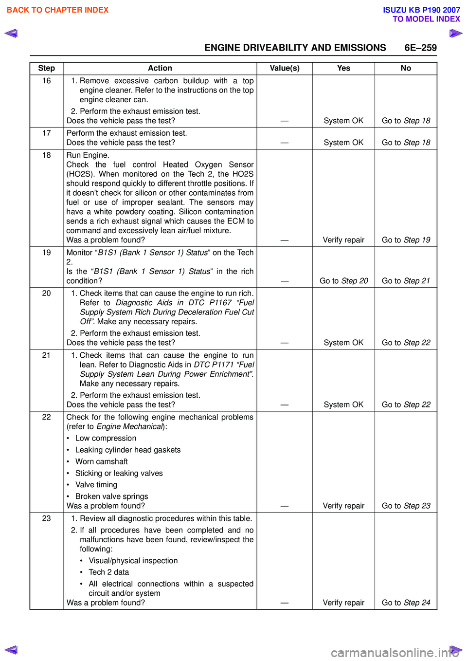
16 1. Remove excessive carbon buildup with a topengine cleaner. Refer to the instructions on the top
engine cleaner can.
2. Perform the exhaust emission test.
Does the vehicle pass the test? — System OK Go to Step 18
17 Perform the exhaust emission test. Does the vehicle pass the test? — System OK Go to Step 18
18 Run Engine. Check the fuel control Heated Oxygen Sensor
(HO2S). When monitored on the Tech 2, the HO2S
should respond quickly to different throttle positions. If
it doesn’t check for silicon or other contaminates from
fuel or use of improper sealant. The sensors may
have a white powdery coating. Silicon contamination
sends a rich exhaust signal which causes the ECM to
command and excessively lean air/fuel mixture.
Was a problem found? — Verify repair Go to Step 19
19 Monitor “ B1S1 (Bank 1 Sensor 1) Status ” on the Tech
2.
Is the “ B1S1 (Bank 1 Sensor 1) Status ” in the rich
condition? — Go to Step 20Go to Step 21
20 1. Check items that can cause the engine to run rich. Refer to Diagnostic Aids in DTC P1167 “Fuel
Supply System Rich During Deceleration Fuel Cut
Off” . Make any necessary repairs.
2. Perform the exhaust emission test.
Does the vehicle pass the test? — System OK Go to Step 22
21 1. Check items that can cause the engine to run lean. Refer to Diagnostic Aids in DTC P1171 “Fuel
Supply System Lean During Power Enrichment” .
Make any necessary repairs.
2. Perform the exhaust emission test.
Does the vehicle pass the test? — System OK Go to Step 22
22 Check for the following engine mechanical problems (refer to Engine Mechanical ):
• Low compression
• Leaking cylinder head gaskets
• Worn camshaft
• Sticking or leaking valves
• Valve timing
• Broken valve springs
Was a problem found? — Verify repair Go to Step 23
23 1. Review all diagnostic procedures within this table. 2. If all procedures have been completed and nomalfunctions have been found, review/inspect the
following:
• Visual/physical inspection
• Tech 2 data
• All electrical connections within a suspected circuit and/or system
Was a problem found? — Verify repair Go to Step 24
Step
Action Value(s) Yes No
BACK TO CHAPTER INDEX
TO MODEL INDEX
ISUZU KB P190 2007
Page 2436 of 6020

6E–266 ENGINE DRIVEABILITY AND EMISSIONS
MANIFOLD ABSOLUTE PRESSURE (MAP)
SENSOR
Location
Installed on the intake manifold.
Removal Procedure 1. Disconenct the negative battery cable.
2. Disconnect a MAP sensor connector from the MAP sensor.
3. Loosen a bolt and remove the MAP sensor from the intake manifold.
4. Remove the MAP sensor from the bracket.
Installation Procedure 1. Tighten the MAP sensor by a bolt with specified tightening torque.
Tightening Torque
• Bolt: 8N·m (0.8kgf·m) 2. Connect a MAP sensor connector to the MAP sensor.
3. Connect the negative battery cable.
NOTE: Verify any DTCs (diagnosis Trouble Code) are
not stored after replacement.
THROTTLE POSITION SENSOR (TPS)
Location
Installed on the throttle body.
Removal Procedure 1. Disconnect the negative battery cable.
2. Disconnect the TPS connector.
3. Loosen two screws and remove TPS from the throttle body.
Installation Procedure 1. Temporary tighten the TPS by two screws.
2. Connect a TPS connectors to the TPS.
3. Connect the Tech2 to the vehicle.
4. Connect the negative battery cable.
5. Select "Data Display" with the Tech2.
6. Check the throttle position data and adjust the TPS position.
7. Tighten two screws.
NOTE: Verify any DTCs (diagnosis Trouble Code) are
not stored after replacement.
BACK TO CHAPTER INDEX
TO MODEL INDEX
ISUZU KB P190 2007
Page 2445 of 6020
ENGINE DRIVEABILITY AND EMISSIONS 6E–275
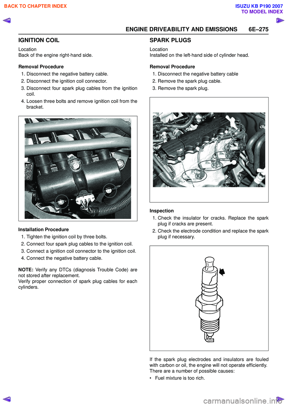
IGNITION COIL
Location
Back of the engine right-hand side.
Removal Procedure 1. Disconnect the negative battery cable.
2. Disconnect the ignition coil connector.
3. Disconnect four spark plug cables from the ignition coil.
4. Loosen three bolts and remove ignition coil from the bracket.
Installation Procedure 1. Tighten the ignition coil by three bolts.
2. Connect four spark plug cables to the ignition coil.
3. Connect a ignition coil connector to the ignition coil.
4. Connect the negative battery cable.
NOTE: Verify any DTCs (diagnosis Trouble Code) are
not stored after replacement.
Verify proper connection of spark plug cables for each
cylinders.
SPARK PLUGS
Location
Installed on the left-hand side of cylinder head.
Removal Procedure 1. Disconnect the negative battery cable
2. Remove the spark plug cable.
3. Remove the spark plug.
Inspection 1. Check the insulator for cracks. Replace the spark plug if cracks are present.
2. Check the electrode condition and replace the spark plug if necessary.
If the spark plug electrodes and insulators are fouled
with carbon or oil, the engine will not operate efficiently.
There are a number of possible causes:
• Fuel mixture is too rich.
BACK TO CHAPTER INDEX
TO MODEL INDEX
ISUZU KB P190 2007
Page 2446 of 6020
6E–276 ENGINE DRIVEABILITY AND EMISSIONS
• Oil in the combustion chamber.
• The spark plug gap is not set correctly.
If spark plug fouling is excessive, check the fuel and al
system for possible causes of trouble. If fuel and al
system are normal, install spark plugs of a higher heat
range which have the same physical dimensions as the
original equipment spark plugs.
The following symptoms are characteristics of spark
plugs that are running too hot:
• Fuel mixture is too lean.
• Heat range is incorrect.
If vehicle usage does not conform to normal driving
conditions, a more suitable spark plug may be
substituted.
If fuel and al system are normal, in most cases of this
sort, the problem can be corrected by using a colder
type spark plug with the same physical dimensions as
the original equipment spark plug.
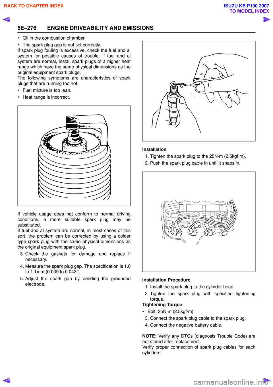
3. Check the gaskets for damage and replace if necessary.
4. Measure the spark plug gap. The specification is 1.0 to 1.1mm (0.039 to 0.043").
5. Adjust the spark gap by bending the grounded electrode. Installation
1. Tighten the spark plug to the 25N·m (2.5kgf·m).
2. Push the spark plug cable in until it snaps in.
Installation Procedure 1. Install the spark plug to the cylinder head.
2. Tighten the spark plug with specified tightening torque.
Tightening Torque
• Bolt: 25N·m (2.5kgf·m) 3. Connect the spark plug cable to the spark plug.
4. Connect the negative battery cable.
NOTE: Verify any DTCs (diagnosis Trouble Code) are
not stored after replacement.
Verify proper connection of spark plug cables for each
cylinders.
BACK TO CHAPTER INDEX
TO MODEL INDEX
ISUZU KB P190 2007
Page 2508 of 6020
Engine Mechanical – V6 Page 6A1–29
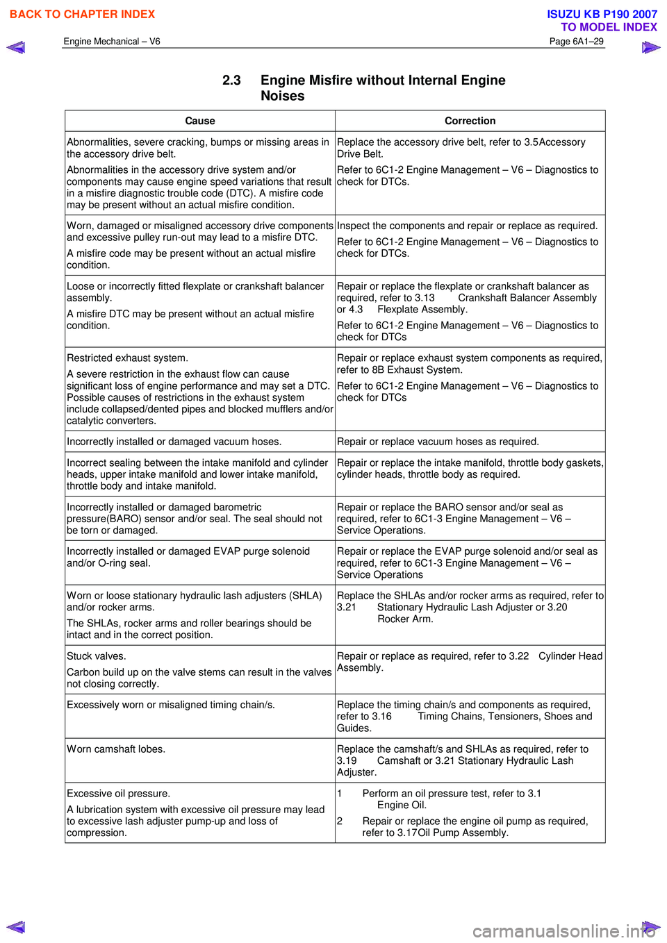
2.3 Engine Misfire without Internal Engine
Noises
Cause Correction
Abnormalities, severe cracking, bumps or missing areas in
the accessory drive belt.
Abnormalities in the accessory drive system and/or
components may cause engine speed variations that result
in a misfire diagnostic trouble code (DTC). A misfire code
may be present without an actual misfire condition. Replace the accessory drive belt, refer to 3.5
Accessory
Drive Belt.
Refer to 6C1-2 Engine Management – V6 – Diagnostics to
check for DTCs.
W orn, damaged or misaligned accessory drive components
and excessive pulley run-out may lead to a misfire DTC.
A misfire code may be present without an actual misfire
condition. Inspect the components and repair or replace as required.
Refer to 6C1-2 Engine Management – V6 – Diagnostics to
check for DTCs.
Loose or incorrectly fitted flexplate or crankshaft balancer
assembly.
A misfire DTC may be present without an actual misfire
condition. Repair or replace the flexplate or crankshaft balancer as
required, refer to 3.13 Crankshaft Balancer Assembly
or 4.3 Flexplate Assembly.
Refer to 6C1-2 Engine Management – V6 – Diagnostics to
check for DTCs
Restricted exhaust system.
A severe restriction in the exhaust flow can cause
significant loss of engine performance and may set a DTC.
Possible causes of restrictions in the exhaust system
include collapsed/dented pipes and blocked mufflers and/or
catalytic converters. Repair or replace exhaust system components as required,
refer to 8B Exhaust System.
Refer to 6C1-2 Engine Management – V6 – Diagnostics to
check for DTCs
Incorrectly installed or damaged vacuum hoses. Repair or replace vacuum hoses as required.
Incorrect sealing between the intake manifold and cylinder
heads, upper intake manifold and lower intake manifold,
throttle body and intake manifold. Repair or replace the intake manifold, throttle body gaskets,
cylinder heads, throttle body as required.
Incorrectly installed or damaged barometric
pressure(BARO) sensor and/or seal. The seal should not
be torn or damaged. Repair or replace the BARO sensor and/or seal as
required, refer to 6C1-3 Engine Management – V6 –
Service Operations.
Incorrectly installed or damaged EVAP purge solenoid
and/or O-ring seal. Repair or replace the EVAP purge solenoid and/or seal as
required, refer to 6C1-3 Engine Management – V6 –
Service Operations
W orn or loose stationary hydraulic lash adjusters (SHLA)
and/or rocker arms.
The SHLAs, rocker arms and roller bearings should be
intact and in the correct position. Replace the SHLAs and/or rocker arms as required, refer to
3.21 Stationary Hydraulic Lash Adjuster or 3.20
Rocker Arm.
Stuck valves.
Carbon build up on the valve stems can result in the valves
not closing correctly. Repair or replace as required, refer to 3.22 Cylinder Head
Assembly.
Excessively worn or misaligned timing chain/s. Replace the timing chain/s and components as required,
refer to 3.16 Timing Chains, Tensioners, Shoes and
Guides.
W orn camshaft lobes. Replace the camshaft/s and SHLAs as required, refer to
3.19 Camshaft or 3.21 Stationary Hydraulic Lash
Adjuster.
Excessive oil pressure.
A lubrication system with excessive oil pressure may lead
to excessive lash adjuster pump-up and loss of
compression. 1 Perform an oil pressure test, refer to 3.1
Engine Oil.
2 Repair or replace the engine oil pump as required, refer to 3.17 Oil Pump Assembly.
BACK TO CHAPTER INDEX
TO MODEL INDEX
ISUZU KB P190 2007
Page 2509 of 6020
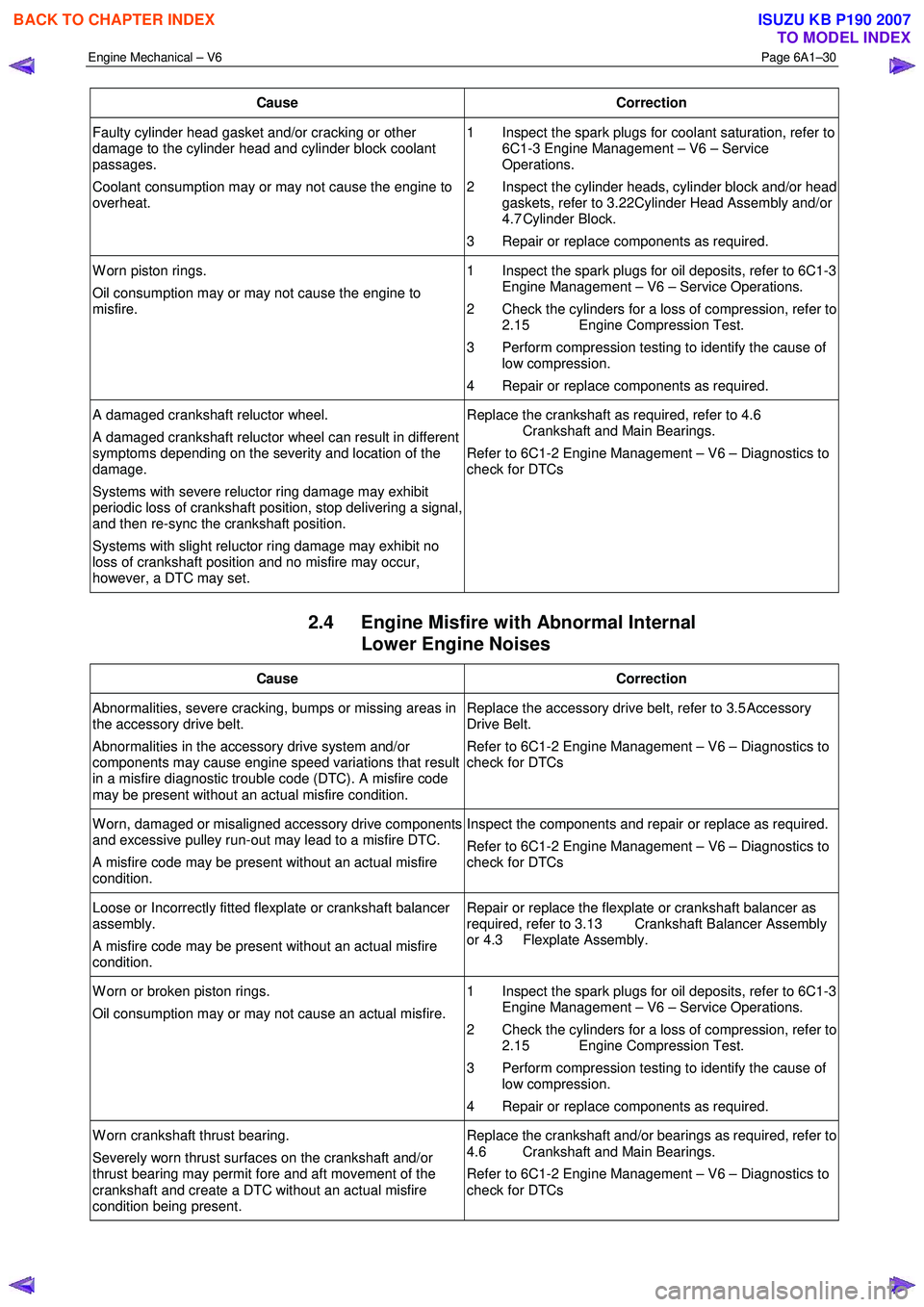
Engine Mechanical – V6 Page 6A1–30
Cause Correction
Faulty cylinder head gasket and/or cracking or other
damage to the cylinder head and cylinder block coolant
passages.
Coolant consumption may or may not cause the engine to
overheat. 1 Inspect the spark plugs for coolant saturation, refer to
6C1-3 Engine Management – V6 – Service
Operations.
2 Inspect the cylinder heads, cylinder block and/or head gaskets, refer to 3.22 Cylinder Head Assembly and/or
4.7 Cylinder Block.
3 Repair or replace components as required.
W orn piston rings.
Oil consumption may or may not cause the engine to
misfire. 1 Inspect the spark plugs for oil deposits, refer to 6C1-3
Engine Management – V6 – Service Operations.
2 Check the cylinders for a loss of compression, refer to 2.15 Engine Compression Test.
3 Perform compression testing to identify the cause of low compression.
4 Repair or replace components as required.
A damaged crankshaft reluctor wheel.
A damaged crankshaft reluctor wheel can result in different
symptoms depending on the severity and location of the
damage.
Systems with severe reluctor ring damage may exhibit
periodic loss of crankshaft position, stop delivering a signal,
and then re-sync the crankshaft position.
Systems with slight reluctor ring damage may exhibit no
loss of crankshaft position and no misfire may occur,
however, a DTC may set. Replace the crankshaft as required, refer to 4.6
Crankshaft and Main Bearings.
Refer to 6C1-2 Engine Management – V6 – Diagnostics to
check for DTCs
2.4 Engine Misfire with Abnormal Internal Lower Engine Noises
Cause Correction
Abnormalities, severe cracking, bumps or missing areas in
the accessory drive belt.
Abnormalities in the accessory drive system and/or
components may cause engine speed variations that result
in a misfire diagnostic trouble code (DTC). A misfire code
may be present without an actual misfire condition. Replace the accessory drive belt, refer to 3.5
Accessory
Drive Belt.
Refer to 6C1-2 Engine Management – V6 – Diagnostics to
check for DTCs
W orn, damaged or misaligned accessory drive components
and excessive pulley run-out may lead to a misfire DTC.
A misfire code may be present without an actual misfire
condition. Inspect the components and repair or replace as required.
Refer to 6C1-2 Engine Management – V6 – Diagnostics to
check for DTCs
Loose or Incorrectly fitted flexplate or crankshaft balancer
assembly.
A misfire code may be present without an actual misfire
condition. Repair or replace the flexplate or crankshaft balancer as
required, refer to 3.13 Crankshaft Balancer Assembly
or 4.3 Flexplate Assembly.
W orn or broken piston rings.
Oil consumption may or may not cause an actual misfire. 1 Inspect the spark plugs for oil deposits, refer to 6C1-3
Engine Management – V6 – Service Operations.
2 Check the cylinders for a loss of compression, refer to 2.15 Engine Compression Test.
3 Perform compression testing to identify the cause of low compression.
4 Repair or replace components as required.
W orn crankshaft thrust bearing.
Severely worn thrust surfaces on the crankshaft and/or
thrust bearing may permit fore and aft movement of the
crankshaft and create a DTC without an actual misfire
condition being present. Replace the crankshaft and/or bearings as required, refer to
4.6 Crankshaft and Main Bearings.
Refer to 6C1-2 Engine Management – V6 – Diagnostics to
check for DTCs
BACK TO CHAPTER INDEX
TO MODEL INDEX
ISUZU KB P190 2007
Page 2809 of 6020
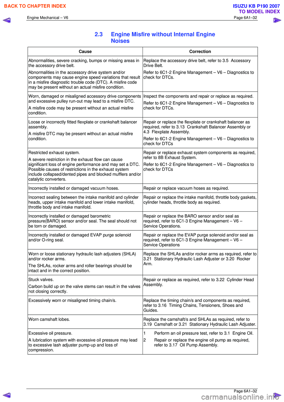
Engine Mechanical – V6 Page 6A1–32
Page 6A1–32
2.3 Engine Misfire without Internal Engine
Noises
Cause Correction
Abnormalities, severe cracking, bumps or missing areas in
the accessory drive belt.
Abnormalities in the accessory drive system and/or
components may cause engine speed variations that result
in a misfire diagnostic trouble code (DTC). A misfire code
may be present without an ac tual misfire condition. Replace the accessory drive belt, refer to 3.5 Accessory
Drive Belt.
Refer to 6C1-2 Engine Management – V6 – Diagnostics to
check for DTCs.
Worn, damaged or misaligned accessory drive components
and excessive pulley run-out may lead to a misfire DTC.
A misfire code may be present without an actual misfire
condition. Inspect the components and repair or replace as required.
Refer to 6C1-2 Engine Management – V6 – Diagnostics to
check for DTCs.
Loose or incorrectly fitted flexplate or crankshaft balancer
assembly.
A misfire DTC may be present without an actual misfire
condition. Repair or replace the flexplat
e or crankshaft balancer as
required, refer to 3.13 Crankshaft Balancer Assembly or
4.3 Flexplate Assembly.
Refer to 6C1-2 Engine Management – V6 – Diagnostics to
check for DTCs
Restricted exhaust system.
A severe restriction in the exhaust flow can cause
significant loss of engine performance and may set a DTC.
Possible causes of restrict ions in the exhaust system
include collapsed/dented pipes and blocked mufflers and/or
catalytic converters. Repair or replace exhaust syst
em components as required,
refer to 8B Exhaust System.
Refer to 6C1-2 Engine Management – V6 – Diagnostics to
check for DTCs
Incorrectly installed or damaged vacuum hoses. Repair or replace vacuum hoses as required.
Incorrect sealing between the intake manifold and cylinder
heads, upper intake manifold and lower intake manifold,
throttle body and intake manifold. Repair or replace the intake
manifold, throttle body gaskets,
cylinder heads, throttle body as required.
Incorrectly installed or damaged barometric
pressure(BARO) sensor and/or seal. The seal should not
be torn or damaged. Repair or replace the BARO sensor and/or seal as
required, refer to 6C1-3 Engine Management – V6 –
Service Operations.
Incorrectly installed or damaged EVAP purge solenoid
and/or O-ring seal. Repair or replace the EVAP purge solenoid and/or seal as
required, refer to 6C1-3 Engine Management – V6 –
Service Operations
Worn or loose stationary hydraulic lash adjusters (SHLA)
and/or rocker arms.
The SHLAs, rocker arms and roller bearings should be
intact and in the correct position. Replace the SHLAs and/or rocker arms as required, refer to
3.21 Stationary Hydraulic Las h Adjuster or 3.20 Rocker
Arm.
Stuck valves.
Carbon build up on the valve stem s can result in the valves
not closing correctly. Repair or replace as required, refer to 3.22 Cylinder Head
Assembly.
Excessively worn or misaligned timing chain/s. Replace the timing chain/s and components as required,
refer to 3.16 Timing Chains, Tensioners, Shoes and
Guides.
Worn camshaft lobes. Replace the camshaft/s and SHLAs as required, refer to
3.19 Camshaft or 3.21 Stati onary Hydraulic Lash Adjuster.
Excessive oil pressure.
A lubrication system with ex cessive oil pressure may lead
to excessive lash adjuster pump-up and loss of
compression. 1 Perform an oil pressure tes
t, refer to 3.1 Engine Oil.
2 Repair or replace the engine oil pump as required, refer to 3.17 Oil Pump Assembly.
BACK TO CHAPTER INDEX
TO MODEL INDEX
ISUZU KB P190 2007
Page 2810 of 6020
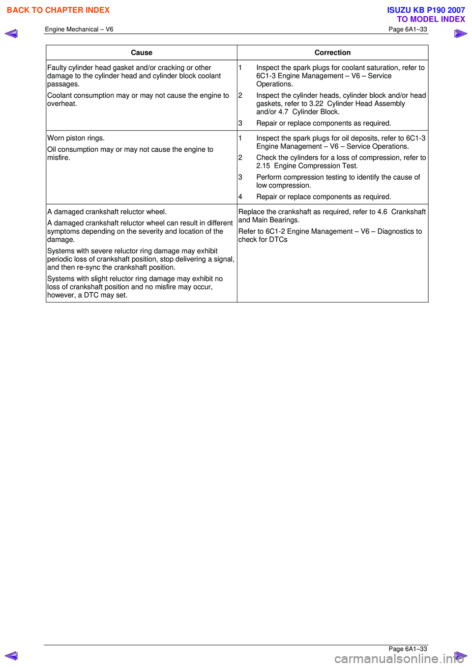
Engine Mechanical – V6 Page 6A1–33
Page 6A1–33
Cause Correction
Faulty cylinder head gasket and/or cracking or other
damage to the cylinder head and cylinder block coolant
passages.
Coolant consumption may or may not cause the engine to
overheat. 1 Inspect the spark plugs for
coolant saturation, refer to
6C1-3 Engine Management – V6 – Service
Operations.
2 Inspect the cylinder heads, cylinder block and/or head gaskets, refer to 3.22 Cylinder Head Assembly
and/or 4.7 Cylinder Block.
3 Repair or replace components as required.
Worn piston rings.
Oil consumption may or ma y not cause the engine to
misfire. 1 Inspect the spark plugs for oil deposits, refer to 6C1-3
Engine Management – V6 – Service Operations.
2 Check the cylinders for a loss of compression, refer to 2.15 Engine Compression Test.
3 Perform compression testing to identify the cause of
low compression.
4 Repair or replace components as required.
A damaged crankshaft reluctor wheel.
A damaged crankshaft reluctor wheel can result in different
symptoms depending on the severity and location of the
damage.
Systems with severe relu ctor ring damage may exhibit
periodic loss of crankshaft posit ion, stop delivering a signal,
and then re-sync the crankshaft position.
Systems with slight reluctor ring damage may exhibit no
loss of crankshaft position and no misfire may occur,
however, a DTC may set. Replace the crankshaft as required, refer to 4.6 Crankshaft
and Main Bearings.
Refer to 6C1-2 Engine Management – V6 – Diagnostics to
check for DTCs
BACK TO CHAPTER INDEX
TO MODEL INDEX
ISUZU KB P190 2007