2007 ISUZU KB P190 DTC CHECK
[x] Cancel search: DTC CHECKPage 3301 of 6020

Engine Management – V6 – Diagnostics Page 6C1-2–23
• there is no Current DTC but a History DTC is stored.
Diagnostic Table
Checks Actions
Preliminary
• Perform the preliminary checks. Refer to 4.3 Preliminary Checks in this
Section.
• Gather information from the customer regarding the conditions that trigger the
intermittent fault such as:
• At what engine or ambient temperature range does the fault occur?
• Does the fault occur when operating aftermarket electrical equipment inside
the vehicle?
• Does the fault occur on rough roads or in wet road conditions?
• If the intermittent fault is a start and then stall condition, check the immobiliser
system. Refer to 11A Immobiliser.
Tech 2 Tests The following are lists of Tech 2 diagnostic tests that may be used to diagnose
intermittent faults:
• W riggle test the suspected wiring harness and connectors while observing Tech 2
operating parameters. If Tech 2 read-out fluctuates during this procedure, check
the tested wiring harness circuit for a loose connection.
• Observe the freeze frame / failure records for the suspected history DTC and then
operate the vehicle in the conditions that triggers the intermittent fault while an
assistant observes the suspected Tech 2 operating parameter data.
• Capture and store data in the snapshot mode when the fault occurs. The stored
data may be played back at a slower rate to aid diagnostics. Refer to Tech 2 User
Instructions for further information on the Snapshot function.
• Compare the engine operating parameters of the engine being diagnosed to the
engine operating parameters of a known good engine.
Malfunction Indicator Lamp The following conditions may cause an intermittent Malfunction Indicator Lamp fault with no DTC listed:
• Electromagnetic interference (EMI) caused by a faulty relay, ECM controlled
solenoid, switch or other external source.
• Incorrect installation of aftermarket electrical equipment such as the following:
• mobile phones,
• lights, or
• radio equipment.
• ECM grounds are loose.
BACK TO CHAPTER INDEX
TO MODEL INDEX
ISUZU KB P190 2007
Page 3305 of 6020
Engine Management – V6 – Diagnostics Page 6C1-2–27
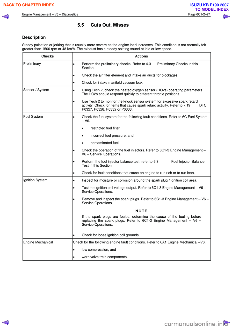
5.5 Cuts Out, Misses
Description
Steady pulsation or jerking that is usually more severe as the engine load increases. This condition is not normally felt
greater than 1500 rpm or 48 km/h. The exhaust has a steady spitting sound at idle or low speed.
Checks Actions
Preliminary • Perform the preliminary checks. Refer to 4.3 Preliminary Checks in this
Section.
• Check the air filter element and intake air ducts for blockages.
• Check for intake manifold vacuum leak.
Sensor / System
• Using Tech 2, check the heated oxygen sensor (HO2s) operating parameters.
The HO2s should respond quickly to different throttle positions.
• Use Tech 2 to monitor the knock sensor system for excessive spark retard
activity. Check for items that cause spark retard activity. Refer to 7.19 DTC
P0327, P0328, P0332 or P0333.
Fuel System • Check the fuel system for the following fault conditions. Refer to 6C Fuel System
– V6.
• restricted fuel filter,
• incorrect fuel pressure, and
• contaminated fuel.
• Check the operation of the fuel injectors. Refer to 6C1-3 Engine Management –
V6 – Service Operations.
• Perform the fuel injector balance test, refer to 6.3 Fuel Injector Balance
Test in this Section.
• Check for fault conditions that cause an engine to run rich or to run lean.
Ignition System
• Inspect for moisture or corrosion around the spark plug / ignition coil area.
• Test the ignition coil voltage output. Refer to 6C1-3 Engine Management – V6 –
Service Operations.
• Remove and inspect the spark plugs. Refer to 6C1-3 Engine Management – V6 –
Service Operations.
NOTE
If the spark plugs are fouled, determine the cause of the fouling before
replacing the spark plugs. Refer to 6C1-3 Engine Management – V6 –
Service Operations.
• Check for loose ignition coil grounds.
Engine Mechanical Check for the following engine fault conditions. Refer to 6A1 Engine Mechanical –V6.
• low compression, and
• worn valve train components.
BACK TO CHAPTER INDEX
TO MODEL INDEX
ISUZU KB P190 2007
Page 3308 of 6020
Engine Management – V6 – Diagnostics Page 6C1-2–30
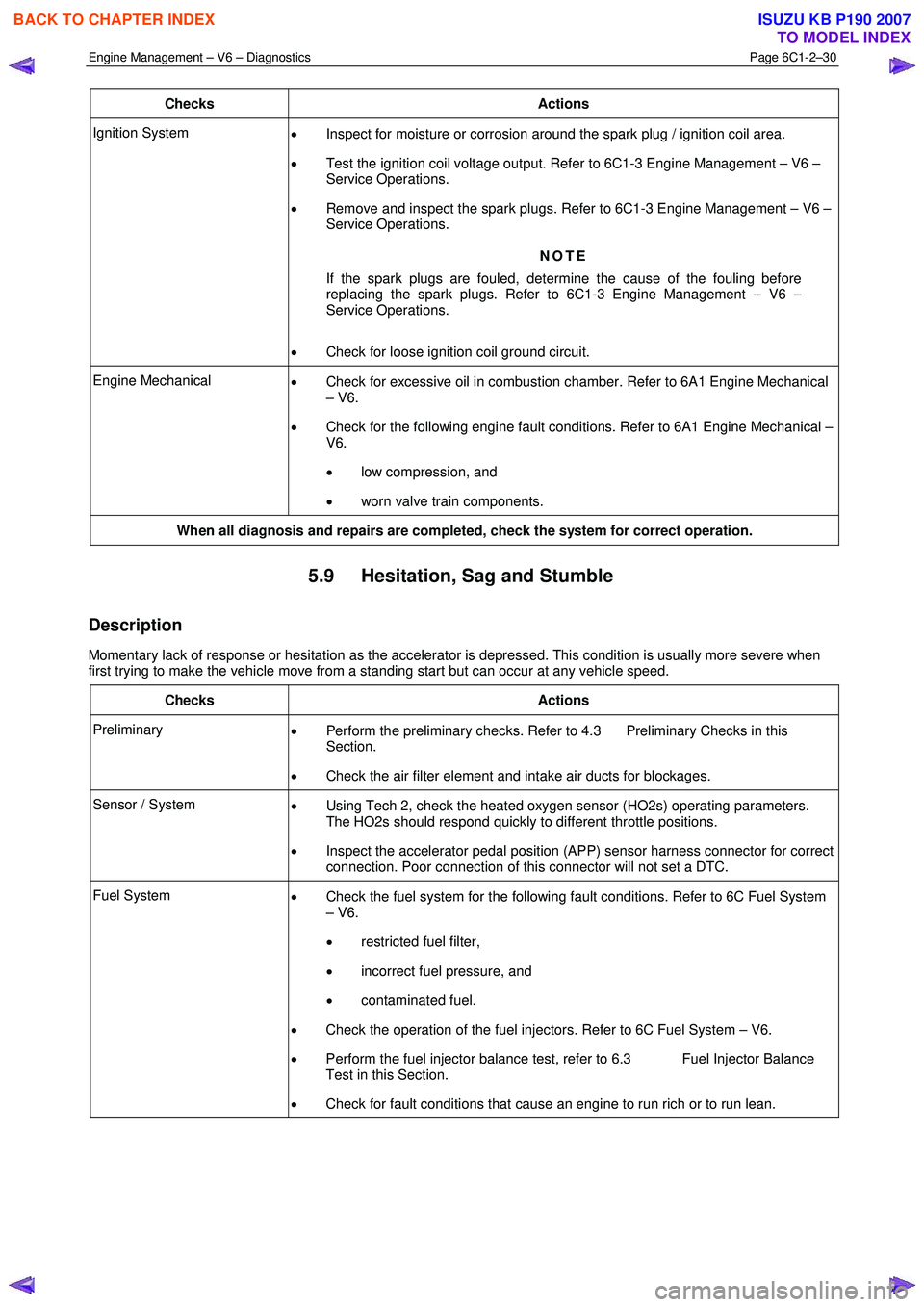
Checks Actions
Ignition System
• Inspect for moisture or corrosion around the spark plug / ignition coil area.
• Test the ignition coil voltage output. Refer to 6C1-3 Engine Management – V6 –
Service Operations.
• Remove and inspect the spark plugs. Refer to 6C1-3 Engine Management – V6 –
Service Operations.
NOTE
If the spark plugs are fouled, determine the cause of the fouling before
replacing the spark plugs. Refer to 6C1-3 Engine Management – V6 –
Service Operations.
• Check for loose ignition coil ground circuit.
Engine Mechanical
• Check for excessive oil in combustion chamber. Refer to 6A1 Engine Mechanical
– V6.
• Check for the following engine fault conditions. Refer to 6A1 Engine Mechanical –
V6.
• low compression, and
• worn valve train components.
When all diagnosis and repairs are completed, check the system for correct operation.
5.9 Hesitation, Sag and Stumble
Description
Momentary lack of response or hesitation as the accelerator is depressed. This condition is usually more severe when
first trying to make the vehicle move from a standing start but can occur at any vehicle speed.
Checks Actions
Preliminary • Perform the preliminary checks. Refer to 4.3 Preliminary Checks in this
Section.
• Check the air filter element and intake air ducts for blockages.
Sensor / System
• Using Tech 2, check the heated oxygen sensor (HO2s) operating parameters.
The HO2s should respond quickly to different throttle positions.
• Inspect the accelerator pedal position (APP) sensor harness connector for correct
connection. Poor connection of this connector will not set a DTC.
Fuel System • Check the fuel system for the following fault conditions. Refer to 6C Fuel System
– V6.
• restricted fuel filter,
• incorrect fuel pressure, and
• contaminated fuel.
• Check the operation of the fuel injectors. Refer to 6C Fuel System – V6.
• Perform the fuel injector balance test, refer to 6.3 Fuel Injector Balance
Test in this Section.
• Check for fault conditions that cause an engine to run rich or to run lean.
BACK TO CHAPTER INDEX
TO MODEL INDEX
ISUZU KB P190 2007
Page 3309 of 6020
Engine Management – V6 – Diagnostics Page 6C1-2–31
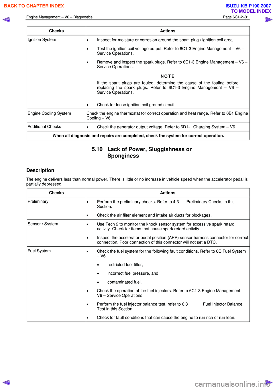
Checks Actions
Ignition System
• Inspect for moisture or corrosion around the spark plug / ignition coil area.
• Test the ignition coil voltage output. Refer to 6C1-3 Engine Management – V6 –
Service Operations.
• Remove and inspect the spark plugs. Refer to 6C1-3 Engine Management – V6 –
Service Operations.
NOTE
If the spark plugs are fouled, determine the cause of the fouling before
replacing the spark plugs. Refer to 6C1-3 Engine Management – V6 –
Service Operations.
• Check for loose ignition coil ground circuit.
Engine Cooling System Check the engine thermostat for correct operation and heat range. Refer to 6B1 Engine
Cooling – V6.
Additional Checks • Check the generator output voltage. Refer to 6D1-1 Charging System – V6.
When all diagnosis and repairs are completed, check the system for correct operation.
5.10 Lack of Power, Sluggishness or
Sponginess
Description
The engine delivers less than normal power. There is little or no increase in vehicle speed when the accelerator pedal is
partially depressed.
Checks Actions
Preliminary • Perform the preliminary checks. Refer to 4.3 Preliminary Checks in this
Section.
• Check the air filter element and intake air ducts for blockages.
Sensor / System
• Use Tech 2 to monitor the knock sensor system for excessive spark retard
activity. Check for items that cause spark retard activity.
• Inspect the accelerator pedal position (APP) sensor harness connector for correct
connection. Poor connection of this connector will not set a DTC.
Fuel System • Check the fuel system for the following fault conditions. Refer to 6C Fuel System
– V6.
• restricted fuel filter,
• incorrect fuel pressure, and
• contaminated fuel.
• Check the operation of the fuel injectors. Refer to 6C1-3 Engine Management –
V6 – Service Operations.
• Perform the fuel injector balance test, refer to 6.3 Fuel Injector Balance
Test in this Section.
• Check for fault conditions that can cause the engine to run rich or run lean.
BACK TO CHAPTER INDEX
TO MODEL INDEX
ISUZU KB P190 2007
Page 3315 of 6020
Engine Management – V6 – Diagnostics Page 6C1-2–37
6 Functional Checks
6.1 General Information
The items detailed in the following pages are to be used when there is a customer complaint and there are no diagnostic
trouble codes set, or one or more of the Tech 2 data values are not within the typical values. They are also to be used
when instructed from a DTC table. Before using these tables, you should refer to 5 Symptoms Diagnostics in this
Section, which may direct you to using the following functional checks.
The purpose of these tables is to diagnose engine control module (ECM) controlled components or sub-systems that do
not have diagnostic trouble codes assigned to them. Another purpose of these tables is for Technicians who feel
confident that a particular part of the sub-system is not operating properly and wants only to check that particular item
for proper operation without going through lengthy diagnostic procedures.
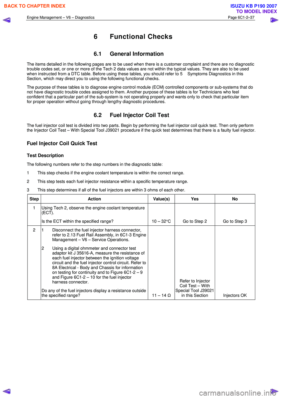
6.2 Fuel Injector Coil Test
The fuel injector coil test is divided into two parts. Begin by performing the fuel injector coil quick test. Then only perform
the Injector Coil Test – W ith Special Tool J39021 procedure if the quick test determines that there is a faulty fuel injector.
Fuel Injector Coil Quick Test
Test Description
The following numbers refer to the step numbers in the diagnostic table:
1 This step checks if the engine coolant temperature is within the correct range.
2 This step tests each fuel injector resistance within a specific temperature range.
3 This step determines if all of the fuel injectors are within 3 ohms of each other.
Step Action Value(s) Yes No
1 Using Tech 2, observe the engine coolant temperature
(ECT).
Is the ECT within the specified range? 10 – 32 °C Go to Step 2 Go to Step 3
2 1 Disconnect the fuel injector harness connector,
refer to 2.13 Fuel Rail Assembly, in 6C1-3 Engine
Management – V6 – Service Operations.
2 Using a digital ohmmeter and connector test adaptor kit J 35616-A, measure the resistance of
each fuel injector between the ignition voltage
circuit and the fuel injector control circuit. Refer to
8A Electrical - Body and Chassis for information
on testing for continuity and to Figure 6C1-2 – 9
and Figure 6C1-2 – 10 for the fuel injector
harness connector.
Do any of the fuel injectors display a resistance outside
the specified range? 11 – 14 ΩRefer to Injector
Coil Test – W ith
Special Tool J39021 in this Section Injectors OK
BACK TO CHAPTER INDEX
TO MODEL INDEX
ISUZU KB P190 2007
Page 3326 of 6020
Engine Management – V6 – Diagnostics Page 6C1-2–48
Additional Information
• Use the J 35616-B Connector Test Adapter Kit for any test that requires probing the ECM harness connector or a
component harness connector.
• Inspect the ignition coils for aftermarket devices. An aftermarket device connected to the ignition coil circuits, may
cause a condition with the ignition coils.
• For an intermittent fault condition, refer to 5.2 Intermittent Fault Conditions in this Section.
• To assist diagnosis, refer to 3 W iring Diagrams and Connector Charts in this Section, for the system wiring
diagram and connector charts.
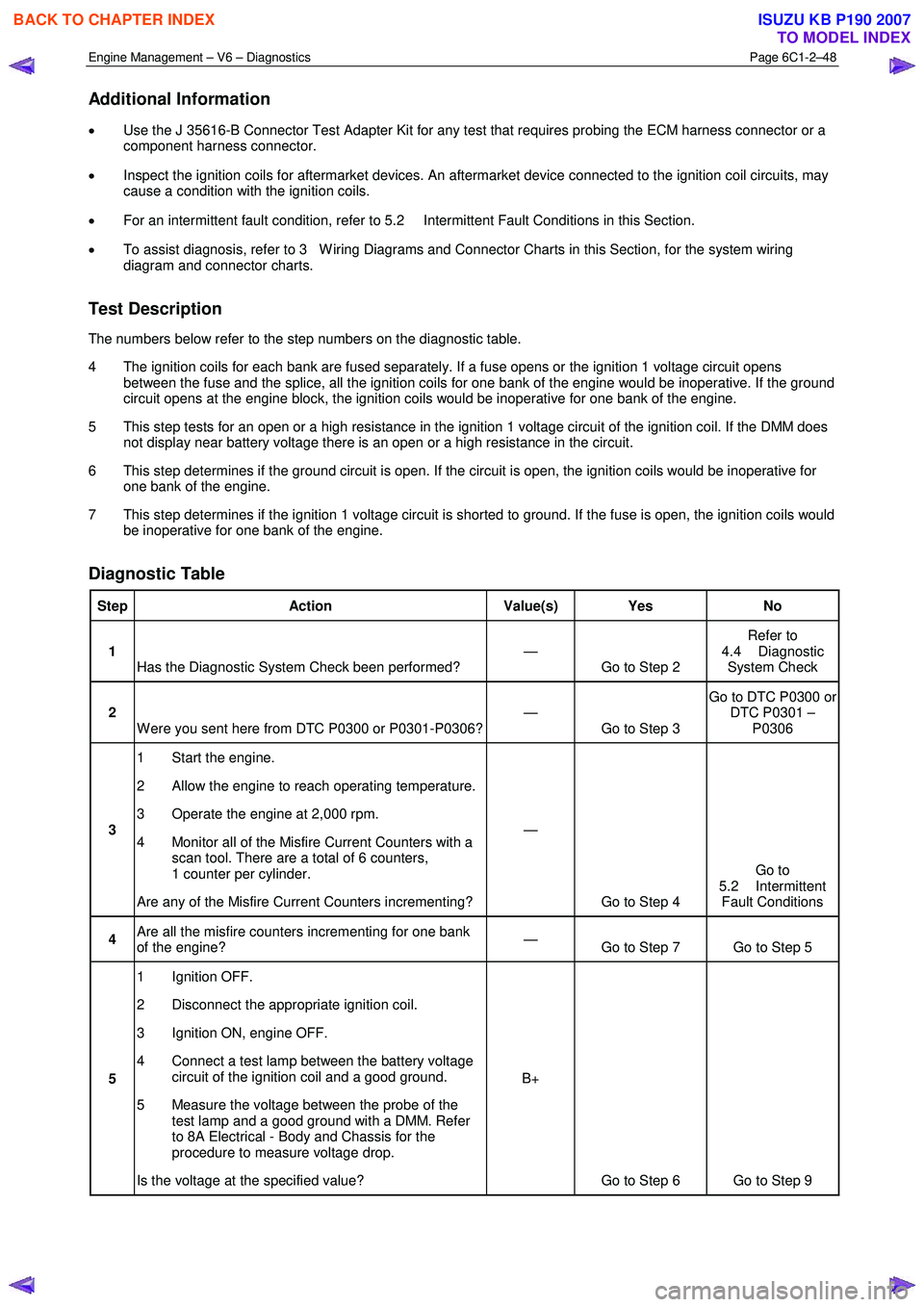
Test Description
The numbers below refer to the step numbers on the diagnostic table.
4 The ignition coils for each bank are fused separately. If a fuse opens or the ignition 1 voltage circuit opens between the fuse and the splice, all the ignition coils for one bank of the engine would be inoperative. If the ground
circuit opens at the engine block, the ignition coils would be inoperative for one bank of the engine.
5 This step tests for an open or a high resistance in the ignition 1 voltage circuit of the ignition coil. If the DMM does not display near battery voltage there is an open or a high resistance in the circuit.
6 This step determines if the ground circuit is open. If the circuit is open, the ignition coils would be inoperative for one bank of the engine.
7 This step determines if the ignition 1 voltage circuit is shorted to ground. If the fuse is open, the ignition coils would be inoperative for one bank of the engine.
Diagnostic Table
Step Action Value(s) Yes No
1
Has the Diagnostic System Check been performed? —
Go to Step 2 Refer to
4.4 Diagnostic System Check
2 W ere you sent here from DTC P0300 or P0301-P0306? —
Go to Step 3 Go to DTC P0300 or
DTC P0301 – P0306
3 1 Start the engine.
2 Allow the engine to reach operating temperature.
3 Operate the engine at 2,000 rpm.
4 Monitor all of the Misfire Current Counters with a scan tool. There are a total of 6 counters,
1 counter per cylinder.
Are any of the Misfire Current Counters incrementing? —
Go to Step 4 Go to
5.2 Intermittent Fault Conditions
4 Are all the misfire counters incrementing for one bank
of the engine? —
Go to Step 7 Go to Step 5
5 1 Ignition OFF.
2 Disconnect the appropriate ignition coil.
3 Ignition ON, engine OFF.
4 Connect a test lamp between the battery voltage circuit of the ignition coil and a good ground.
5 Measure the voltage between the probe of the test lamp and a good ground with a DMM. Refer
to 8A Electrical - Body and Chassis for the
procedure to measure voltage drop.
Is the voltage at the specified value? B+
Go to Step 6 Go to Step 9
BACK TO CHAPTER INDEX
TO MODEL INDEX
ISUZU KB P190 2007
Page 3340 of 6020
Engine Management – V6 – Diagnostics Page 6C1-2–62
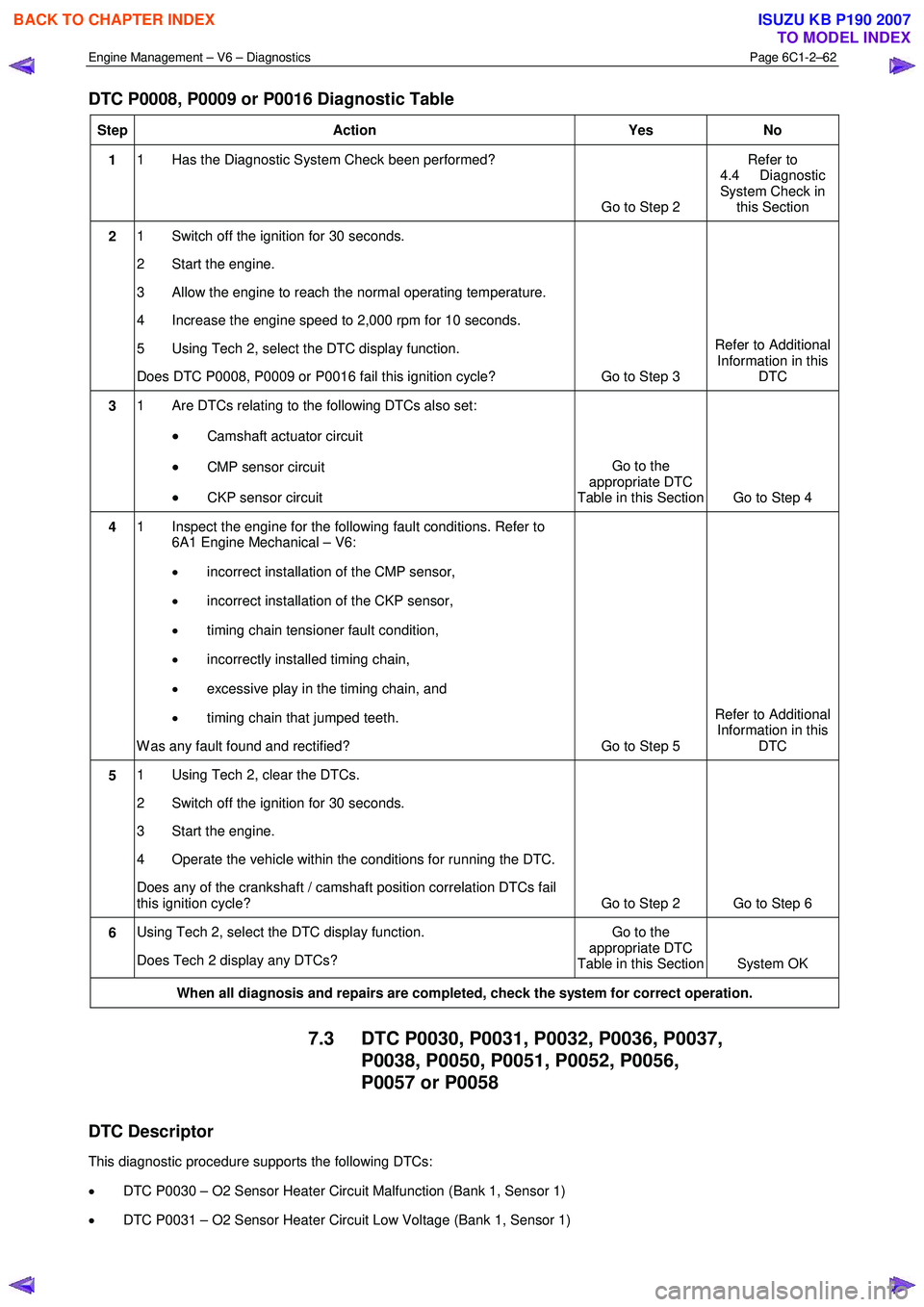
DTC P0008, P0009 or P0016 Diagnostic Table
Step Action Yes No
1 1 Has the Diagnostic System Check been performed?
Go to Step 2 Refer to
4.4 Diagnostic
System Check in this Section
2 1 Switch off the ignition for 30 seconds.
2 Start the engine.
3 Allow the engine to reach the normal operating temperature.
4 Increase the engine speed to 2,000 rpm for 10 seconds.
5 Using Tech 2, select the DTC display function.
Does DTC P0008, P0009 or P0016 fail this ignition cycle? Go to Step 3 Refer to Additional
Information in this DTC
3 1 Are DTCs relating to the following DTCs also set:
• Camshaft actuator circuit
• CMP sensor circuit
• CKP sensor circuit Go to the
appropriate DTC
Table in this Section Go to Step 4
4 1 Inspect the engine for the following fault conditions. Refer to
6A1 Engine Mechanical – V6:
• incorrect installation of the CMP sensor,
• incorrect installation of the CKP sensor,
• timing chain tensioner fault condition,
• incorrectly installed timing chain,
• excessive play in the timing chain, and
• timing chain that jumped teeth.
W as any fault found and rectified? Go to Step 5 Refer to Additional
Information in this DTC
5 1 Using Tech 2, clear the DTCs.
2 Switch off the ignition for 30 seconds.
3 Start the engine.
4 Operate the vehicle within the conditions for running the DTC.
Does any of the crankshaft / camshaft position correlation DTCs fail
this ignition cycle? Go to Step 2 Go to Step 6
6 Using Tech 2, select the DTC display function.
Does Tech 2 display any DTCs? Go to the
appropriate DTC
Table in this Section System OK
When all diagnosis and repairs are completed, check the system for correct operation.
7.3 DTC P0030, P0031, P0032, P0036, P0037,
P0038, P0050, P0051, P0052, P0056,
P0057 or P0058
DTC Descriptor
This diagnostic procedure supports the following DTCs:
• DTC P0030 – O2 Sensor Heater Circuit Malfunction (Bank 1, Sensor 1)
• DTC P0031 – O2 Sensor Heater Circuit Low Voltage (Bank 1, Sensor 1)
BACK TO CHAPTER INDEX
TO MODEL INDEX
ISUZU KB P190 2007
Page 3342 of 6020
Engine Management – V6 – Diagnostics Page 6C1-2–64
• Inspect the HO2S wiring harness for contact with the exhaust system.
• The front and the rear HO2Ss have a separate fuse connection. If both front or both the rear DTCs are set, the
appropriate HO2S ignition voltage circuit may be open.
• Since fault condition in a wiring connector may trigger DTCs, always test the connectors related to this diagnostic
procedure for shorted terminals or poor wiring connection before replacing any component. Refer to 8A Electrical -
Body and Chassis for information on electrical fault diagnosis.
• To assist diagnosis, refer to 3 W iring Diagrams and Connector Charts in this Section, for the system wiring
diagram and connector charts.
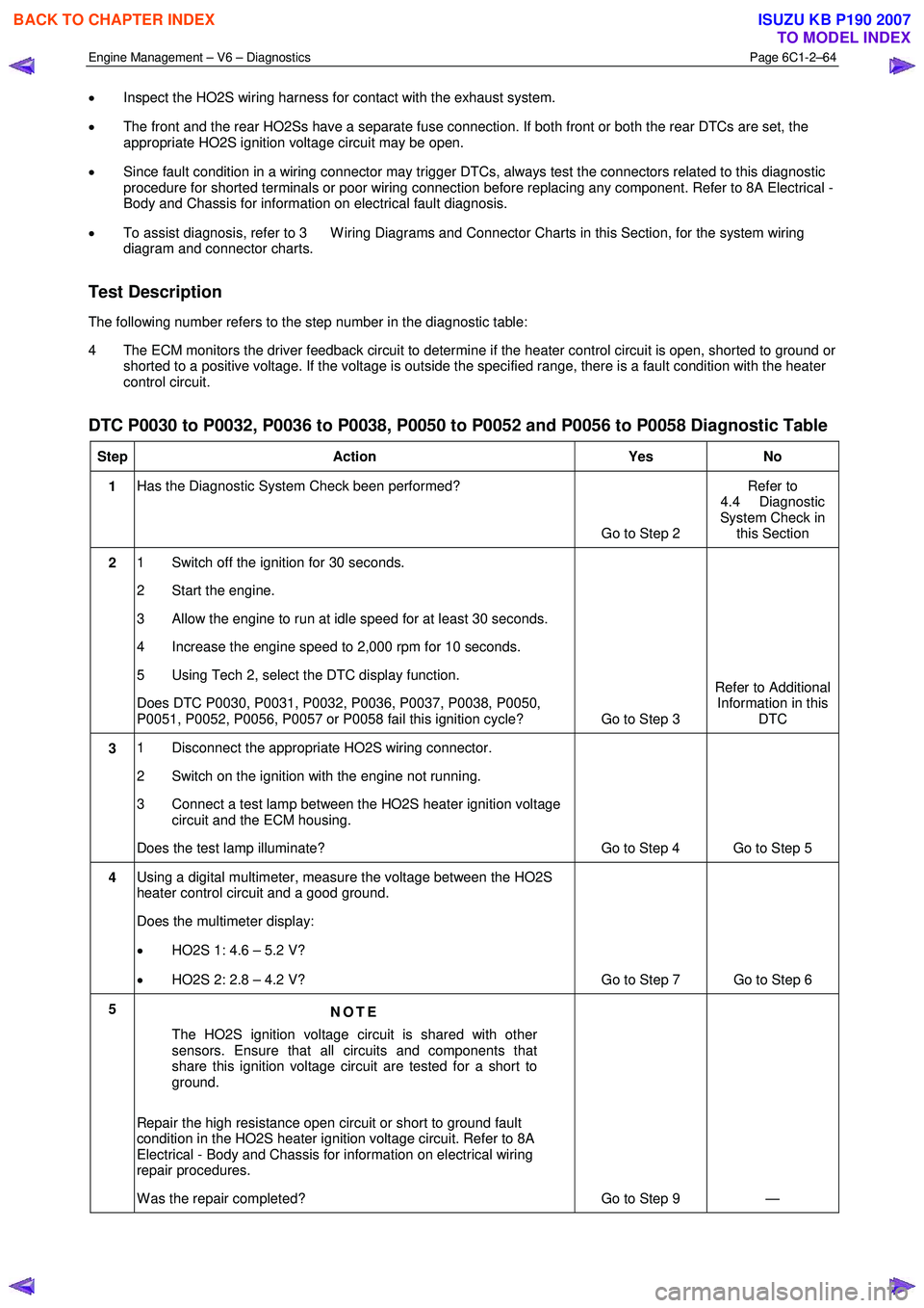
Test Description
The following number refers to the step number in the diagnostic table:
4 The ECM monitors the driver feedback circuit to determine if the heater control circuit is open, shorted to ground or shorted to a positive voltage. If the voltage is outside the specified range, there is a fault condition with the heater
control circuit.
DTC P0030 to P0032, P0036 to P0038, P0050 to P0052 and P0056 to P0058 Diagnostic Table
Step Action Yes No
1 Has the Diagnostic System Check been performed?
Go to Step 2 Refer to
4.4 Diagnostic
System Check in this Section
2 1 Switch off the ignition for 30 seconds.
2 Start the engine.
3 Allow the engine to run at idle speed for at least 30 seconds.
4 Increase the engine speed to 2,000 rpm for 10 seconds.
5 Using Tech 2, select the DTC display function.
Does DTC P0030, P0031, P0032, P0036, P0037, P0038, P0050,
P0051, P0052, P0056, P0057 or P0058 fail this ignition cycle? Go to Step 3 Refer to Additional
Information in this DTC
3 1 Disconnect the appropriate HO2S wiring connector.
2 Switch on the ignition with the engine not running.
3 Connect a test lamp between the HO2S heater ignition voltage circuit and the ECM housing.
Does the test lamp illuminate? Go to Step 4 Go to Step 5
4 Using a digital multimeter, measure the voltage between the HO2S
heater control circuit and a good ground.
Does the multimeter display:
• HO2S 1: 4.6 – 5.2 V?
• HO2S 2: 2.8 – 4.2 V? Go to Step 7 Go to Step 6
5
NOTE
The HO2S ignition voltage circuit is shared with other
sensors. Ensure that all circuits and components that
share this ignition voltage circuit are tested for a short to
ground.
Repair the high resistance open circuit or short to ground fault
condition in the HO2S heater ignition voltage circuit. Refer to 8A
Electrical - Body and Chassis for information on electrical wiring
repair procedures.
W as the repair completed? Go to Step 9 —
BACK TO CHAPTER INDEX
TO MODEL INDEX
ISUZU KB P190 2007