2007 ISUZU KB P190 engine
[x] Cancel search: enginePage 1068 of 6020
6E-34 Engine Control System (4JH1)
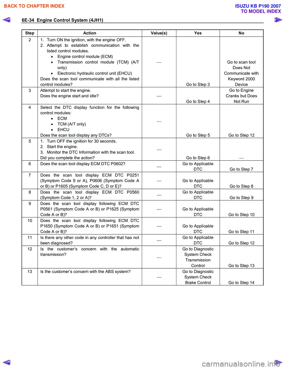
Step Action Value(s) Yes No
2 1. Turn ON the ignition, with the engine OFF.
2. Attempt to establish communication with the listed control modules. • Engine control module (ECM)
• Transmission control module (TCM) (A/T
only)
• Electronic hydraulic control unit (EHCU)
Does the scan tool communicate with all the listed
control modules?
Go to Step 3 Go to scan tool
Does Not
Communicate with Keyword 2000 Device
3 Attempt to start the engine. Does the engine start and idle?
Go to Step 4 Go to Engine
Cranks but Does Not Run
4 Select the DTC display function for the following control modules: • ECM
• TCM (A/T only)
• EHCU
Does the scan tool display any DTCs?
Go to Step 5 Go to Step 12
5 1. Turn OFF the ignition for 30 seconds. 2. Start the engine.
3. Monitor the DTC Information with the scan tool.
Did you complete the action?
Go to Step 6
6 Does the scan tool display ECM DTC P0602?
Go to Applicable
DTC Go to Step 7
7 Does the scan tool display ECM DTC P0251 (Symptom Code 9 or A), P0606 (Symptom Code A
or B) or P1605 (Symptom Code C, D or E)?
Go to Applicable
DTC Go to Step 8
8 Does the scan tool display ECM DTC P0560 (Symptom Code 1, 2 or A)?
Go to Applicable
DTC Go to Step 9
9 Does the scan tool display following ECM DTC
P0561 (Symptom Code A or B) or P1625 (Symptom
Code A or B)?
Go to Applicable
DTC Go to Step 10
10 Does the scan tool display following ECM DTC P1650 (Symptom Code A or B) or P1651 (Symptom
Code A or B)?
Go to Applicable
DTC Go to Step 11
11 Is there any other code in any controller that has not
been diagnosed?
Go to Applicable
DTC Go to Step 12
12 Is the customer’s concern with the automatic
transmission? Go to Diagnostic
System Check Transmission Control Go to Step 13
13 Is the customer’s concern with the ABS system?
Go to Diagnostic
System Check Brake Control Go to Step 14
BACK TO CHAPTER INDEX
TO MODEL INDEX
ISUZU KB P190 2007
Page 1069 of 6020
Engine Control System (4JH1) 6E-35
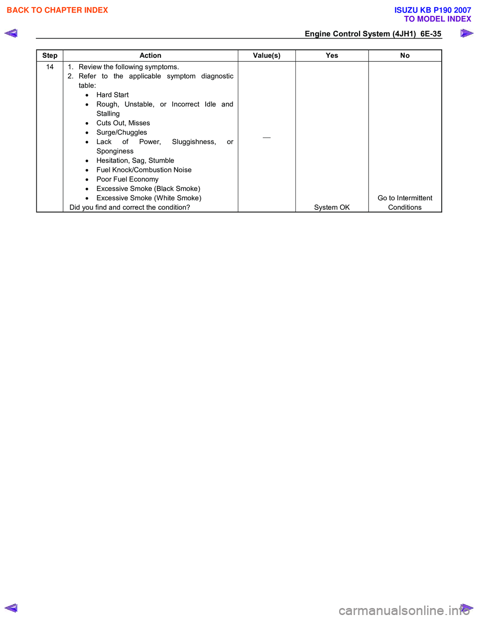
Step Action Value(s) Yes No
14 1. Review the following symptoms.
2. Refer to the applicable symptom diagnostic table: • Hard Start
• Rough, Unstable, or Incorrect Idle and
Stalling
• Cuts Out, Misses
• Surge/Chuggles
• Lack of Power, Sluggishness, or
Sponginess
• Hesitation, Sag, Stumble
• Fuel Knock/Combustion Noise
• Poor Fuel Economy
• Excessive Smoke (Black Smoke)
• Excessive Smoke (W hite Smoke)
Did you find and correct the condition?
System OK Go to Intermittent
Conditions
BACK TO CHAPTER INDEX
TO MODEL INDEX
ISUZU KB P190 2007
Page 1070 of 6020
6E-36 Engine Control System (4JH1)
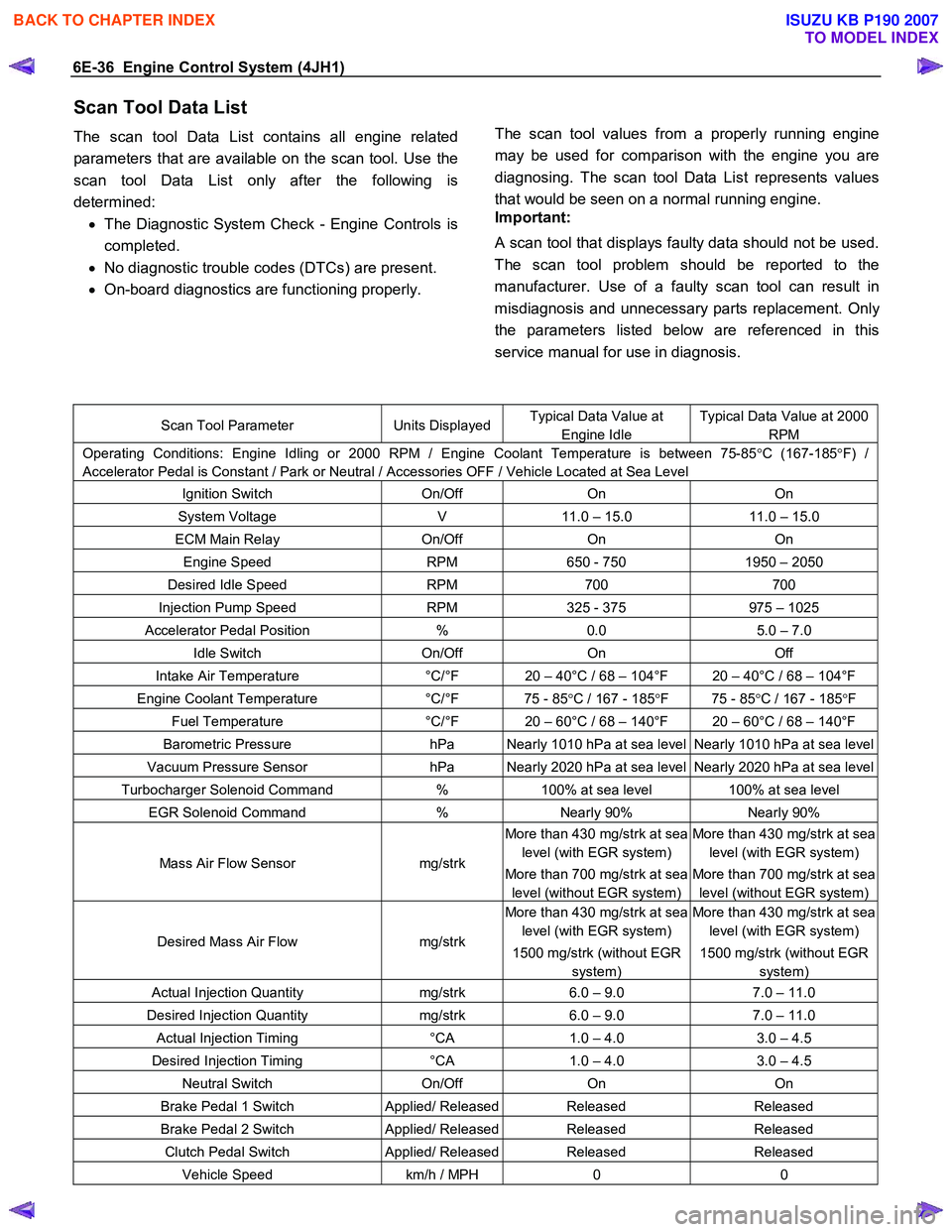
Scan Tool Data List
The scan tool Data List contains all engine related
parameters that are available on the scan tool. Use the
scan tool Data List only after the following is
determined: • The Diagnostic System Check - Engine Controls is
completed.
• No diagnostic trouble codes (DTCs) are present.
• On-board diagnostics are functioning properly.
The scan tool values from a properly running engine
may be used for comparison with the engine you are
diagnosing. The scan tool Data List represents values
that would be seen on a normal running engine.
Important:
A scan tool that displays faulty data should not be used.
The scan tool problem should be reported to the
manufacturer. Use of a faulty scan tool can result in
misdiagnosis and unnecessary parts replacement. Onl
y
the parameters listed below are referenced in this
service manual for use in diagnosis.
Scan Tool Parameter Units DisplayedTypical Data Value at
Engine Idle
Typical Data Value at 2000
RPM
Operating Conditions: Engine Idling or 2000 RPM / Engine Coolant Temperature is between 75-85 °C (167-185 °F) /
Accelerator Pedal is Constant / Park or Neutral / Accessories OFF / Vehicle Located at Sea Level
Ignition Switch On/Off On On
System Voltage V 11.0 – 15.0 11.0 – 15.0
ECM Main Relay On/Off On On
Engine Speed RPM 650 - 750 1950 – 2050
Desired Idle Speed RPM 700 700
Injection Pump Speed RPM 325 - 375 975 – 1025
Accelerator Pedal Position % 0.0 5.0 – 7.0
Idle Switch On/Off On Off
Intake Air Temperature °C/°F 20 – 40°C / 68 – 104°F 20 – 40°C / 68 – 104°F
Engine Coolant Temperature °C/°F 75 - 85 °C / 167 - 185 °F 75 - 85 °C / 167 - 185 °F
Fuel Temperature °C/°F 20 – 60°C / 68 – 140°F 20 – 60°C / 68 – 140°F
Barometric Pressure hPa Nearly 1010 hPa at sea level Nearly 1010 hPa at sea level
Vacuum Pressure Sensor hPa Nearly 2020 hPa at sea level Nearly 2020 hPa at sea level
Turbocharger Solenoid Command % 100% at sea level 100% at sea level
EGR Solenoid Command % Nearly 90% Nearly 90%
Mass Air Flow Sensor mg/strk
More than 430 mg/strk at sea
level (with EGR system)
More than 700 mg/strk at sea
level (without EGR system)
More than 430 mg/strk at sea
level (with EGR system)
More than 700 mg/strk at sea
level (without EGR system)
Desired Mass Air Flow mg/strk
More than 430 mg/strk at sea
level (with EGR system)
1500 mg/strk (without EGR
system)
More than 430 mg/strk at sea
level (with EGR system)
1500 mg/strk (without EGR
system)
Actual Injection Quantity mg/strk 6.0 – 9.0 7.0 – 11.0
Desired Injection Quantity mg/strk 6.0 – 9.0 7.0 – 11.0
Actual Injection Timing °CA 1.0 – 4.0 3.0 – 4.5
Desired Injection Timing °CA 1.0 – 4.0 3.0 – 4.5
Neutral Switch On/Off On On
Brake Pedal 1 Switch Applied/ ReleasedReleased Released
Brake Pedal 2 Switch Applied/ ReleasedReleased Released
Clutch Pedal Switch Applied/ ReleasedReleased Released
Vehicle Speed km/h / MPH 0 0
BACK TO CHAPTER INDEX
TO MODEL INDEX
ISUZU KB P190 2007
Page 1071 of 6020
Engine Control System (4JH1) 6E-37
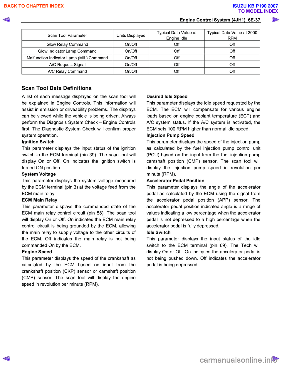
Scan Tool Parameter Units DisplayedTypical Data Value at
Engine Idle
Typical Data Value at 2000
RPM
Glow Relay Command On/Off Off Off
Glow Indicator Lamp Command On/Off Off Off
Malfunction Indicator Lamp (MIL) Command On/Off Off Off
A/C Request Signal On/Off Off Off
A/C Relay Command On/Off Off Off
Scan Tool Data Definitions
A list of each message displayed on the scan tool will
be explained in Engine Controls. This information will
assist in emission or driveability problems. The displays
can be viewed while the vehicle is being driven. Always
perform the Diagnosis System Check – Engine Controls
first. The Diagnostic System Check will confirm prope
r
system operation.
Ignition Switch
This parameter displays the input status of the ignition
switch to the ECM terminal (pin 39). The scan tool will
display On or Off. On indicates the ignition switch is
turned ON position.
System Voltage
This parameter displays the system voltage measured
by the ECM terminal (pin 3) at the voltage feed from the
ECM main relay.
ECM Main Relay
This parameter displays the commanded state of the
ECM main relay control circuit (pin 58). The scan tool
will display On or Off. On indicates the ECM main rela
y
control circuit is being grounded by the ECM, allowing
the main relay to supply voltage to the other circuits o
f
the ECM. Off indicates the main relay is not being
commanded On by the ECM.
Engine Speed
This parameter displays the speed of the crankshaft as
calculated by the ECM based on input from the
crankshaft position (CKP) sensor or camshaft position
(CMP) sensor. The scan tool will display the engine
speed in revolution per minute (RPM).
Desired Idle Speed
This parameter displays the idle speed requested by the
ECM. The ECM will compensate for various engine
loads based on engine coolant temperature (ECT) and
A/C system status. If the A/C system is activated, the
ECM sets 100 RPM higher than normal idle speed.
Injection Pump Speed
This parameter displays the speed of the injection pump
as calculated by the fuel injection pump control unit
(PCU) based on the input from the fuel injection pump
camshaft position (CMP) sensor. The scan tool will
display the injection pump speed in revolution pe
r
minute (RPM).
Accelerator Pedal Position
This parameter displays the angle of the accelerato
r
pedal as calculated by the ECM using the signal from
the accelerator pedal position (APP) sensor. The
accelerator pedal position indicated angle is a range o
f
values indicating a low percentage when the accelerator
pedal is not depressed to a high percentage when the
accelerator pedal is fully depressed.
Idle Switch
This parameter displays the input status of the idle
switch to the ECM terminal (pin 69). The Tech will
display On or Off. On indicates the accelerator pedal is
not being pushed down. Off indicates the accelerato
r
pedal is being depressed.
BACK TO CHAPTER INDEX
TO MODEL INDEX
ISUZU KB P190 2007
Page 1072 of 6020
6E-38 Engine Control System (4JH1)
Intake Air Temperature
This parameter displays the temperature of the intake
air based on a voltage input from the intake ai
r
temperature (IAT) sensor to the ECM. The scan tool will
display a low temperature when signal voltage is high,
and high temperature when the signal voltage is low.
Note that the IAT sensor is internal to the mass air flo
w
(MAF) sensor and the MAF sensor is heated.
Engine Coolant Temperature
This parameter displays the temperature of the engine
coolant based on a voltage input from the engine
coolant temperature (ECT) sensor to the ECM. The
scan tool will display a low temperature when the signal
voltage is high, and a high temperature when the signal
voltage is low.
Fuel Temperature
This parameter displays the temperature of the fuel as
calculated by the fuel injection pump control unit (PCU)
using the signal from the fuel temperature sensor inside
of the PCU.
Barometric Pressure
This parameter displays the barometric pressure as
calculated by the ECM using the signal from the
barometric pressure (BARO) sensor inside of the ECM.
Vacuum Pressure Sensor (High altitude
specification only)
This parameter displays the amount of the vacuum
pressure to the turbocharger wastegate valve. W hen a
high vacuum pressure at a low vacuum pressure
amount to the turbocharger wastegate valve. The scan
tool will display doubled barometric pressure when the
ignition is ON with the engine OFF.
Turbocharger Solenoid Command (High altitude
specification only)
This parameter displays the turbocharger solenoid
valuve control duty ratio commanded by the ECM
terminal (pin 96) using the signal from various senso
r
inputs. W hen a low duty ratio, vacuum pressure to the
turbocharger wastegate valve is controlled to increase.
W hen a high duty ratio, vacuum pressure to the
turbochager wastegate valve is controlled to reduce.
EGR Solenoid Command
This parameter displays the EGR solenoid valve control
duty ratio commanded by the ECM terminal (pin 97)
using the signal from engine speed, and injection
volume and various sensor inputs. W hen a small dut
y
ratio, the EGR valve is controlled to close. W hen a large
duty ratio, the EGR valve is controlled to open.
Mass Air Flow Sensor
This parameter displays the air flow into the engine as
calculated by the ECM based on the mass air flo
w
(MAF) sensor input. The scan tool will display a high
value at higher engine speeds, and a low value at idle.
This can be compared to the Desired Mass Air Flow to
determine MAF sensor accuracy, EGR problem o
r
intake problem. Note that the MAF on the scan tool will
only update with the engine running.
Desired Mass Air Flow
This parameter displays a mass air flow desired by the
ECM based on current driving condition.
Actual Injection Quantity
This parameter displays the injection quantity calculated
by the PCU based on the fuel injection solenoid valve
On time which compensated from the timing device
position and fuel temperature inputs. This can be
compared to the Desired Injection Quantity to determine
fuel system problem.
Desired Injection Quantity
This parameter displays an injection quantity desired b
y
the ECM based on current driving condition using target
injection maps.
Actual Injection Timing
This parameter displays the injection timing calculated
by the PCU based on the timing device position which
determined from the crankshaft position sensor and
camshaft position sensor inputs. This can be compared
to the Desired Injection Timing to determine timing
device problem or fuel system problem.
Desired Injection Timing
This parameter displays injection timing desired by the
ECM based on current driving condition using target
injection timing maps. This timing is compensated b
y
engine coolant temperature, altitude and intake ai
r
temperature, etc.
Neutral Switch
This parameter displays the state of the neutral switch
as determined by the ECM terminal (pin 87) based on
an input from the neutral switch or inhibitor switch.
Brake Pedal 1 Switch
This parameter displays the state of the brake pedal as
determined by the ECM terminal (pin 30) based on an
input from the brake pedal 1 switch. This switch turns
On the stop lamps when the brake pedal is depressed.
The scan tool will display Applied when the brake pedal
is depressed.
BACK TO CHAPTER INDEX
TO MODEL INDEX
ISUZU KB P190 2007
Page 1073 of 6020
Engine Control System (4JH1) 6E-39
Brake Pedal 2 Switch
This parameter displays the state of the brake pedal 2
switch as determined by the ECM terminal (pin 65). The
scan tool will display Released or Applied. Released
indicates the brake pedal is not being pushed down.
Applied indicates the brake switch is being depressed.
Clutch Pedal Switch (M/T Only)
This parameter displays the state of the clutch pedal as
determined by the ECM terminal (pin 31) based on an
input from the clutch pedal switch. The scan tool will
display Release or Applied. Release indicates the clutch
pedal is not being push down. Applied indicates the
clutch switch is being depressed.
Vehicle Speed
This parameter displays the vehicle speed calculated b
y
the ECM based on an input from the vehicle speed
sensor (VSS). The scan tool will display a high value at
higher vehicle speeds, and low value at lower vehicle
speeds.
Glow Relay Command
This parameter displays the commanded state of the
glow plug relay control circuit (pin 94). The scan tool will
display On or Off. On indicates the glow plug rela
y
control circuit is being grounded by the ECM, allowing
voltage to the glow plugs. Off indicates the glow plug
relay is not being commanded On by the ECM.
Glow Indicator Lamp Command
This parameter displays the commanded state of the
glow indicator lamp control circuit (pin 43). The glo
w
indicator lamp should be On when the scan tool
indicates On. The glow indicator should be Off when the
scan tool indicates Off.
Malfunction Indicator Lamp (MIL) Command
This parameter displays the commanded state of the
malfunction indicator lamp (MIL) control circuit (pin 42).
The MIL should be On when the scan tool indicates On.
The MIL should be Off when the scan tool indicates Off.
The ECM will command the MIL On for a certain length
of time when the ignition is On with the engine Off in
order to perform a bulb check.
A/C Request Signal
This parameter displays the state of the air conditioning
(A/C) request input to the ECM terminal (pin 33) from
the heating, ventilation, and air conditioning (HVAC)
controls. The scan tool will display On or Off. On
indicates the ECM is receiving a request from the HVAC
system to ground the A/C compressor relay control
circuit, engaging the
A/C compressor clutch. Off
indicates the ECM is not receiving a request from the
HVAC system.
A/C Relay Command
This parameter displays the commanded state of the
A/C compressor relay control circuit (pin 41). The scan
tool will display On or Off. On indicates the
A/C
compressor relay control circuit is being grounded b
y
the ECM, allowing voltage to the A/C compressor
clutch. Off indicates the A/C compressor relay is not
being commanded On by the ECM.
BACK TO CHAPTER INDEX
TO MODEL INDEX
ISUZU KB P190 2007
Page 1074 of 6020
6E-40 Engine Control System (4JH1)
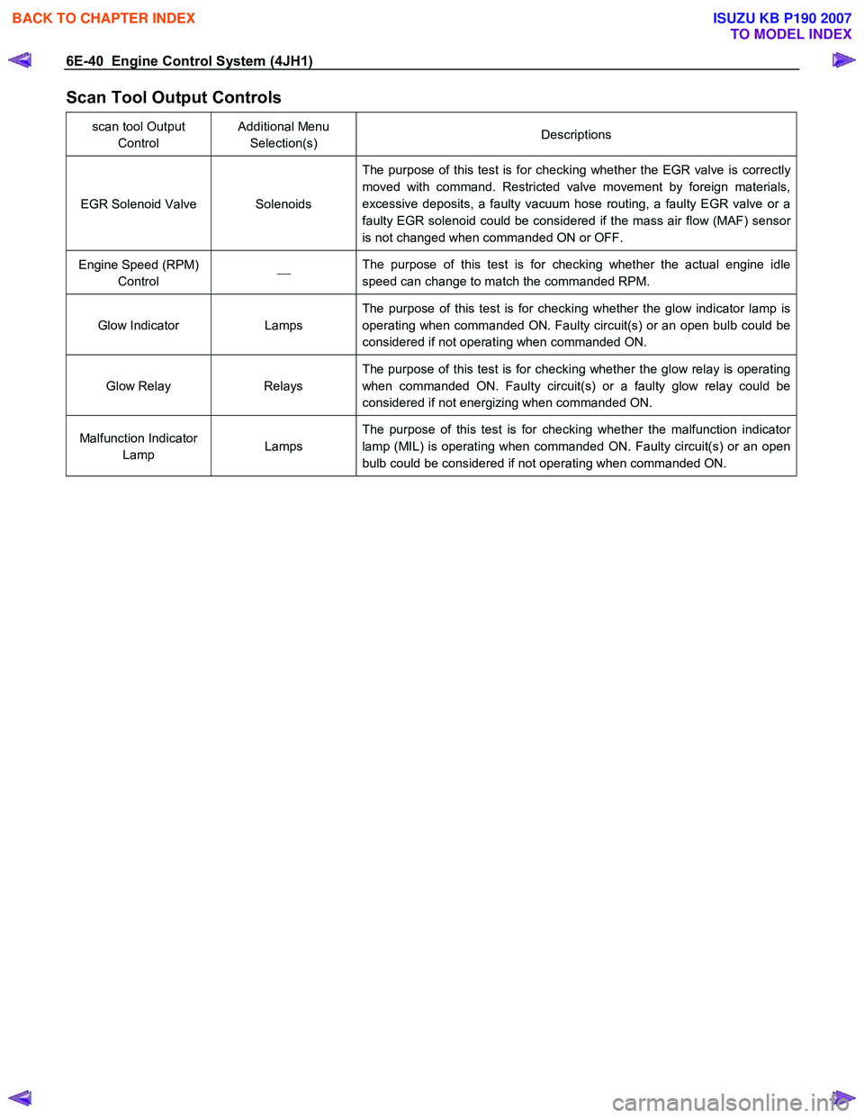
Scan Tool Output Controls
scan tool Output Control Additional Menu
Selection(s) Descriptions
EGR Solenoid Valve Solenoids The purpose of this test is for checking whether the EGR valve is correctly
moved with command. Restricted valve movement by foreign materials,
excessive deposits, a faulty vacuum hose routing, a faulty EGR valve or a
faulty EGR solenoid could be considered if the mass air flow (MAF) sensor
is not changed when commanded ON or OFF.
Engine Speed (RPM) Control
The purpose of this test is for checking whether the actual engine idle
speed can change to match the commanded RPM.
Glow Indicator Lamps The purpose of this test is for checking whether the glow indicator lamp is
operating when commanded ON. Faulty circuit(s) or an open bulb could be
considered if not operating when commanded ON.
Glow Relay Relays The purpose of this test is for checking whether the glow relay is operating
when commanded ON. Faulty circuit(s) or a faulty glow relay could be
considered if not energizing when commanded ON.
Malfunction Indicator Lamp Lamps The purpose of this test is for checking whether the malfunction indicator
lamp (MIL) is operating when commanded ON. Faulty circuit(s) or an open
bulb could be considered if not operating when commanded ON.
BACK TO CHAPTER INDEX
TO MODEL INDEX
ISUZU KB P190 2007
Page 1075 of 6020
Engine Control System (4JH1) 6E-41
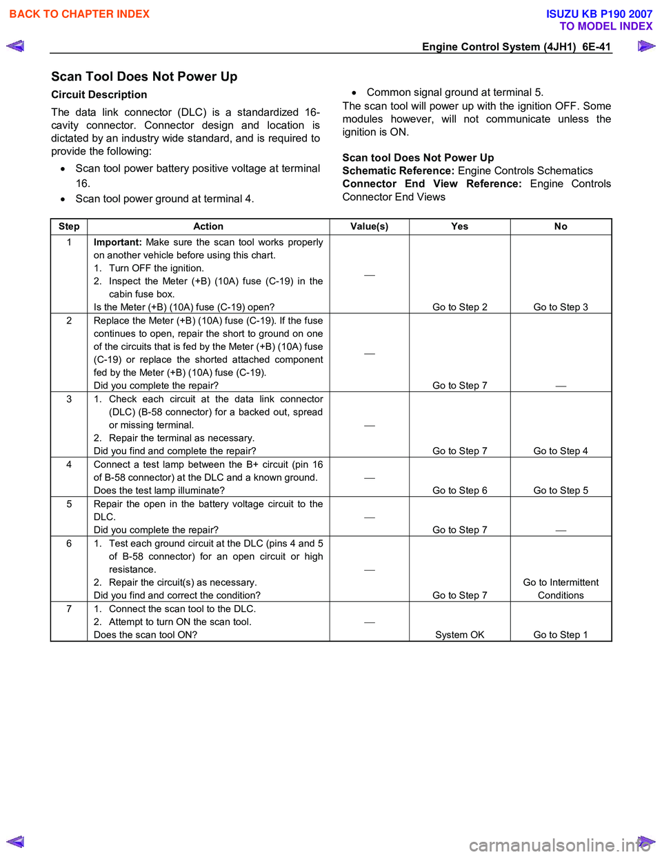
Scan Tool Does Not Power Up
Circuit Description
The data link connector (DLC) is a standardized 16-
cavity connector. Connector design and location is
dictated by an industry wide standard, and is required to
provide the following:
• Scan tool power battery positive voltage at terminal
16.
• Scan tool power ground at terminal 4.
•
Common signal ground at terminal 5.
The scan tool will power up with the ignition OFF. Some
modules however, will not communicate unless the
ignition is ON.
Scan tool Does Not Power Up
Schematic Reference: Engine Controls Schematics
Connector End View Reference: Engine Controls
Connector End Views
Step Action Value(s) Yes No
1 Important: Make sure the scan tool works properly
on another vehicle before using this chart.
1. Turn OFF the ignition.
2. Inspect the Meter (+B) (10A) fuse (C-19) in the cabin fuse box.
Is the Meter (+B) (10A) fuse (C-19) open?
Go to Step 2 Go to Step 3
2 Replace the Meter (+B) (10A) fuse (C-19). If the fuse continues to open, repair the short to ground on one
of the circuits that is fed by the Meter (+B) (10A) fuse
(C-19) or replace the shorted attached component
fed by the Meter (+B) (10A) fuse (C-19).
Did you complete the repair?
Go to Step 7
3 1. Check each circuit at the data link connector
(DLC) (B-58 connector) for a backed out, spread
or missing terminal.
2. Repair the terminal as necessary.
Did you find and complete the repair?
Go to Step 7 Go to Step 4
4 Connect a test lamp between the B+ circuit (pin 16 of B-58 connector) at the DLC and a known ground.
Does the test lamp illuminate?
Go to Step 6 Go to Step 5
5 Repair the open in the battery voltage circuit to the DLC.
Did you complete the repair?
Go to Step 7
6 1. Test each ground circuit at the DLC (pins 4 and 5
of B-58 connector) for an open circuit or high
resistance.
2. Repair the circuit(s) as necessary.
Did you find and correct the condition?
Go to Step 7 Go to Intermittent
Conditions
7 1. Connect the scan tool to the DLC. 2. Attempt to turn ON the scan tool.
Does the scan tool ON?
System OK Go to Step 1
BACK TO CHAPTER INDEX
TO MODEL INDEX
ISUZU KB P190 2007