2007 ISUZU KB P190 air condition
[x] Cancel search: air conditionPage 1308 of 6020
6E-274 Engine Control System (4JH1)
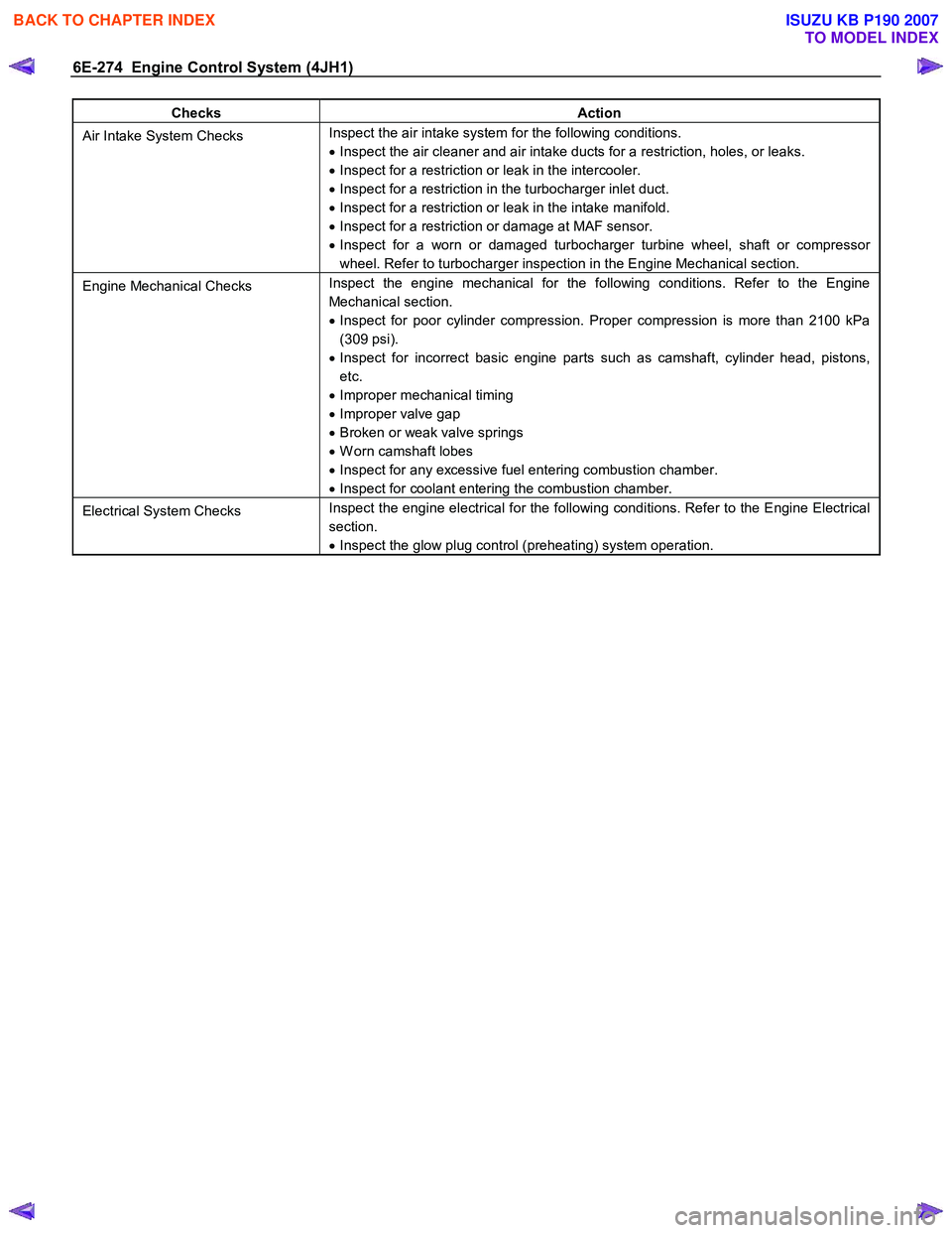
Checks Action
Air Intake System Checks Inspect the air intake system for the following conditions.
• Inspect the air cleaner and air intake ducts for a restriction, holes, or leaks.
• Inspect for a restriction or leak in the intercooler.
• Inspect for a restriction in the turbocharger inlet duct.
• Inspect for a restriction or leak in the intake manifold.
• Inspect for a restriction or damage at MAF sensor.
• Inspect for a worn or damaged turbocharger turbine wheel, shaft or compressor
wheel. Refer to turbocharger inspection in the Engine Mechanical section.
Engine Mechanical Checks Inspect the engine mechanical for the following conditions. Refer to the Engine
Mechanical section.
• Inspect for poor cylinder compression. Proper compression is more than 2100 kPa
(309 psi).
• Inspect for incorrect basic engine parts such as camshaft, cylinder head, pistons,
etc.
• Improper mechanical timing
• Improper valve gap
• Broken or weak valve springs
• W orn camshaft lobes
• Inspect for any excessive fuel entering combustion chamber.
• Inspect for coolant entering the combustion chamber.
Electrical System Checks Inspect the engine electrical for the following conditions. Refer to the Engine Electrical
section.
• Inspect the glow plug control (preheating) system operation.
BACK TO CHAPTER INDEX
TO MODEL INDEX
ISUZU KB P190 2007
Page 1310 of 6020
6E-276 Engine Control System (4JH1)
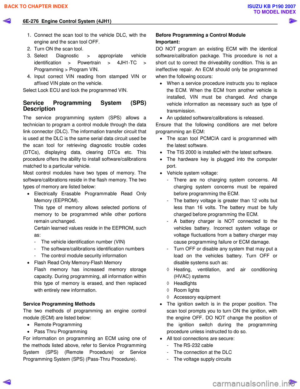
1. Connect the scan tool to the vehicle DLC, with theengine and the scan tool OFF.
2. Turn ON the scan tool.
3. Select Diagnostic > appropriate vehicle identification > Powertrain > 4JH1-TC >
Programming > Program VIN.
4. Input correct VIN reading from stamped VIN o
r
affixed VIN plate on the vehicle.
Select Lock ECU and lock the programmed VIN.
Service Programming System (SPS)
Description
The service programming system (SPS) allows a
technician to program a control module through the data
link connector (DLC). The information transfer circuit that
is used at the DLC is the same serial data circuit used be
the scan tool for retrieving diagnostic trouble codes
(DTCs), displaying data, clearing DTCs etc. This
procedure offers the ability to install software/calibrations
matched to a particular vehicle.
Most control modules have two types of memory. The
software/calibrations reside in the flash memory. The two
types of memory are listed below: • Electrically Erasable Programmable Read Onl
y
Memory (EEPROM).
This type of memory allows selected portions o
f
memory to be programmed while other portions
remain unchanged.
Certain learned values reside in the EEPROM, such as:
- The vehicle identification number (VIN)
- The software/calibrations identification numbers
- The control module security information
• Flash Read Only Memory-Flash Memory
Flash memory has increased memory storage capacity. During programming, all information within
this type of memory is erased, and then replaced
with entirely new information.
Service Programming Methods
The two methods of programming an engine control
module (ECM) are listed below: • Remote Programming
• Pass Thru Programming
For information on programming an ECM using one o
f
the methods listed above, refer to Service Programming
System (SPS) (Remote Procedure) or Service
Programming System (SPS) (Pass-Thru Procedure).
Before Programming a Control Module
Important:
DO NOT program an existing ECM with the identical
software/calibration package. This procedure is not a
short cut to correct the driveability condition. This is an
ineffective repair. An ECM should only be programmed
when the following occurs: • W hen a service procedure instructs you to replace
the ECM. W hen the ECM from another vehicle is
installed, VIN must be changed. And change
vehicle information as necessary such as type o
f
transmission.
• An updated software/calibrations is released.
Ensure that the following conditions are met before
programming an ECM: • The scan tool PCMCIA card is programmed with
the latest software.
• The TIS 2000 is installed with the latest software.
• The hardware key is plugged into the compute
r
port.
• Vehicle system voltage:
- There are no charging system concerns. All charging system concerns must be repaired
before programming the ECM.
- The battery voltage is greater than 12 volts bu
t
less than 16 volts. The battery must be fully
charged before programming the ECM.
-
A battery charger is NOT connected to the
vehicles battery. Incorrect system voltage o
r
voltage fluctuations from a battery charger may
cause programming failure or ECM damage.
- Turn OFF or disable any system that may put a load on the vehicles battery. Turn OFF o
r
disable systems such as:
◊ Heating, ventilation, and air conditioning
(HVAC) systems
◊ Headlights
◊ Room lights
◊ Accessory equipment
• The ignition switch is in the proper position. The
scan tool prompts you to turn ON the ignition, with
the engine OFF. DO NOT change the position o
f
the ignition switch during the programming
procedure unless instructed to do so.
• All tool connections are secure:
- The RS-232 cable
- The connection at the DLC
- The voltage supply circuits
BACK TO CHAPTER INDEX
TO MODEL INDEX
ISUZU KB P190 2007
Page 1320 of 6020
6E-286 Engine Control System (4JH1)
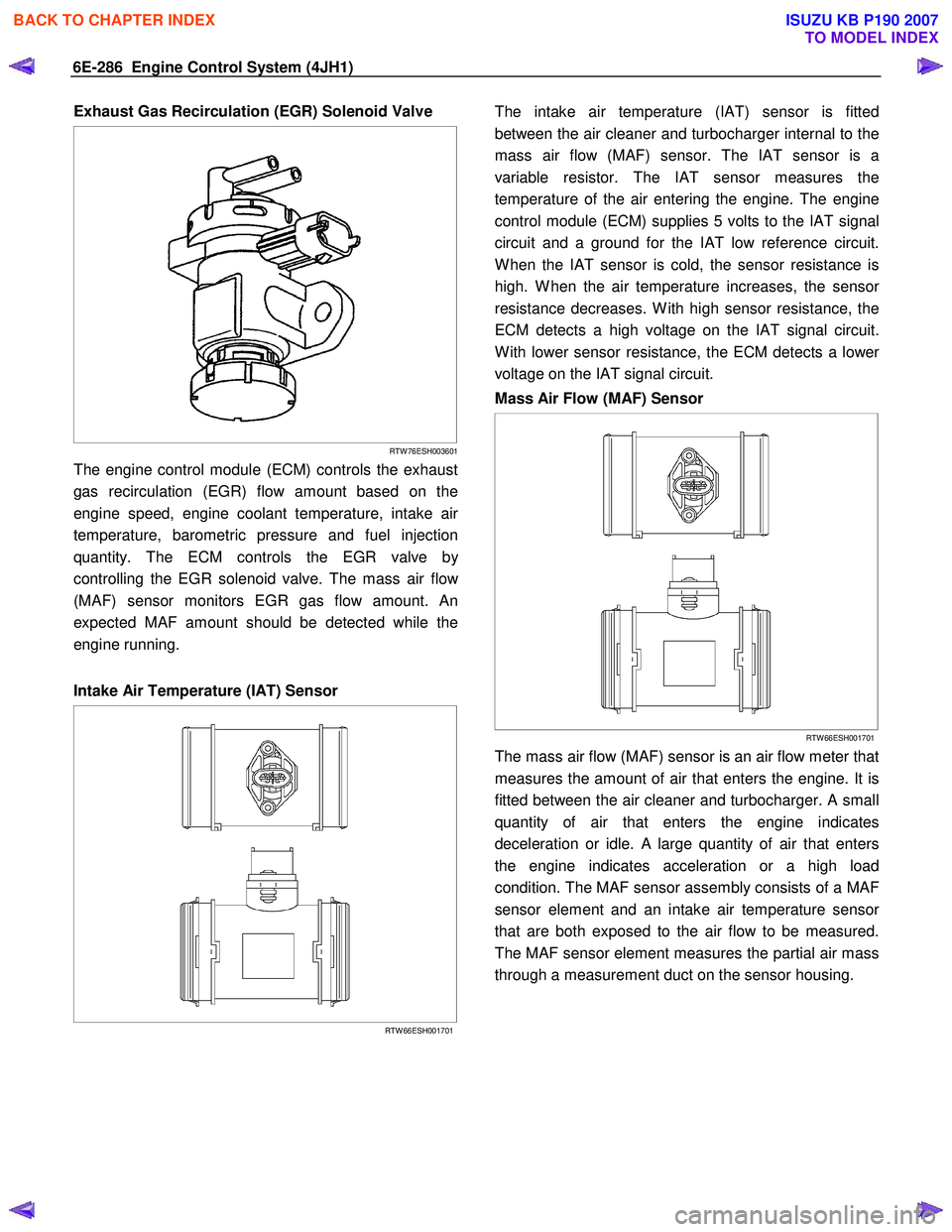
Exhaust Gas Recirculation (EGR) Solenoid Valve
RTW 76ESH003601
The engine control module (ECM) controls the exhaust
gas recirculation (EGR) flow amount based on the
engine speed, engine coolant temperature, intake ai
r
temperature, barometric pressure and fuel injection
quantity. The ECM controls the EGR valve b
y
controlling the EGR solenoid valve. The mass air flo
w
(MAF) sensor monitors EGR gas flow amount. An
expected MAF amount should be detected while the
engine running.
Intake Air Temperature (IAT) Sensor
RTW 66ESH001701
The intake air temperature (IAT) sensor is fitted
between the air cleaner and turbocharger internal to the
mass air flow (MAF) sensor. The IAT sensor is a
variable resistor. The IAT sensor measures the
temperature of the air entering the engine. The engine
control module (ECM) supplies 5 volts to the IAT signal
circuit and a ground for the IAT low reference circuit.
W hen the IAT sensor is cold, the sensor resistance is
high. W hen the air temperature increases, the senso
r
resistance decreases. W ith high sensor resistance, the
ECM detects a high voltage on the IAT signal circuit.
W ith lower sensor resistance, the ECM detects a lowe
r
voltage on the IAT signal circuit.
Mass Air Flow (MAF) Sensor
RTW 66ESH001701
The mass air flow (MAF) sensor is an air flow meter that
measures the amount of air that enters the engine. It is
fitted between the air cleaner and turbocharger. A small
quantity of air that enters the engine indicates
deceleration or idle. A large quantity of air that enters
the engine indicates acceleration or a high load
condition. The MAF sensor assembly consists of a MAF
sensor element and an intake air temperature senso
r
that are both exposed to the air flow to be measured.
The MAF sensor element measures the partial air mass
through a measurement duct on the sensor housing.
BACK TO CHAPTER INDEX
TO MODEL INDEX
ISUZU KB P190 2007
Page 1368 of 6020
6A-8 ENGINE MECHANICAL (4JK1/4JJ1)
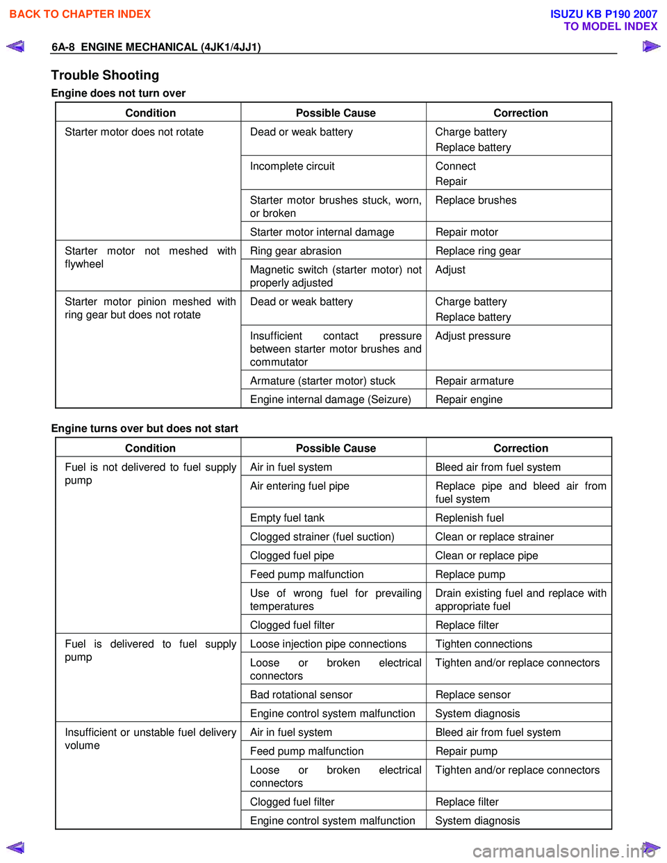
Trouble Shooting
Engine does not turn over
Condition Possible Cause Correction
Dead or weak battery Charge battery
Replace battery
Incomplete circuit Connect
Repair
Starter motor brushes stuck, worn,
or broken Replace brushes
Starter motor does not rotate
Starter motor internal damage Repair motor
Ring gear abrasion Replace ring gear Starter motor not meshed with
flywheel Magnetic switch (starter motor) not
properly adjusted Adjust
Dead or weak battery
Charge battery
Replace battery
Insufficient contact pressure
between starter motor brushes and
commutator Adjust pressure
Armature (starter motor) stuck Repair armature
Starter motor pinion meshed with
ring gear but does not rotate
Engine internal damage (Seizure) Repair engine
Engine turns over but does not start
Condition Possible Cause Correction
Air in fuel system Bleed air from fuel system
Air entering fuel pipe Replace pipe and bleed air from
fuel system
Empty fuel tank Replenish fuel
Clogged strainer (fuel suction) Clean or replace strainer
Clogged fuel pipe Clean or replace pipe
Feed pump malfunction Replace pump
Use of wrong fuel for prevailing
temperatures Drain existing fuel and replace with
appropriate fuel
Fuel is not delivered to fuel supply
pump
Clogged fuel filter Replace filter
Loose injection pipe connections Tighten connections
Loose or broken electrical
connectors Tighten and/or replace connectors
Bad rotational sensor
Replace sensor
Fuel is delivered to fuel supply
pump
Engine control system malfunction System diagnosis
Air in fuel system Bleed air from fuel system
Feed pump malfunction Repair pump
Loose or broken electrical
connectors Tighten and/or replace connectors
Clogged fuel filter
Replace filter
Insufficient or unstable fuel delivery
volume
Engine control system malfunction System diagnosis
BACK TO CHAPTER INDEX
TO MODEL INDEX
ISUZU KB P190 2007
Page 1369 of 6020

ENGINE MECHANICAL (4JK1/4JJ1) 6A-9
Excessive black exhaust smoke
Condition Possible Cause Correction
Bad injection timing Engine control system malfunction System diagnosis
Carbon deposit at nozzle tip Clean fuel injector assembly
Sticking nozzle Replace fuel injector assembly
Bad fuel injector condition
Engine control system malfunction System diagnosis
Excessive valve clearance Adjust clearance
Sticking valve stem (valve open) Repair or replace valve
Damaged valve spring Replace spring
Valve seat abrasion Repair valve seat
Compression leakage due to
damaged piston ring Replace piston ring
Damaged gasket
Replace gasket
Insufficient compression pressure
Piston scoring Replace piston
W ater in fuel Drain existing fuel and replace with
new fuel Fuel condition
Poor fuel quality Drain existing fuel and replace with
new fuel
Clogged intake pipes Clean or replace pipes Poor engine aspiration
Clogged air cleaner element Clean or replace element
Defective sensor Replace sensor Malfunction detected by engine
control system Engine control system malfunction System diagnosis
Intake throttle valve sticking Repair or replace valve
EGR valve sticking Repair or replace valve
EGR valve and/or intake throttle
valve malfunction
Engine control system malfunction System diagnosis
Damaged turbocharger blade Replace turbocharger
Rough turbocharger shaft rotation Replace turbocharger
Oil leakage from oil seal Replace turbocharger
Turbocharger malfunction
Broken actuator Replace turbocharger
BACK TO CHAPTER INDEX
TO MODEL INDEX
ISUZU KB P190 2007
Page 1370 of 6020
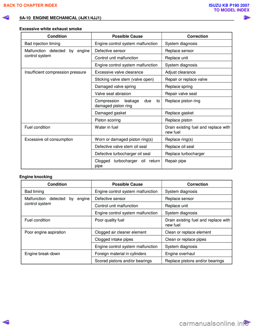
6A-10 ENGINE MECHANICAL (4JK1/4JJ1)
Excessive white exhaust smoke
Condition Possible Cause Correction
Bad injection timing Engine control system malfunction System diagnosis
Defective sensor Replace sensor
Control unit malfunction Replace unit
Malfunction detected by engine
control system
Engine control system malfunction System diagnosis
Excessive valve clearance Adjust clearance
Sticking valve stem (valve open) Repair or replace valve
Damaged valve spring Replace spring
Valve seat abrasion Repair valve seat
Compression leakage due to
damaged piston ring Replace piston ring
Damaged gasket
Replace gasket
Insufficient compression pressure
Piston scoring Replace piston
Fuel condition W ater in fuel Drain existing fuel and replace with
new fuel
W orn or damaged piston ring(s) Replace ring(s)
Defective valve stem oil seal Replace oil seal
Defective turbocharger oil seal Replace turbocharger
Excessive oil consumption
Clogged turbocharger oil return
pipe Repair pipe
Engine knocking
Condition Possible Cause Correction
Bad timing Engine control system malfunction System diagnosis
Defective sensor Replace sensor
Control unit malfunction Replace unit
Malfunction detected by engine
control system
Engine control system malfunction System diagnosis
Fuel condition Poor quality fuel Drain existing fuel and replace with
new fuel
Clogged air cleaner element Clean or replace element
Clogged intake pipes Clean or replace pipes
Poor engine aspiration
Engine control system malfunction System diagnosis
Foreign material in cylinders Engine overhaul Engine break-down Scored pistons and/or bearings Replace pistons and/or bearings
BACK TO CHAPTER INDEX
TO MODEL INDEX
ISUZU KB P190 2007
Page 1371 of 6020
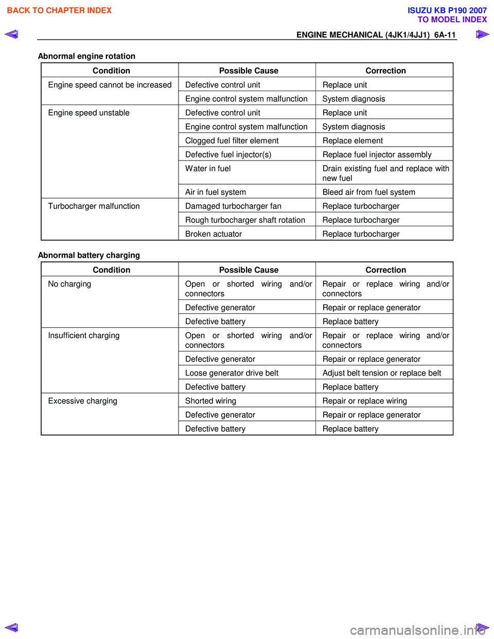
ENGINE MECHANICAL (4JK1/4JJ1) 6A-11
Abnormal engine rotation
Condition Possible Cause Correction
Defective control unit Replace unit Engine speed cannot be increased
Engine control system malfunction System diagnosis
Defective control unit Replace unit
Engine control system malfunction System diagnosis
Clogged fuel filter element Replace element
Defective fuel injector(s) Replace fuel injector assembly
W ater in fuel Drain existing fuel and replace with
new fuel
Engine speed unstable
Air in fuel system Bleed air from fuel system
Damaged turbocharger fan Replace turbocharger
Rough turbocharger shaft rotation Replace turbocharger
Turbocharger malfunction
Broken actuator Replace turbocharger
Abnormal battery charging
Condition Possible Cause Correction
Open or shorted wiring and/or
connectors Repair or replace wiring and/or
connectors
Defective generator Repair or replace generator
No charging
Defective battery Replace battery
Open or shorted wiring and/or
connectors Repair or replace wiring and/or
connectors
Defective generator Repair or replace generator
Loose generator drive belt Adjust belt tension or replace belt
Insufficient charging
Defective battery Replace battery
Shorted wiring Repair or replace wiring
Defective generator Repair or replace generator
Excessive charging
Defective battery Replace battery
BACK TO CHAPTER INDEX
TO MODEL INDEX
ISUZU KB P190 2007
Page 1372 of 6020
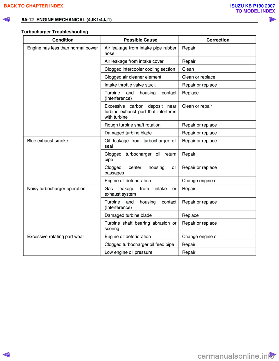
6A-12 ENGINE MECHANICAL (4JK1/4JJ1)
Turbocharger Troubleshooting
Condition Possible Cause Correction
Air leakage from intake pipe rubber
hose Repair
Air leakage from intake cover Repair
Clogged intercooler cooling section Clean
Clogged air cleaner element Clean or replace
Intake throttle valve stuck
Repair or replace
Turbine and housing contact
(Interference) Replace
Excessive carbon deposit near
turbine exhaust port that interferes
with turbine Clean or repair
Rough turbine shaft rotation Repair or replace
Engine has less than normal power
Damaged turbine blade Repair or replace
Oil leakage from turbocharger oil
seal Repair or replace
Clogged turbocharger oil return
pipe Repair
Clogged center housing oil
passages Repair or replace
Blue exhaust smoke
Engine oil deterioration Change engine oil
Gas leakage from intake or
exhaust system Repair
Turbine and housing contact
(Interference) Repair or replace
Damaged turbine blade
Replace
Noisy turbocharger operation
Turbine shaft bearing abrasion or
scoring Repair or replace
Engine oil deterioration
Change engine oil
Clogged turbocharger oil feed pipe Repair
Excessive rotating part wear
Low engine oil pressure Repair
BACK TO CHAPTER INDEX
TO MODEL INDEX
ISUZU KB P190 2007