2007 ISUZU KB P190 air condition
[x] Cancel search: air conditionPage 1417 of 6020
ENGINE MECHANICAL (4JK1/4JJ1) 6A-57
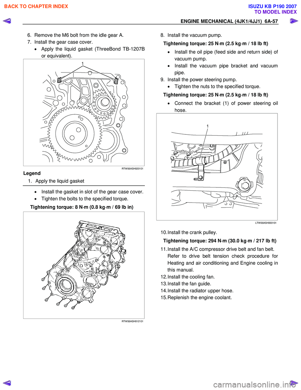
6. Remove the M6 bolt from the idle gear A.
7. Install the gear case cover. • Apply the liquid gasket (ThreeBond TB-1207B
or equivalent).
RTW 56ASH020101
Legend
1. Apply the liquid gasket
• Install the gasket in slot of the gear case cover.
• Tighten the bolts to the specified torque.
Tightening torque: 8 N ⋅
⋅⋅
⋅
m (0.8 kg ⋅
⋅⋅
⋅
m / 69 lb in)
RTW 56ASH012101
8. Install the vacuum pump.
Tightening torque: 25 N ⋅
⋅⋅
⋅
m (2.5 kg ⋅
⋅⋅
⋅
m / 18 lb ft)
• Install the oil pipe (feed side and return side) o
f
vacuum pump.
• Install the vacuum pipe bracket and vacuum
pipe.
9. Install the power steering pump. • Tighten the nuts to the specified torque.
Tightening torque: 25 N ⋅
⋅⋅
⋅
m (2.5 kg ⋅
⋅⋅
⋅
m / 18 lb ft)
• Connect the bracket (1) of power steering oil
hose.
LTW 56ASH000101
10. Install the crank pulley.
Tightening torque: 294 N ⋅
⋅⋅
⋅
m (30.0 kg ⋅
⋅⋅
⋅
m / 217 lb ft)
11. Install the A/C compressor drive belt and fan belt.
Refer to drive belt tension check procedure fo
r
Heating and air conditioning and Engine cooling in
this manual.
12. Install the cooling fan.
13. Install the fan guide.
14. Install the radiator upper hose.
15. Replenish the engine coolant.
BACK TO CHAPTER INDEX
TO MODEL INDEX
ISUZU KB P190 2007
Page 1522 of 6020
6A-162 ENGINE MECHANICAL (4JK1/4JJ1)
Removal
1. Remove the oil pressure SW .
2. Remove the nipple; oil gallery.
3. Remove the nipple; oil pressure warning SW and gasket.
Inspection
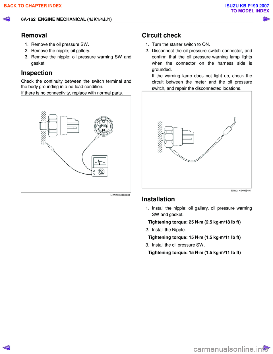
Check the continuity between the switch terminal and
the body grounding in a no-load condition.
If there is no connectivity, replace with normal parts.
LNW 21HSH003301
Circuit check
1. Turn the starter switch to ON.
2. Disconnect the oil pressure switch connector, and confirm that the oil pressure-warning lamp lights
when the connector on the harness side is
grounded.
If the warning lamp does not light up, check the circuit between the meter and the oil pressure
switch, and repair the disconnected locations.
LNW 21HSH003401
Installation
1. Install the nipple; oil gallery, oil pressure warning
SW and gasket.
Tightening torque: 25 N ⋅
⋅⋅
⋅
m (2.5 kg ⋅
⋅⋅
⋅
m/18 lb ft)
2. Install the Nipple. Tightening torque: 15 N ⋅
⋅⋅
⋅
m (1.5 kg ⋅
⋅⋅
⋅
m/11 lb ft)
3. Install the oil pressure SW . Tightening torque: 15 N ⋅
⋅⋅
⋅
m (1.5 kg ⋅
⋅⋅
⋅
m/11 lb ft)
BACK TO CHAPTER INDEX
TO MODEL INDEX
ISUZU KB P190 2007
Page 1529 of 6020
6B-6 ENGINE COOLING (4JK1/4JJ1)
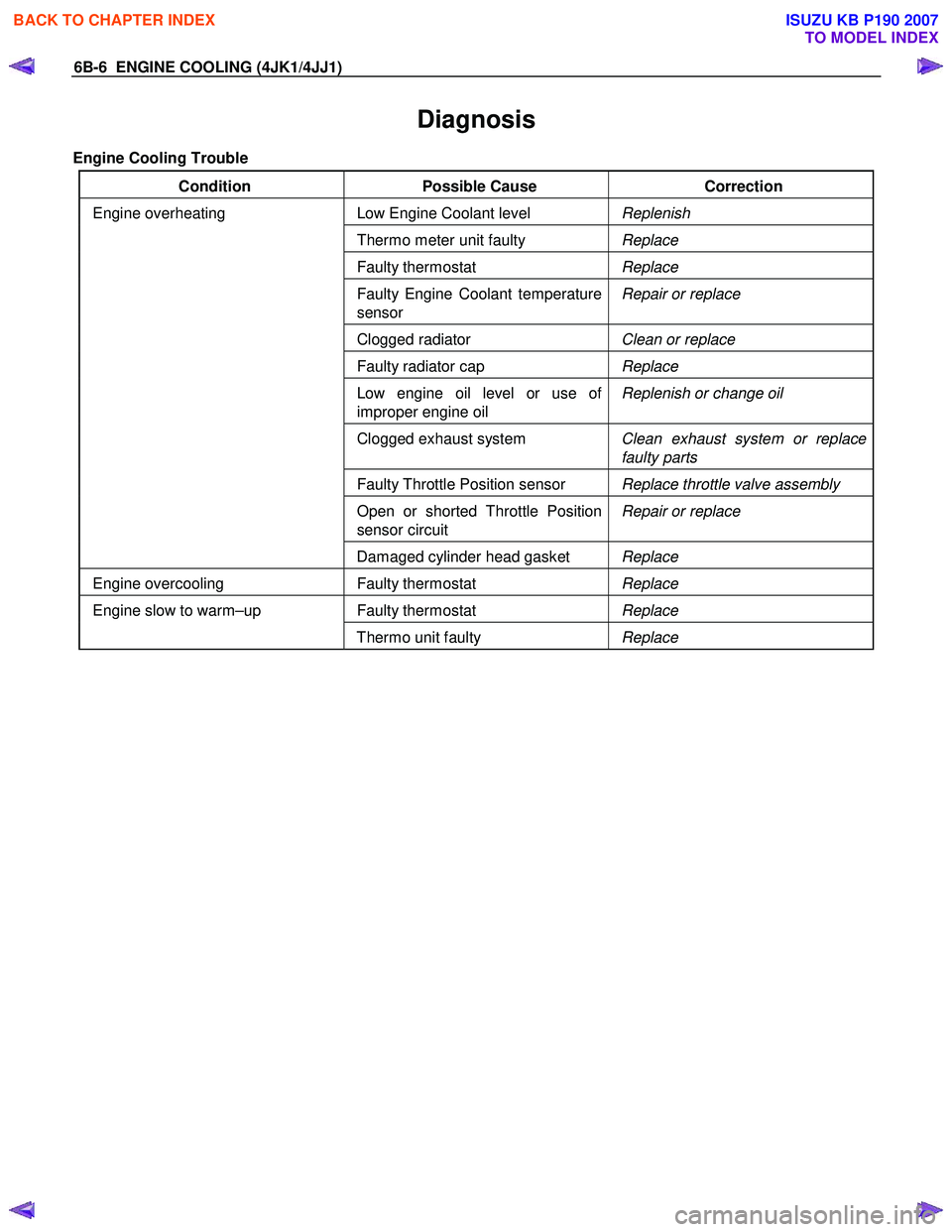
Diagnosis
Engine Cooling Trouble
Condition Possible Cause Correction
Low Engine Coolant level Replenish
Thermo meter unit faulty Replace
Faulty thermostat Replace
Faulty Engine Coolant temperature
sensor Repair or replace
Clogged radiator
Clean or replace
Faulty radiator cap Replace
Low engine oil level or use of
improper engine oil Replenish or change oil
Clogged exhaust system
Clean exhaust system or replace
faulty parts
Faulty Throttle Position sensor Replace throttle valve assembly
Open or shorted Throttle Position
sensor circuit Repair or replace
Engine overheating
Damaged cylinder head gasket Replace
Engine overcooling Faulty thermostat Replace
Faulty thermostat Replace Engine slow to warm–up
Thermo unit faulty Replace
BACK TO CHAPTER INDEX
TO MODEL INDEX
ISUZU KB P190 2007
Page 1538 of 6020
ENGINE COOLING (4JK1/4JJ1) 6B-15
Inspection and Repair
Make the necessary adjustments, repairs, and part
replacements if excessive wear or damage is
discovered during inspection.
Radiator Cap
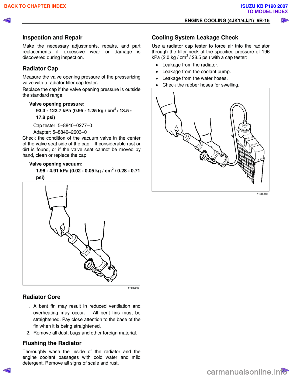
Measure the valve opening pressure of the pressurizing
valve with a radiator filler cap tester.
Replace the cap if the valve opening pressure is outside
the standard range.
Valve opening pressure: 93.3 - 122.7 kPa (0.95 - 1.25 kg / cm
2 / 13.5 -
17.8 psi)
Cap tester: 5–8840–0277–0
Adapter: 5–8840–2603–0
Check the condition of the vacuum valve in the cente
r
of the valve seat side of the cap. If considerable rust or
dirt is found, or if the valve seat cannot be moved by
hand, clean or replace the cap.
Valve opening vacuum: 1.96 - 4.91 kPa (0.02 - 0.05 kg / cm
2 / 0.28 - 0.71
psi)
110RS006
Radiator Core
1. A bent fin may result in reduced ventilation and
overheating may occur. All bent fins must be
straightened. Pay close attention to the base of the
fin when it is being straightened.
2. Remove all dust, bugs and other foreign material.
Flushing the Radiator
Thoroughly wash the inside of the radiator and the
engine coolant passages with cold water and mild
detergent. Remove all signs of scale and rust.
Cooling System Leakage Check
Use a radiator cap tester to force air into the radiator
through the filler neck at the specified pressure of 196
kPa (2.0 kg / cm2 / 28.5 psi) with a cap tester:
• Leakage from the radiator.
• Leakage from the coolant pump.
• Leakage from the water hoses.
• Check the rubber hoses for swelling.
110RS005
BACK TO CHAPTER INDEX
TO MODEL INDEX
ISUZU KB P190 2007
Page 1540 of 6020
ENGINE COOLING (4JK1/4JJ1) 6B-17
Fan Clutch with Cooling Fan
Inspection and Repair
Make necessary correction or parts replacement if
wear, damage or any other abnormal conditions are
found through inspection.
Visually inspect for damage, leak (silicon grease) o
r
other abnormal conditions.
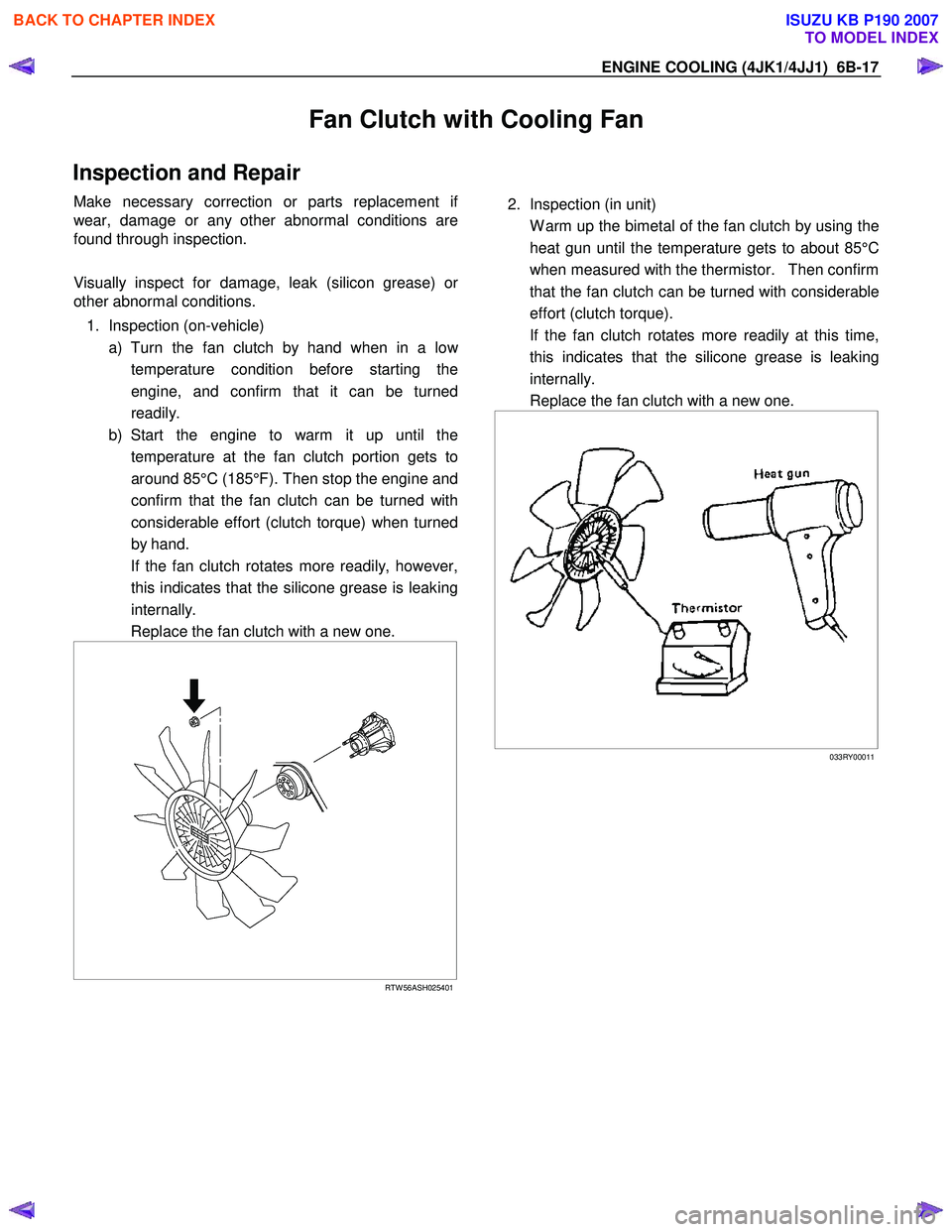
1. Inspection (on-vehicle) a) Turn the fan clutch by hand when in a lo
w
temperature condition before starting the
engine, and confirm that it can be turned
readily.
b) Start the engine to warm it up until the temperature at the fan clutch portion gets to
around 85°C (185°F). Then stop the engine and
confirm that the fan clutch can be turned with
considerable effort (clutch torque) when turned
by hand.
If the fan clutch rotates more readily, however, this indicates that the silicone grease is leaking
internally.
Replace the fan clutch with a new one.
RTW 56ASH025401
2. Inspection (in unit)
W arm up the bimetal of the fan clutch by using the heat gun until the temperature gets to about 85°C
when measured with the thermistor. Then confirm
that the fan clutch can be turned with considerable
effort (clutch torque).
If the fan clutch rotates more readily at this time, this indicates that the silicone grease is leaking
internally.
Replace the fan clutch with a new one.
033RY00011
BACK TO CHAPTER INDEX
TO MODEL INDEX
ISUZU KB P190 2007
Page 1549 of 6020
6C-8 FUEL SYSTEM (4JK1/4JJ1)
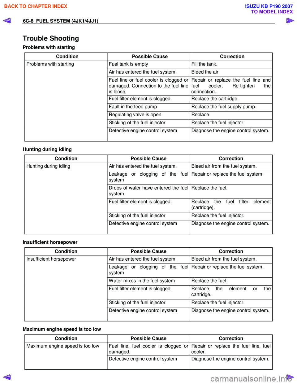
Trouble Shooting
Problems with starting
Condition Possible Cause Correction
Problems with starting Fuel tank is empty Fill the tank.
Air has entered the fuel system. Bleed the air.
Fuel line or fuel cooler is clogged or
damaged. Connection to the fuel line
is loose. Repair or replace the fuel line and
fuel cooler. Re-tighten the
connection.
Fuel filter element is clogged. Replace the cartridge.
Fault in the feed pump Replace the fuel supply pump.
Regulating valve is open. Replace
Sticking of the fuel injector Replace the fuel injector.
Defective engine control system Diagnose the engine control system.
Hunting during idling
Condition Possible Cause Correction
Hunting during idling Air has entered the fuel system. Bleed air from the fuel system.
Leakage or clogging of the fuel
system Repair or replace the fuel system.
Drops of water have entered the fuel
system. Replace the fuel.
Fuel filter element is clogged. Replace the fuel filter element
(cartridge).
Sticking of the fuel injector Replace the fuel injector.
Defective engine control system Diagnose the engine control system.
Insufficient horsepower
Condition Possible Cause Correction
Insufficient horsepower Air has entered the fuel system. Bleed air from the fuel system.
Leakage or clogging of the fuel
system Repair or replace the fuel system.
W ater mixes in the fuel system Replace the fuel.
Fuel filter element is clogged. Replace the element or the
cartridge.
Sticking of the fuel injector Replace the fuel injector.
Defective engine control system Diagnose the engine control system.
Maximum engine speed is too low
Condition Possible Cause Correction
Maximum engine speed is too low Fuel line, fuel cooler is clogged or
damaged. Repair or replace the fuel line, fuel
cooler.
Defective engine control system Diagnose the engine control system.
BACK TO CHAPTER INDEX
TO MODEL INDEX
ISUZU KB P190 2007
Page 1578 of 6020

FUEL SYSTEM (4JK1/4JJ1) 6C-37
24. Install the A/C compressor.
RTW 56ASH004201
Legend
1. A/C Compressor Bracket
2. Intake Duct
3. A/C Compressor
Tighten the bolts to the specified torque.
Tightening torque: 44 N ⋅
⋅⋅
⋅
m (4.5 kg ⋅
⋅⋅
⋅
m / 33 lb ft)
25. Install the battery.
26. Install the A/C compressor adjust pulley.
RTW 56ASH010601
Legend
1. Bolt
2. Nut
Tighten the nut and bolt to the specified torque.
Bolt Tightening torque: 25 N ⋅
⋅⋅
⋅
m (2.5 kg ⋅
⋅⋅
⋅
m/18 lb ft)
Nut Tightening torque: 25 N ⋅
⋅⋅
⋅
m (2.5 kg ⋅
⋅⋅
⋅
m/18 lb ft)
27. Install the A/C compressor drive belt.
Refer to the drive belt tension check procedure fo
r
Heating and air conditioning in this manual.
28. Install the cooling fan.
29. Install the fan guide.
30. Install the radiator upper hose.
31. Replenish the engine coolant.
Fuel Supply Pump Relearn Procedure
The ECM goes through a fuel supply pump learn
procedure to fine tune the current supplied to the fuel
rail pressure (FRP) regulator. This learning process in
only performed when the engine is idling.
1. Install the scan tool.
2. Turn ON the ignition, with the engine OFF.
3. Command the Supply Pump Learn Reset with the scan tool.
4. Observe the Supply Pump Status parameter with the scan tool. Confirm the scan tool indicates Not
Learn.
5. Start the engine and let idle until engine coolant temperature (ECT) reads 149°F (65°C) or highe
r
while observing Supply Pump Status parameter
with the scant tool. The scan tool changes status
Not Learn > Learning > Learned.
6. If the ECM has correctly learned the fuel supply pump current adjustment, the Supply Pump Status
parameter on the scan tool will repeatedly indicate
Learning and Learned.
BACK TO CHAPTER INDEX
TO MODEL INDEX
ISUZU KB P190 2007
Page 1619 of 6020
6E-2 ENGINE CONTROL SYSTEM (4JK1/4JJ1)
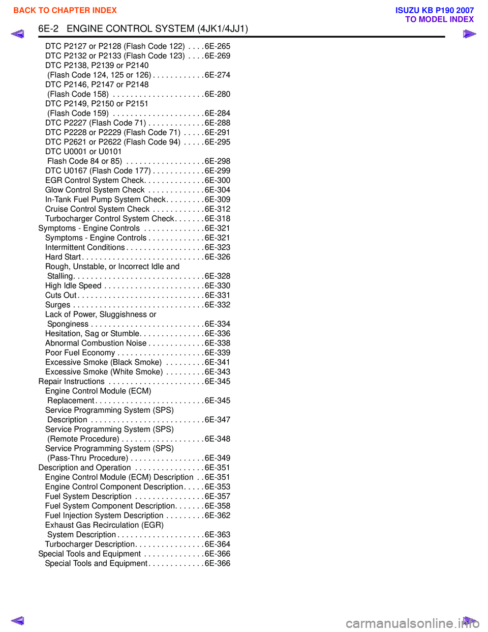
DTC P2127 or P2128 (Flash Code 122) . . . . 6E-265
DTC P2132 or P2133 (Flash Code 123) . . . . 6E-269
DTC P2138, P2139 or P2140 (Flash Code 124, 125 or 126) . . . . . . . . . . . . 6E-274
DTC P2146, P2147 or P2148 (Flash Code 158) . . . . . . . . . . . . . . . . . . . . . 6E-280
DTC P2149, P2150 or P2151 (Flash Code 159) . . . . . . . . . . . . . . . . . . . . . 6E-284
DTC P2227 (Flash Code 71) . . . . . . . . . . . . . 6E-288
DTC P2228 or P2229 (Flash Code 71) . . . . . 6E-291
DTC P2621 or P2622 (Flash Code 94) . . . . . 6E-295
DTC U0001 or U0101 Flash Code 84 or 85) . . . . . . . . . . . . . . . . . . 6E-298
DTC U0167 (Flash Code 177) . . . . . . . . . . . . 6E-299
EGR Control System Check. . . . . . . . . . . . . . 6E-300
Glow Control System Check . . . . . . . . . . . . . 6E-304
In-Tank Fuel Pump System Check . . . . . . . . . 6E-309
Cruise Control System Check . . . . . . . . . . . . 6E-312
Turbocharger Control System Check . . . . . . . 6E-318
Symptoms - Engine Controls . . . . . . . . . . . . . . 6E-321 Symptoms - Engine Controls . . . . . . . . . . . . . 6E-321
Intermittent Conditions . . . . . . . . . . . . . . . . . . 6E-323
Hard Start . . . . . . . . . . . . . . . . . . . . . . . . . . . . 6E-326
Rough, Unstable, or Incorrect Idle and Stalling. . . . . . . . . . . . . . . . . . . . . . . . . . . . . . 6E-328
High Idle Speed . . . . . . . . . . . . . . . . . . . . . . . 6E-330
Cuts Out . . . . . . . . . . . . . . . . . . . . . . . . . . . . . 6E-331
Surges . . . . . . . . . . . . . . . . . . . . . . . . . . . . . . 6E-332
Lack of Power, Sluggishness or Sponginess . . . . . . . . . . . . . . . . . . . . . . . . . . 6E-334
Hesitation, Sag or Stumble. . . . . . . . . . . . . . . 6E-336
Abnormal Combustion Noise . . . . . . . . . . . . . 6E-338
Poor Fuel Economy . . . . . . . . . . . . . . . . . . . . 6E-339
Excessive Smoke (Black Smoke) . . . . . . . . . 6E-341
Excessive Smoke (White Smoke) . . . . . . . . . 6E-343
Repair Instructions . . . . . . . . . . . . . . . . . . . . . . 6E-345 Engine Control Module (ECM) Replacement . . . . . . . . . . . . . . . . . . . . . . . . . 6E-345
Service Programming System (SPS) Description . . . . . . . . . . . . . . . . . . . . . . . . . . 6E-347
Service Programming System (SPS) (Remote Procedure) . . . . . . . . . . . . . . . . . . . 6E-348
Service Programming System (SPS) (Pass-Thru Procedure) . . . . . . . . . . . . . . . . . 6E-349
Description and Operation . . . . . . . . . . . . . . . . 6E-351 Engine Control Module (ECM) Description . . 6E-351
Engine Control Component Description . . . . . 6E-353
Fuel System Description . . . . . . . . . . . . . . . . 6E-357
Fuel System Component Description. . . . . . . 6E-358
Fuel Injection System Description . . . . . . . . . 6E-362
Exhaust Gas Recirculation (EGR) System Description . . . . . . . . . . . . . . . . . . . . 6E-363
Turbocharger Description . . . . . . . . . . . . . . . . 6E-364
Special Tools and Equipment . . . . . . . . . . . . . . 6E-366 Special Tools and Equipment . . . . . . . . . . . . . 6E-366
BACK TO CHAPTER INDEX
TO MODEL INDEX
ISUZU KB P190 2007