2007 ISUZU KB P190 air condition
[x] Cancel search: air conditionPage 1622 of 6020
ENGINE CONTROL SYSTEM (4JK1/4JJ1) 6E-5
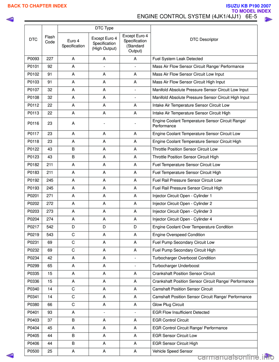
P0093 227 AAA Fuel System Leak Detected
P0101 92 A -- Mass Air Flow Sensor Circuit Range/ Performance
P0102 91 A AA Mass Air Flow Sensor Circuit Low Input
P0103 91 A AA Mass Air Flow Sensor Circuit High Input
P0107 32 A A- Manifold Absolute Pressure Sensor Circuit Low Input
P0108 32 A A- Manifold Absolute Pressure Sensor Circuit High Input
P0112 22 A AA Intake Air Temperature Sensor Circuit Low
P0113 22 A AA Intake Air Temperature Sensor Circuit High
P0116 23 A --Engine Coolant Temperature Sensor Circuit Range/
Performance
P0117 23 A AA Engine Coolant Temperature Sensor Circuit Low
P0118 23 A AA Engine Coolant Temperature Sensor Circuit High
P0122 43 B AA Throttle Position Sensor Circuit Low
P0123 43 B AA Throttle Position Sensor Circuit High
P0182 211 A AA Fuel Temperature Sensor Circuit Low
P0183 211 A AA Fuel Temperature Sensor Circuit High
P0192 245 A AA Fuel Rail Pressure Sensor Circuit Low
P0193 245 A AA Fuel Rail Pressure Sensor Circuit High
P0201 271 A AA Injector Circuit Open - Cylinder 1
P0202 272 A AA Injector Circuit Open - Cylinder 2
P0203 273 A AA Injector Circuit Open - Cylinder 3
P0204 274 A AA Injector Circuit Open - Cylinder 4
P0217 542 D DD Engine Coolant Over Temperature Condition
P0219 543 C AA Engine Overspeed Condition
P0231 69 C AA Fuel Pump Secondary Circuit Low
P0232 69 C AA Fuel Pump Secondary Circuit High
P0234 42 A A- Turbocharger Overboost Condition
P0299 65 A A- Turbocharger Underboost
P0335 15 A AA Crankshaft Position Sensor Circuit
P0336 15 A AA Crankshaft Position Sensor Circuit Range/ Performance
P0340 14 C AA Camshaft Position Sensor Circuit
P0341 14 C AA Camshaft Position Sensor Circuit Range/ Performance
P0380 66 C AA Glow Plug Circuit
P0401 93 A -- EGR Flow Insufficient Detected
P0403 37 B AA EGR Control Circuit
P0404 45 A AA EGR Control Circuit Range/ Performance
P0405 44 B AA EGR Sensor Circuit Low
P0406 44 B AA EGR Sensor Circuit High
P0500 25 A AA Vehicle Speed Sensor
DTC
Flash
Code DTC Type
DTC Descriptor
Euro 4
Specification Except Euro 4
Specification
(High Output) Except Euro 4
Specification (Standard Output)
BACK TO CHAPTER INDEX
TO MODEL INDEX
ISUZU KB P190 2007
Page 1664 of 6020
ENGINE CONTROL SYSTEM (4JK1/4JJ1) 6E-47
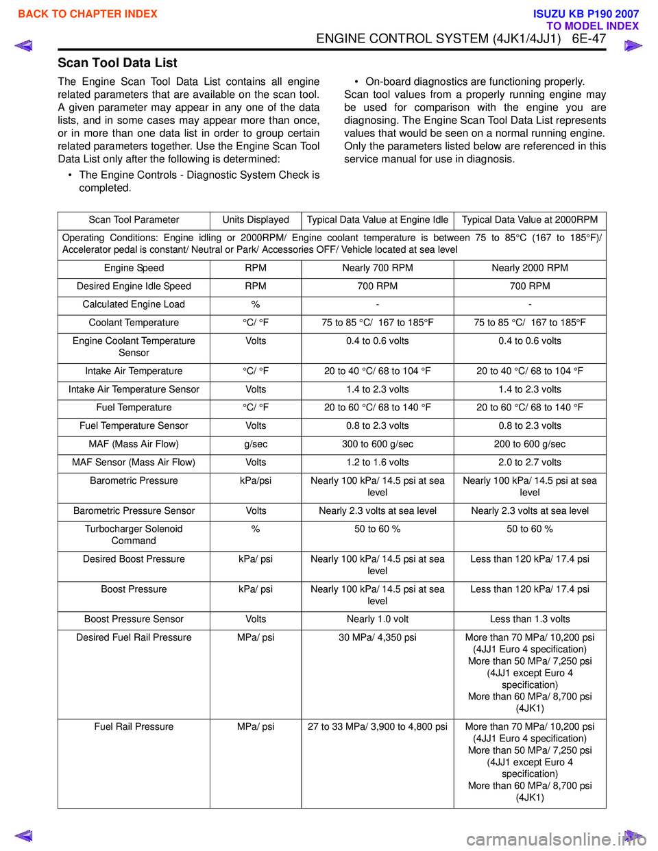
Scan Tool Data List
The Engine Scan Tool Data List contains all engine
related parameters that are available on the scan tool.
A given parameter may appear in any one of the data
lists, and in some cases may appear more than once,
or in more than one data list in order to group certain
related parameters together. Use the Engine Scan Tool
Data List only after the following is determined:
• The Engine Controls - Diagnostic System Check is completed. • On-board diagnostics are functioning properly.
Scan tool values from a properly running engine may
be used for comparison with the engine you are
diagnosing. The Engine Scan Tool Data List represents
values that would be seen on a normal running engine.
Only the parameters listed below are referenced in this
service manual for use in diagnosis.
Scan Tool Parameter Units Displayed Typical Data Value at Engine Idle Typical Data Value at 2000RPM
Operating Conditions: Engine idling or 2000RPM/ Engine coolant temperature is between 75 to 85 °C (167 to 185 °F)/
Accelerator pedal is constant/ Neutral or Park/ Accessories OFF/ Vehicle located at sea level
Engine Speed RPMNearly 700 RPM Nearly 2000 RPM
Desired Engine Idle Speed RPM700 RPM 700 RPM
Calculated Engine Load %- -
Coolant Temperature °C/ °F 75 to 85 °C/ 167 to 185 °F 75 to 85 °C/ 167 to 185 °F
Engine Coolant Temperature Sensor Volts
0.4 to 0.6 volts 0.4 to 0.6 volts
Intake Air Temperature °C/ °F 20 to 40 °C/ 68 to 104 °F 20 to 40 °C/ 68 to 104 °F
Intake Air Temperature Sensor Volts 1.4 to 2.3 volts1.4 to 2.3 volts
Fuel Temperature °C/ °F 20 to 60 °C/ 68 to 140 °F 20 to 60 °C/ 68 to 140 °F
Fuel Temperature Sensor Volts0.8 to 2.3 volts 0.8 to 2.3 volts
MAF (Mass Air Flow) g/sec300 to 600 g/sec 200 to 600 g/sec
MAF Sensor (Mass Air Flow) Volts1.2 to 1.6 volts 2.0 to 2.7 volts
Barometric Pressure kPa/psi Nearly 100 kPa/ 14.5 psi at sea
levelNearly 100 kPa/ 14.5 psi at sea
level
Barometric Pressure Sensor VoltsNearly 2.3 volts at sea level Nearly 2.3 volts at sea level
Turbocharger Solenoid Command %
50 to 60 % 50 to 60 %
Desired Boost Pressure kPa/ psi Nearly 100 kPa/ 14.5 psi at sea
levelLess than 120 kPa/ 17.4 psi
Boost Pressure kPa/ psi Nearly 100 kPa/ 14.5 psi at sea
levelLess than 120 kPa/ 17.4 psi
Boost Pressure Sensor VoltsNearly 1.0 volt Less than 1.3 volts
Desired Fuel Rail Pressure MPa/ psi 30 MPa/ 4,350 psiMore than 70 MPa/ 10,200 psi
(4JJ1 Euro 4 specification)
More than 50 MPa/ 7,250 psi
(4JJ1 except Euro 4 specification)
More than 60 MPa/ 8,700 psi
(4JK1)
Fuel Rail Pressure MPa/ psi 27 to 33 MPa/ 3,900 to 4,800 psi More than 70 MPa/ 10,200 psi
(4JJ1 Euro 4 specification)
More than 50 MPa/ 7,250 psi (4JJ1 except Euro 4 specification)
More than 60 MPa/ 8,700 psi (4JK1)
BACK TO CHAPTER INDEX
TO MODEL INDEX
ISUZU KB P190 2007
Page 1669 of 6020
6E-52 ENGINE CONTROL SYSTEM (4JK1/4JJ1)
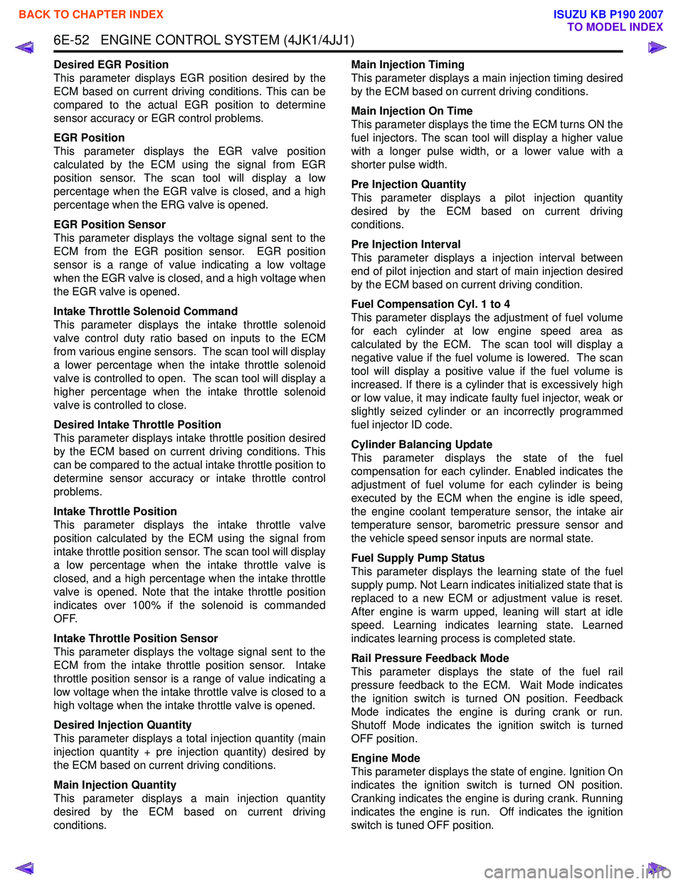
Desired EGR Position
This parameter displays EGR position desired by the
ECM based on current driving conditions. This can be
compared to the actual EGR position to determine
sensor accuracy or EGR control problems.
EGR Position
This parameter displays the EGR valve position
calculated by the ECM using the signal from EGR
position sensor. The scan tool will display a low
percentage when the EGR valve is closed, and a high
percentage when the ERG valve is opened.
EGR Position Sensor
This parameter displays the voltage signal sent to the
ECM from the EGR position sensor. EGR position
sensor is a range of value indicating a low voltage
when the EGR valve is closed, and a high voltage when
the EGR valve is opened.
Intake Throttle Solenoid Command
This parameter displays the intake throttle solenoid
valve control duty ratio based on inputs to the ECM
from various engine sensors. The scan tool will display
a lower percentage when the intake throttle solenoid
valve is controlled to open. The scan tool will display a
higher percentage when the intake throttle solenoid
valve is controlled to close.
Desired Intake Throttle Position
This parameter displays intake throttle position desired
by the ECM based on current driving conditions. This
can be compared to the actual intake throttle position to
determine sensor accuracy or intake throttle control
problems.
Intake Throttle Position
This parameter displays the intake throttle valve
position calculated by the ECM using the signal from
intake throttle position sensor. The scan tool will display
a low percentage when the intake throttle valve is
closed, and a high percentage when the intake throttle
valve is opened. Note that the intake throttle position
indicates over 100% if the solenoid is commanded
OFF.
Intake Throttle Position Sensor
This parameter displays the voltage signal sent to the
ECM from the intake throttle position sensor. Intake
throttle position sensor is a range of value indicating a
low voltage when the intake throttle valve is closed to a
high voltage when the intake throttle valve is opened.
Desired Injection Quantity
This parameter displays a total injection quantity (main
injection quantity + pre injection quantity) desired by
the ECM based on current driving conditions.
Main Injection Quantity
This parameter displays a main injection quantity
desired by the ECM based on current driving
conditions. Main Injection Timing
This parameter displays a main injection timing desired
by the ECM based on current driving conditions.
Main Injection On Time
This parameter displays the time the ECM turns ON the
fuel injectors. The scan tool will display a higher value
with a longer pulse width, or a lower value with a
shorter pulse width.
Pre Injection Quantity
This parameter displays a pilot injection quantity
desired by the ECM based on current driving
conditions.
Pre Injection Interval
This parameter displays a injection interval between
end of pilot injection and start of main injection desired
by the ECM based on current driving condition.
Fuel Compensation Cyl. 1 to 4
This parameter displays the adjustment of fuel volume
for each cylinder at low engine speed area as
calculated by the ECM. The scan tool will display a
negative value if the fuel volume is lowered. The scan
tool will display a positive value if the fuel volume is
increased. If there is a cylinder that is excessively high
or low value, it may indicate faulty fuel injector, weak or
slightly seized cylinder or an incorrectly programmed
fuel injector ID code.
Cylinder Balancing Update
This parameter displays the state of the fuel
compensation for each cylinder. Enabled indicates the
adjustment of fuel volume for each cylinder is being
executed by the ECM when the engine is idle speed,
the engine coolant temperature sensor, the intake air
temperature sensor, barometric pressure sensor and
the vehicle speed sensor inputs are normal state.
Fuel Supply Pump Status
This parameter displays the learning state of the fuel
supply pump. Not Learn indicates initialized state that is
replaced to a new ECM or adjustment value is reset.
After engine is warm upped, leaning will start at idle
speed. Learning indicates learning state. Learned
indicates learning process is completed state.
Rail Pressure Feedback Mode
This parameter displays the state of the fuel rail
pressure feedback to the ECM. Wait Mode indicates
the ignition switch is turned ON position. Feedback
Mode indicates the engine is during crank or run.
Shutoff Mode indicates the ignition switch is turned
OFF position.
Engine Mode
This parameter displays the state of engine. Ignition On
indicates the ignition switch is turned ON position.
Cranking indicates the engine is during crank. Running
indicates the engine is run. Off indicates the ignition
switch is tuned OFF position.
BACK TO CHAPTER INDEX
TO MODEL INDEX
ISUZU KB P190 2007
Page 1670 of 6020
ENGINE CONTROL SYSTEM (4JK1/4JJ1) 6E-53
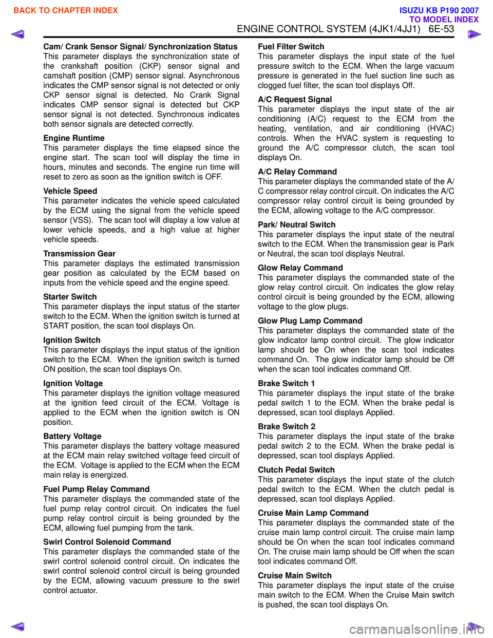
Cam/ Crank Sensor Signal/ Synchronization Status
This parameter displays the synchronization state of
the crankshaft position (CKP) sensor signal and
camshaft position (CMP) sensor signal. Asynchronous
indicates the CMP sensor signal is not detected or only
CKP sensor signal is detected. No Crank Signal
indicates CMP sensor signal is detected but CKP
sensor signal is not detected. Synchronous indicates
both sensor signals are detected correctly.
Engine Runtime
This parameter displays the time elapsed since the
engine start. The scan tool will display the time in
hours, minutes and seconds. The engine run time will
reset to zero as soon as the ignition switch is OFF.
Vehicle Speed
This parameter indicates the vehicle speed calculated
by the ECM using the signal from the vehicle speed
sensor (VSS). The scan tool will display a low value at
lower vehicle speeds, and a high value at higher
vehicle speeds.
Transmission Gear
This parameter displays the estimated transmission
gear position as calculated by the ECM based on
inputs from the vehicle speed and the engine speed.
Starter Switch
This parameter displays the input status of the starter
switch to the ECM. When the ignition switch is turned at
START position, the scan tool displays On.
Ignition Switch
This parameter displays the input status of the ignition
switch to the ECM. When the ignition switch is turned
ON position, the scan tool displays On.
Ignition Voltage
This parameter displays the ignition voltage measured
at the ignition feed circuit of the ECM. Voltage is
applied to the ECM when the ignition switch is ON
position.
Battery Voltage
This parameter displays the battery voltage measured
at the ECM main relay switched voltage feed circuit of
the ECM. Voltage is applied to the ECM when the ECM
main relay is energized.
Fuel Pump Relay Command
This parameter displays the commanded state of the
fuel pump relay control circuit. On indicates the fuel
pump relay control circuit is being grounded by the
ECM, allowing fuel pumping from the tank.
Swirl Control Solenoid Command
This parameter displays the commanded state of the
swirl control solenoid control circuit. On indicates the
swirl control solenoid control circuit is being grounded
by the ECM, allowing vacuum pressure to the swirl
control
actuator. Fuel Filter Switch
This parameter displays the input state of the fuel
pressure switch to the ECM. When the large vacuum
pressure is generated in the fuel suction line such as
clogged fuel filter, the scan tool displays Off.
A/C Request Signal
This parameter displays the input state of the air
conditioning (A/C) request to the ECM from the
heating, ventilation, and air conditioning (HVAC)
controls. When the HVAC system is requesting to
ground the A/C compressor clutch, the scan tool
displays On.
A/C Relay Command
This parameter displays the commanded state of the A/
C compressor relay control circuit. On indicates the A/C
compressor relay control circuit is being grounded by
the ECM, allowing voltage to the A/C compressor.
Park/ Neutral Switch
This parameter displays the input state of the neutral
switch to the ECM. When the transmission gear is Park
or Neutral, the scan tool displays Neutral.
Glow Relay Command
This parameter displays the commanded state of the
glow relay control circuit. On indicates the glow relay
control circuit is being grounded by the ECM, allowing
voltage to the glow plugs.
Glow Plug Lamp Command
This parameter displays the commanded state of the
glow indicator lamp control circuit. The glow indicator
lamp should be On when the scan tool indicates
command On. The glow indicator lamp should be Off
when the scan tool indicates command Off.
Brake Switch 1
This parameter displays the input state of the brake
pedal switch 1 to the ECM. When the brake pedal is
depressed, scan tool displays Applied.
Brake Switch 2
This parameter displays the input state of the brake
pedal switch 2 to the ECM. When the brake pedal is
depressed, scan tool displays Applied.
Clutch Pedal Switch
This parameter displays the input state of the clutch
pedal switch to the ECM. When the clutch pedal is
depressed, scan tool displays Applied.
Cruise Main Lamp Command
This parameter displays the commanded state of the
cruise main lamp control circuit. The cruise main lamp
should be On when the scan tool indicates command
On. The cruise main lamp should be Off when the scan
tool indicates command Off.
Cruise Main Switch
This parameter displays the input state of the cruise
main switch to the ECM. When the Cruise Main switch
is pushed, the scan tool displays On.
BACK TO CHAPTER INDEX
TO MODEL INDEX
ISUZU KB P190 2007
Page 1671 of 6020
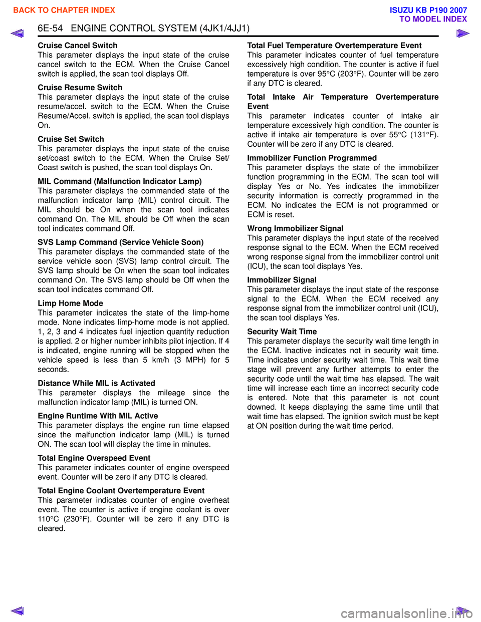
6E-54 ENGINE CONTROL SYSTEM (4JK1/4JJ1)
Cruise Cancel Switch
This parameter displays the input state of the cruise
cancel switch to the ECM. When the Cruise Cancel
switch is applied, the scan tool displays Off.
Cruise Resume Switch
This parameter displays the input state of the cruise
resume/accel. switch to the ECM. When the Cruise
Resume/Accel. switch is applied, the scan tool displays
On.
Cruise Set Switch
This parameter displays the input state of the cruise
set/coast switch to the ECM. When the Cruise Set/
Coast switch is pushed, the scan tool displays On.
MIL Command (Malfunction Indicator Lamp)
This parameter displays the commanded state of the
malfunction indicator lamp (MIL) control circuit. The
MIL should be On when the scan tool indicates
command On. The MIL should be Off when the scan
tool indicates command Off.
SVS Lamp Command (Service Vehicle Soon)
This parameter displays the commanded state of the
service vehicle soon (SVS) lamp control circuit. The
SVS lamp should be On when the scan tool indicates
command On. The SVS lamp should be Off when the
scan tool indicates command Off.
Limp Home Mode
This parameter indicates the state of the limp-home
mode. None indicates limp-home mode is not applied.
1, 2, 3 and 4 indicates fuel injection quantity reduction
is applied. 2 or higher number inhibits pilot injection. If 4
is indicated, engine running will be stopped when the
vehicle speed is less than 5 km/h (3 MPH) for 5
seconds.
Distance While MIL is Activated
This parameter displays the mileage since the
malfunction indicator lamp (MIL) is turned ON.
Engine Runtime With MIL Active
This parameter displays the engine run time elapsed
since the malfunction indicator lamp (MIL) is turned
ON. The scan tool will display the time in minutes.
Total Engine Overspeed Event
This parameter indicates counter of engine overspeed
event. Counter will be zero if any DTC is cleared.
Total Engine Coolant Overtemperature Event
This parameter indicates counter of engine overheat
event. The counter is active if engine coolant is over
11 0 °C (230 °F). Counter will be zero if any DTC is
cleared. Total Fuel Temperature Overtemperature Event
This parameter indicates counter of fuel temperature
excessively high condition. The counter is active if fuel
temperature is over 95 °C (203 °F). Counter will be zero
if any DTC is cleared.
Total Intake Air Temperature Overtemperature
Event
This parameter indicates counter of intake air
temperature excessively high condition. The counter is
active if intake air temperature is over 55 °C (131 °F).
Counter will be zero if any DTC is cleared.
Immobilizer Function Programmed
This parameter displays the state of the immobilizer
function programming in the ECM. The scan tool will
display Yes or No. Yes indicates the immobilizer
security information is correctly programmed in the
ECM. No indicates the ECM is not programmed or
ECM is reset.
Wrong Immobilizer Signal
This parameter displays the input state of the received
response signal to the ECM. When the ECM received
wrong response signal from the immobilizer control unit
(ICU), the scan tool displays Yes.
Immobilizer Signal
This parameter displays the input state of the response
signal to the ECM. When the ECM received any
response signal from the immobilizer control unit (ICU),
the scan tool displays Yes.
Security Wait Time
This parameter displays the security wait time length in
the ECM. Inactive indicates not in security wait time.
Time indicates under security wait time. This wait time
stage will prevent any further attempts to enter the
security code until the wait time has elapsed. The wait
time will increase each time an incorrect security code
is entered. Note that this parameter is not count
downed. It keeps displaying the same time until that
wait time has elapsed. The ignition switch must be kept
at ON position during the wait time period.
BACK TO CHAPTER INDEX
TO MODEL INDEX
ISUZU KB P190 2007
Page 1673 of 6020
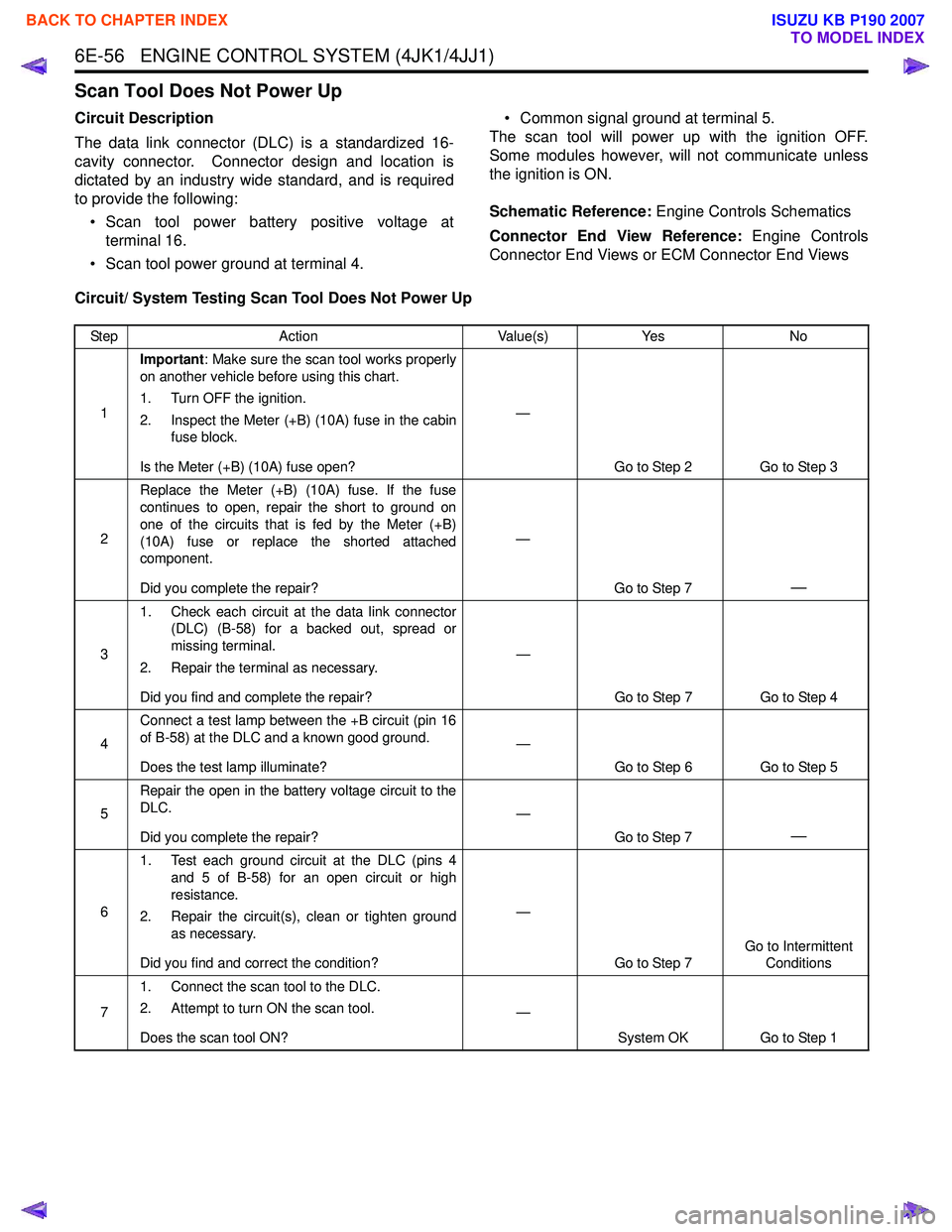
6E-56 ENGINE CONTROL SYSTEM (4JK1/4JJ1)
Scan Tool Does Not Power Up
Circuit Description
The data link connector (DLC) is a standardized 16-
cavity connector. Connector design and location is
dictated by an industry wide standard, and is required
to provide the following:
• Scan tool power battery positive voltage at terminal 16.
• Scan tool power ground at terminal 4. • Common signal ground at terminal 5.
The scan tool will power up with the ignition OFF.
Some modules however, will not communicate unless
the ignition is ON.
Schematic Reference: Engine Controls Schematics
Connector End View Reference: Engine Controls
Connector End Views or ECM Connector End Views
Circuit/ System Testing Scan Tool Does Not Power Up
Step Action Value(s)Yes No
1 Important
: Make sure the scan tool works properly
on another vehicle before using this chart.
1. Turn OFF the ignition.
2. Inspect the Meter (+B) (10A) fuse in the cabin fuse block.
Is the Meter (+B) (10A) fuse open? —
Go to Step 2 Go to Step 3
2 Replace the Meter (+B) (10A) fuse. If the fuse
continues to open, repair the short to ground on
one of the circuits that is fed by the Meter (+B)
(10A) fuse or replace the shorted attached
component.
Did you complete the repair? —
Go to Step 7
—
31. Check each circuit at the data link connector
(DLC) (B-58) for a backed out, spread or
missing terminal.
2. Repair the terminal as necessary.
Did you find and complete the repair? —
Go to Step 7 Go to Step 4
4 Connect a test lamp between the +B circuit (pin 16
of B-58) at the DLC and a known good ground.
Does the test lamp illuminate? —
Go to Step 6 Go to Step 5
5 Repair the open in the battery voltage circuit to the
DLC.
Did you complete the repair? —
Go to Step 7
—
61. Test each ground circuit at the DLC (pins 4
and 5 of B-58) for an open circuit or high
resistance.
2. Repair the circuit(s), clean or tighten ground as necessary.
Did you find and correct the condition? —
Go to Step 7 Go to Intermittent
Conditions
7 1. Connect the scan tool to the DLC.
2. Attempt to turn ON the scan tool.
Does the scan tool ON? —
System OK Go to Step 1
BACK TO CHAPTER INDEX
TO MODEL INDEX
ISUZU KB P190 2007
Page 1675 of 6020
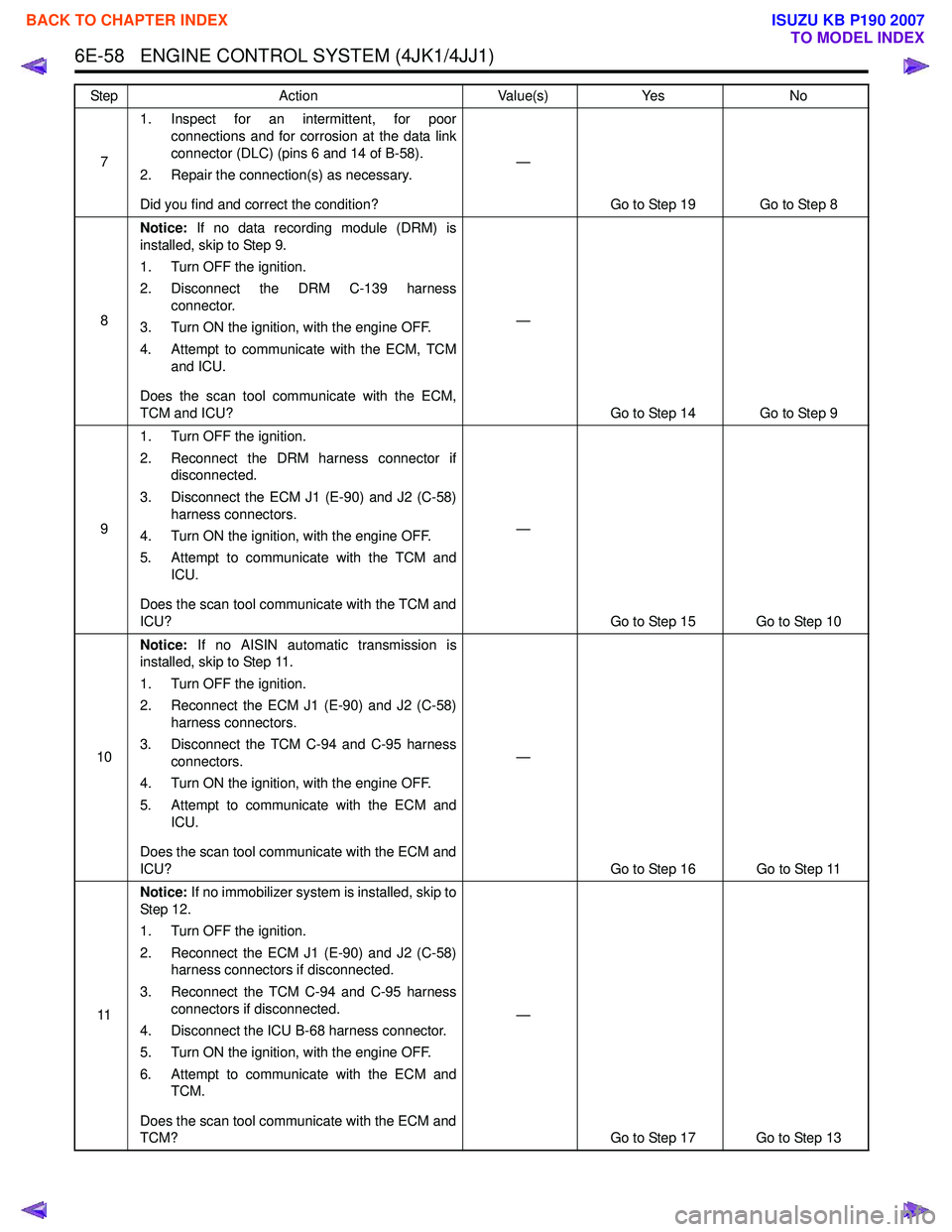
6E-58 ENGINE CONTROL SYSTEM (4JK1/4JJ1)
71. Inspect for an intermittent, for poor
connections and for corrosion at the data link
connector (DLC) (pins 6 and 14 of B-58).
2. Repair the connection(s) as necessary.
Did you find and correct the condition? —
Go to Step 19 Go to Step 8
8 Notice:
If no data recording module (DRM) is
installed, skip to Step 9.
1. Turn OFF the ignition.
2. Disconnect the DRM C-139 harness connector.
3. Turn ON the ignition, with the engine OFF.
4. Attempt to communicate with the ECM, TCM and ICU.
Does the scan tool communicate with the ECM,
TCM and ICU? —
Go to Step 14 Go to Step 9
9 1. Turn OFF the ignition.
2. Reconnect the DRM harness connector if disconnected.
3. Disconnect the ECM J1 (E-90) and J2 (C-58) harness connectors.
4. Turn ON the ignition, with the engine OFF.
5. Attempt to communicate with the TCM and ICU.
Does the scan tool communicate with the TCM and
ICU? —
Go to Step 15 Go to Step 10
10 Notice:
If no AISIN automatic transmission is
installed, skip to Step 11.
1. Turn OFF the ignition.
2. Reconnect the ECM J1 (E-90) and J2 (C-58) harness connectors.
3. Disconnect the TCM C-94 and C-95 harness connectors.
4. Turn ON the ignition, with the engine OFF.
5. Attempt to communicate with the ECM and ICU.
Does the scan tool communicate with the ECM and
ICU? —
Go to Step 16 Go to Step 11
11 Notice:
If no immobilizer system is installed, skip to
St ep 1 2.
1. Turn OFF the ignition.
2. Reconnect the ECM J1 (E-90) and J2 (C-58) harness connectors if disconnected.
3. Reconnect the TCM C-94 and C-95 harness connectors if disconnected.
4. Disconnect the ICU B-68 harness connector.
5. Turn ON the ignition, with the engine OFF.
6. Attempt to communicate with the ECM and TCM.
Does the scan tool communicate with the ECM and
TCM? —
Go to Step 17 Go to Step 13
Step
Action Value(s)Yes No
BACK TO CHAPTER INDEX
TO MODEL INDEX
ISUZU KB P190 2007
Page 1677 of 6020
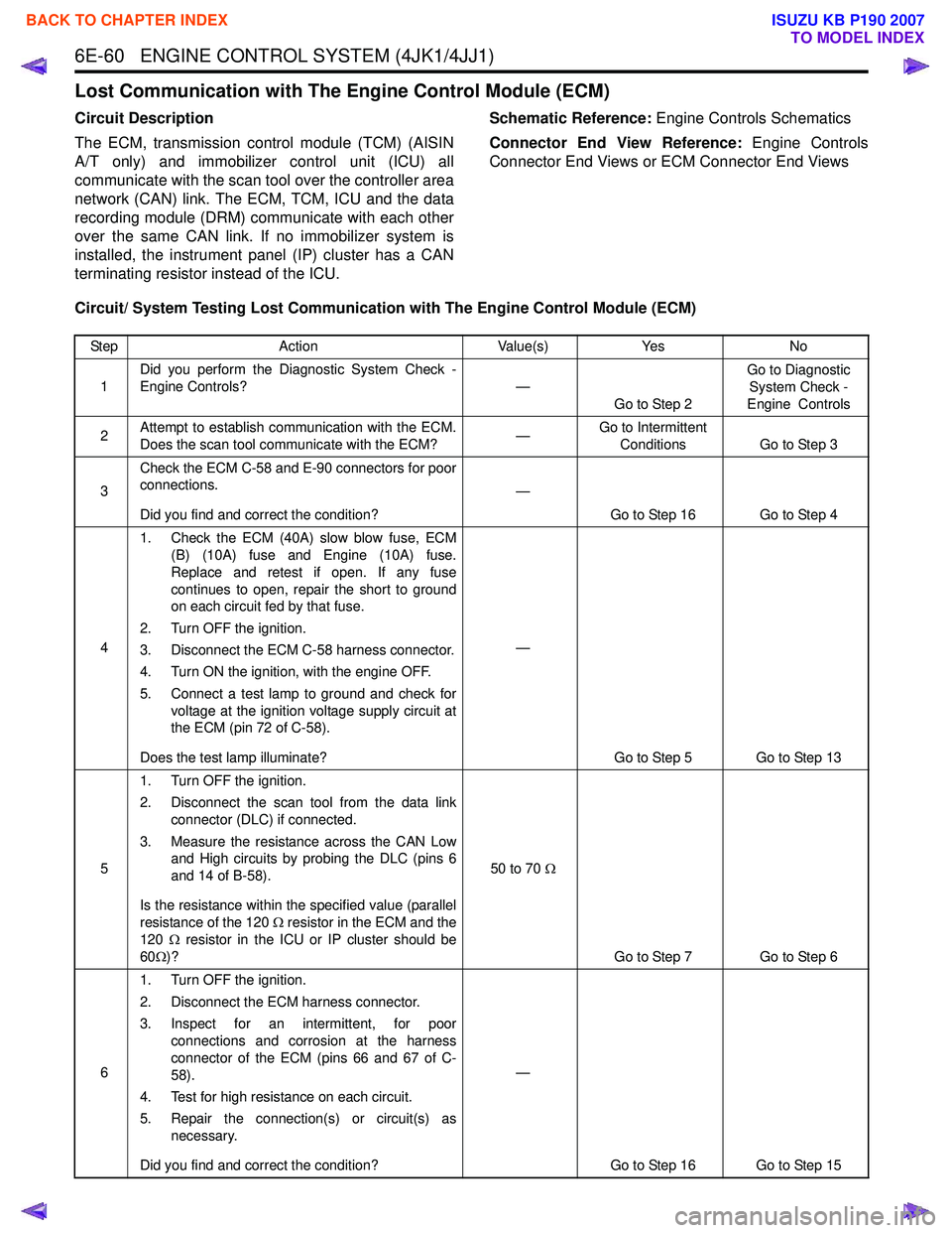
6E-60 ENGINE CONTROL SYSTEM (4JK1/4JJ1)
Lost Communication with The Engine Control Module (ECM)
Circuit Description
The ECM, transmission control module (TCM) (AISIN
A/T only) and immobilizer control unit (ICU) all
communicate with the scan tool over the controller area
network (CAN) link. The ECM, TCM, ICU and the data
recording module (DRM) communicate with each other
over the same CAN link. If no immobilizer system is
installed, the instrument panel (IP) cluster has a CAN
terminating resistor instead of the ICU. Schematic Reference:
Engine Controls Schematics
Connector End View Reference: Engine Controls
Connector End Views or ECM Connector End Views
Circuit/ System Testing Lost Communication with The Engine Control Module (ECM)
Step Action Value(s)Yes No
1 Did you perform the Diagnostic System Check -
Engine Controls? —
Go to Step 2 Go to Diagnostic
System Check -
Engine Controls
2 Attempt to establish communication with the ECM.
Does the scan tool communicate with the ECM? —Go to Intermittent
Conditions Go to Step 3
3 Check the ECM C-58 and E-90 connectors for poor
connections.
Did you find and correct the condition? —
Go to Step 16 Go to Step 4
4 1. Check the ECM (40A) slow blow fuse, ECM
(B) (10A) fuse and Engine (10A) fuse.
Replace and retest if open. If any fuse
continues to open, repair the short to ground
on each circuit fed by that fuse.
2. Turn OFF the ignition.
3. Disconnect the ECM C-58 harness connector.
4. Turn ON the ignition, with the engine OFF.
5. Connect a test lamp to ground and check for voltage at the ignition voltage supply circuit at
the ECM (pin 72 of C-58).
Does the test lamp illuminate? —
Go to Step 5 Go to Step 13
5 1. Turn OFF the ignition.
2. Disconnect the scan tool from the data link connector (DLC) if connected.
3. Measure the resistance across the CAN Low and High circuits by probing the DLC (pins 6
and 14 of B-58).
Is the resistance within the specified value (parallel
resistance of the 120 Ω resistor in the ECM and the
120 Ω resistor in the ICU or IP cluster should be
60 Ω)? 50 to 70
Ω
Go to Step 7 Go to Step 6
6 1. Turn OFF the ignition.
2. Disconnect the ECM harness connector.
3. Inspect for an intermittent, for poor connections and corrosion at the harness
connector of the ECM (pins 66 and 67 of C-
58).
4. Test for high resistance on each circuit.
5. Repair the connection(s) or circuit(s) as necessary.
Did you find and correct the condition? —
Go to Step 16 Go to Step 15
BACK TO CHAPTER INDEX
TO MODEL INDEX
ISUZU KB P190 2007