2007 ISUZU KB P190 set clock
[x] Cancel search: set clockPage 2946 of 6020
Engine Mechanical – V6 Page 6A1–169
Page 6A1–169
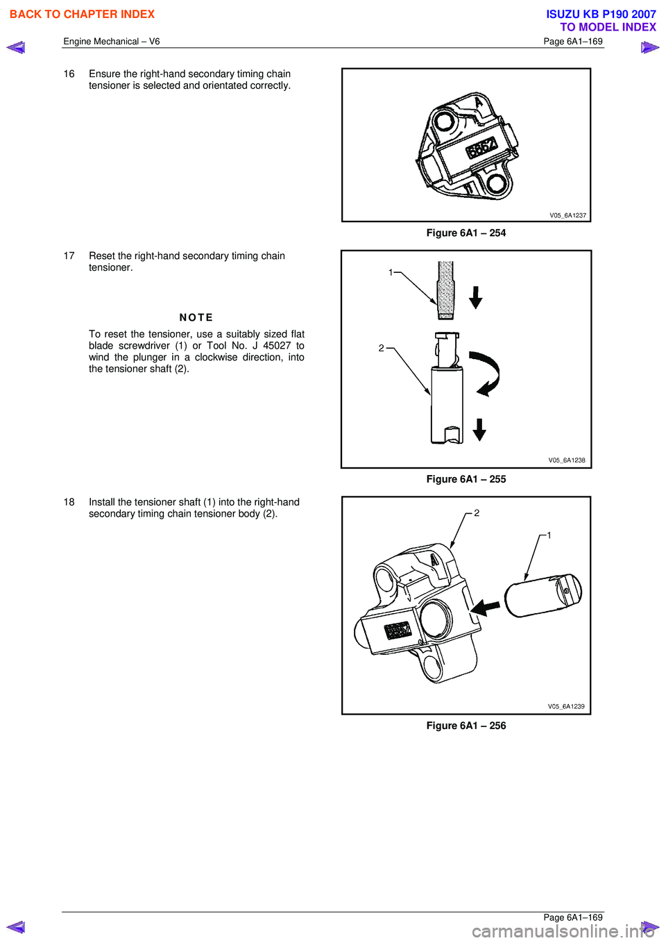
16 Ensure the right-hand secondary timing chain
tensioner is selected and orientated correctly.
Figure 6A1 – 254
17 Reset the right-hand secondary timing chain tensioner.
NOTE
To reset the tensioner, use a suitably sized flat
blade screwdriver (1) or Tool No. J 45027 to
wind the plunger in a clockwise direction, into
the tensioner shaft (2).
Figure 6A1 – 255
18 Install the tensioner s haft (1) into the right-hand
secondary timing chain tensioner body (2).
Figure 6A1 – 256
BACK TO CHAPTER INDEX
TO MODEL INDEX
ISUZU KB P190 2007
Page 2954 of 6020
Engine Mechanical – V6 Page 6A1–177
Page 6A1–177
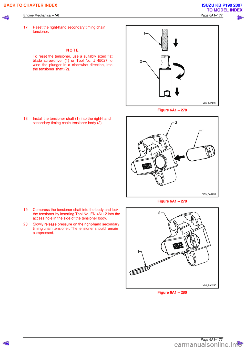
17 Reset the right-hand secondary timing chain
tensioner.
NOTE
To reset the tensioner, use a suitably sized flat
blade screwdriver (1) or Tool No. J 45027 to
wind the plunger in a clockwise direction, into
the tensioner shaft (2).
Figure 6A1 – 278
18 Install the tensioner s haft (1) into the right-hand
secondary timing chain tensioner body (2).
Figure 6A1 – 279
19 Compress the tensioner shaft into the body and lock the tensioner by inserting Tool No. EN 46112 into the
access hole in the side of the tensioner body.
20 Slowly release pressure on the right-hand secondary timing chain tensioner. The tensioner should remain
compressed.
Figure 6A1 – 280
BACK TO CHAPTER INDEX
TO MODEL INDEX
ISUZU KB P190 2007
Page 3606 of 6020
Charging System – V6 Page 6D1-1-19
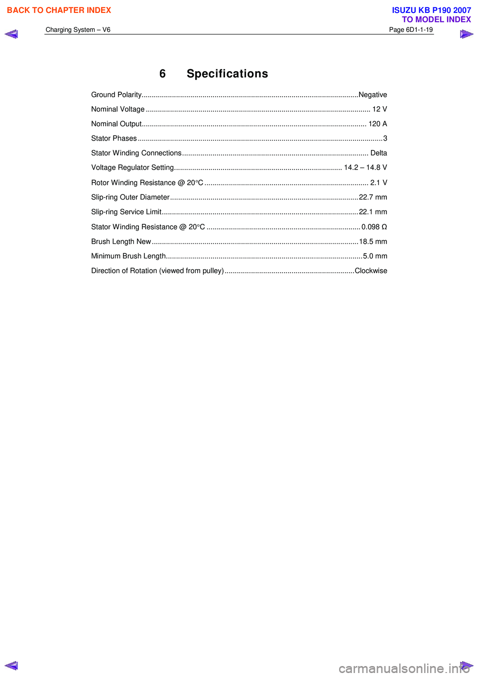
6 Specifications
Ground Polarity...........................................................................................................Negative
Nominal Voltage ............................................................................................................... 1 2 V
Nominal Output............................................................................................................... 12 0 A
Stator Phases .................................................................................................................. ....... 3
Stator W inding Connections ............................................................................................ Delta
Voltage Regulator Setting................................................................................... 14.2 – 14.8 V
Rotor W inding Resistance @ 20 °C ................................................................................. 2.1 V
Slip-ring Outer Diameter ............................................................................................. 22.7 mm
Slip-ring Service Limit ................................................................................................. 22.1 mm
Stator W inding Resistance @ 20 °C ............................................................................ 0.098 Ω
Brush Length New ...................................................................................................... 18.5 mm
Minimum Brush Length................................................................................................. 5.0 mm
Direction of Rotation (viewed from pulley) ................................................................Clockwise
BACK TO CHAPTER INDEX
TO MODEL INDEX
ISUZU KB P190 2007
Page 4275 of 6020
7A1-36 CONSTRUCTION AND FUNCTION
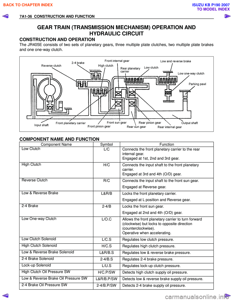
GEAR TRAIN (TRANSMISSION MECHANISM) OPERATION AND
HYDRAULIC CIRCUIT
CONSTRUCTION AND OPERATION
The JR405E consists of two sets of planetary gears, three multiple plate clutches, two multiple plate brakes
and one one-way clutch.
COMPONENT NAME AND FUNCTION
Component Name Symbol Function
Low Clutch L/C Connects the front planetary carrier to the rear
internal gear.
Engaged at 1st, 2nd and 3rd gear.
High Clutch H/C Connects the input shaft to the front planetary
carrier.
Engaged at 3rd and 4th (O/D) gear.
Reverse Clutch R/C Connects the input shaft to the front sun gear.
Engaged at Reverse gear.
Low & Reverse Brake L&R/B Locks the front planetary carrier.
Engaged at L position and Reverse gear.
2-4 Brake 2-4/B Locks the front sun gear.
Engaged at 2nd and 4th (O/D) gear.
Low One-way Clutch L/O.C Allows the front planetary carrier to turn forward
(clockwise) but locks to opposite direction
(counterclockwise).
Operative when accelerating.
Low Clutch Solenoid L/C.S Regulates low clutch pressure.
High Clutch Solenoid H/C.S Regulates high clutch pressure.
Low & Reverse Brake Solenoid L&R/B.S Regulates low & reverse brake pressure.
2-4 Brake Solenoid 2-4/B.S Regulates 2-4 brake pressure.
Lock-up Solenoid L/U.S Regulates lock-up clutch pressure.
High Clutch Oil Pressure SW H/C.P/SW Detects high clutch supply oil pressure.
Low & Reverse Brake Oil Pressure SW L&R/B.P/SWDetects low & reverse brake supply oil pressure.
2-4 Brake Oil Pressure SW 2-4/B.P/SWDetects 2-4 brake supply oil pressure.
BACK TO CHAPTER INDEX
TO MODEL INDEX
ISUZU KB P190 2007
Page 4431 of 6020
TRANSMISSION CONTROL SYSTEM (JR405E) 7A2-147
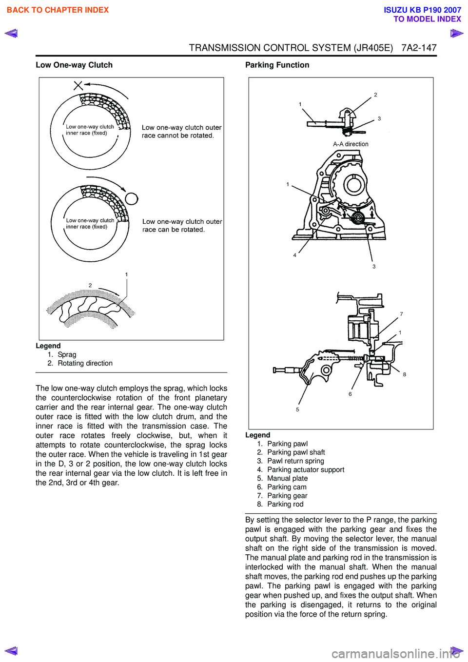
Low One-way Clutch
Legend1. Sprag
2. Rotating direction
The low one-way clutch employs the sprag, which locks
the counterclockwise rotation of the front planetary
carrier and the rear internal gear. The one-way clutch
outer race is fitted with the low clutch drum, and the
inner race is fitted with the transmission case. The
outer race rotates freely clockwise, but, when it
attempts to rotate counterclockwise, the sprag locks
the outer race. When the vehicle is traveling in 1st gear
in the D, 3 or 2 position, the low one-way clutch locks
the rear internal gear via the low clutch. It is left free in
the 2nd, 3rd or 4th gear. Parking Function
Legend
1. Parking pawl
2. Parking pawl shaft
3. Pawl return spring
4. Parking actuator support
5. Manual plate
6. Parking cam
7. Parking gear
8. Parking rod
By setting the selector lever to the P range, the parking
pawl is engaged with the parking gear and fixes the
output shaft. By moving the selector lever, the manual
shaft on the right side of the transmission is moved.
The manual plate and parking rod in the transmission is
interlocked with the manual shaft. When the manual
shaft moves, the parking rod end pushes up the parking
pawl. The parking pawl is engaged with the parking
gear when pushed up, and fixes the output shaft. When
the parking is disengaged, it returns to the original
position via the force of the return spring.
BACK TO CHAPTER INDEX
TO MODEL INDEX
ISUZU KB P190 2007
Page 4445 of 6020
TRANSMISSION CONTROL SYSTEM (JR405E) 7A2-161
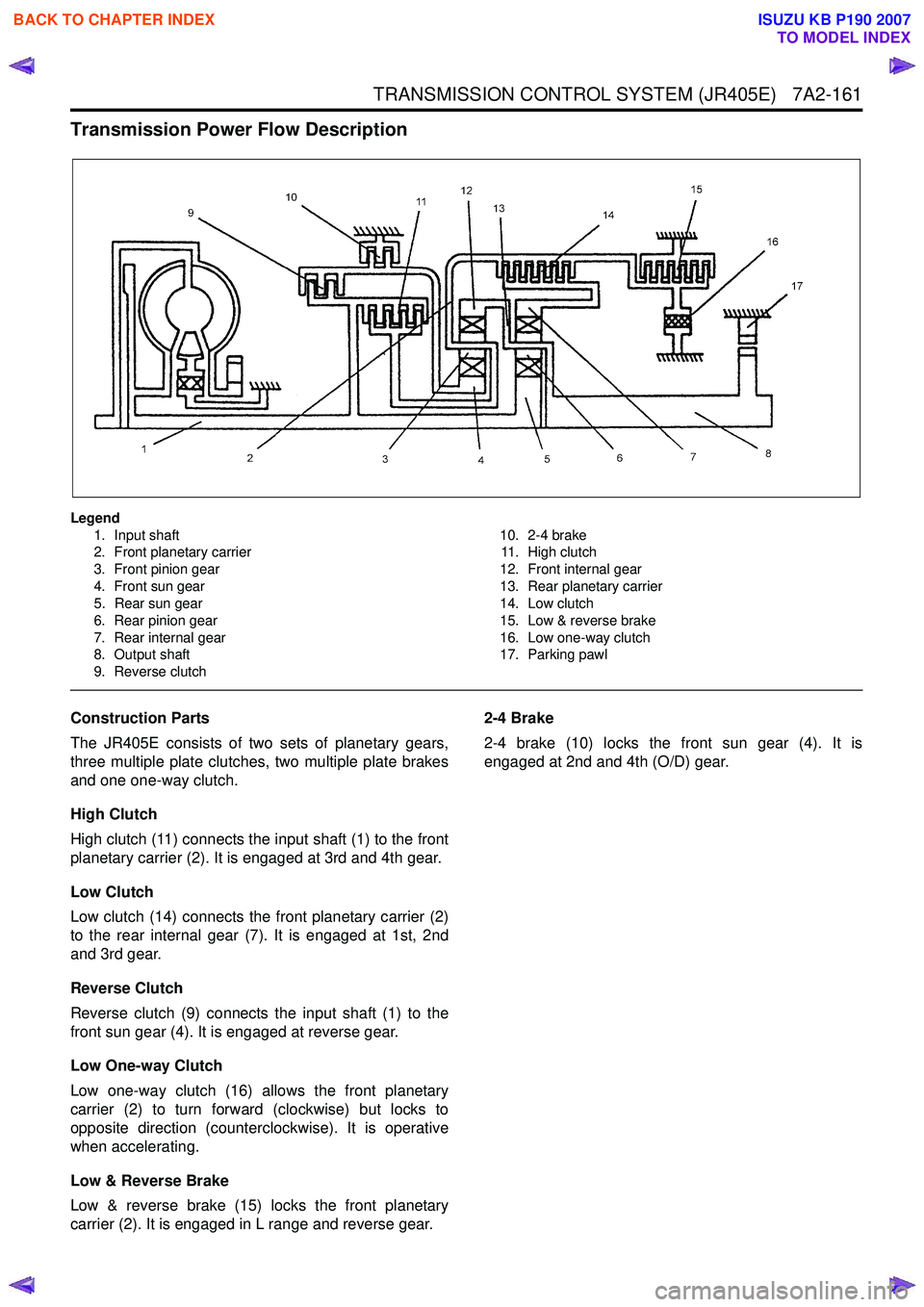
Transmission Power Flow Description
Legend1. Input shaft
2. Front planetary carrier
3. Front pinion gear
4. Front sun gear
5. Rear sun gear
6. Rear pinion gear
7. Rear internal gear
8. Output shaft
9. Reverse clutch 10. 2-4 brake
11. High clutch
12. Front internal gear
13. Rear planetary carrier
14. Low clutch
15. Low & reverse brake
16. Low one-way clutch
17. Parking pawl
Construction Parts
The JR405E consists of two sets of planetary gears,
three multiple plate clutches, two multiple plate brakes
and one one-way clutch.
High Clutch
High clutch (11) connects the input shaft (1) to the front
planetary carrier (2). It is engaged at 3rd and 4th gear.
Low Clutch
Low clutch (14) connects the front planetary carrier (2)
to the rear internal gear (7). It is engaged at 1st, 2nd
and 3rd gear.
Reverse Clutch
Reverse clutch (9) connects the input shaft (1) to the
front sun gear (4). It is engaged at reverse gear.
Low One-way Clutch
Low one-way clutch (16) allows the front planetary
carrier (2) to turn forward (clockwise) but locks to
opposite direction (counterclockwise). It is operative
when accelerating.
Low & Reverse Brake
Low & reverse brake (15) locks the front planetary
carrier (2). It is engaged in L range and reverse gear. 2-4 Brake
2-4 brake (10) locks the front sun gear (4). It is
engaged at 2nd and 4th (O/D) gear.
BACK TO CHAPTER INDEX
TO MODEL INDEX
ISUZU KB P190 2007
Page 4809 of 6020
CLUTCH 7C-31
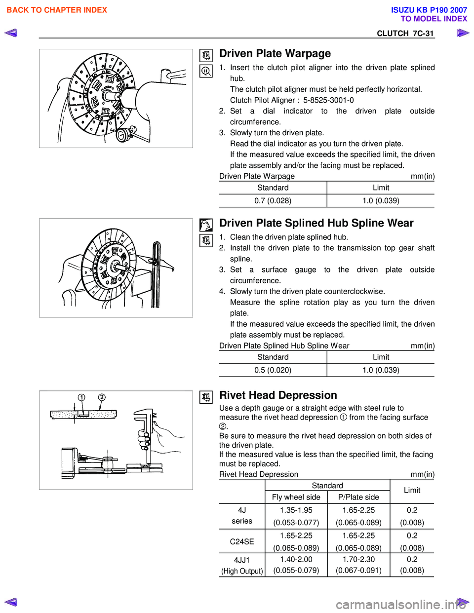
Driven Plate Warpage
1. Insert the clutch pilot aligner into the driven plate splinedhub.
The clutch pilot aligner must be held perfectly horizontal.
Clutch Pilot Aligner : 5-8525-3001-0
2. Set a dial indicator to the driven plate outside circumference.
3. Slowly turn the driven plate.
Read the dial indicator as you turn the driven plate.
If the measured value exceeds the specified limit, the driven plate assembly and/or the facing must be replaced.
Driven Plate W arpage mm(in)
Standard Limit
0.7 (0.028)1.0 (0.039)
Driven Plate Splined Hub Spline Wear
1. Clean the driven plate splined hub.
2. Install the driven plate to the transmission top gear shaft spline.
3. Set a surface gauge to the driven plate outside circumference.
4. Slowly turn the driven plate counterclockwise.
Measure the spline rotation play as you turn the driven plate.
If the measured value exceeds the specified limit, the driven plate assembly must be replaced.
Driven Plate Splined Hub Spline W ear mm(in)
Standard Limit
0.5 (0.020)1.0 (0.039)
Rivet Head Depression
Use a depth gauge or a straight edge with steel rule to
measure the rivet head depression
1 from the facing surface
2.
Be sure to measure the rivet head depression on both sides of
the driven plate.
If the measured value is less than the specified limit, the facing
must be replaced.
Rivet Head Depression mm(in)
Standard
Fly wheel side P/Plate side Limit
4J
series 1.35-1.95
(0.053-0.077) 1.65-2.25
(0.065-0.089) 0.2
(0.008)
C24SE 1.65-2.25
(0.065-0.089) 1.65-2.25
(0.065-0.089) 0.2
(0.008)
4JJ1
(High Output)
1.40-2.00
(0.055-0.079) 1.70-2.30
(0.067-0.091) 0.2
(0.008)
BACK TO CHAPTER INDEX
TO MODEL INDEX
ISUZU KB P190 2007
Page 5596 of 6020
Cruise Control – HFV6 Page 8C–18
Step Action Yes No
24 1 Disconnect the PIM connector B – 97.
2 Using a multimeter set to measure voltage, back probe between the harness connector B – 97 pin 15 and a known ground.
3 With the aid of an assistant, monitor the voltage on the multimeter and press and release the cruise control switch to
SET–COAST button.
• With the switch in the rest position, the multimeter should
display 0 V.
• With the switch pressed, the multimeter should display
battery voltage.
Does the multimeter display as described? Go to Step 30 Check for short to
ground or open
circuit on circuit.
Repair as required (refer to Note 1).
Go to Step 32
25 1 Disconnect the PIM connector B – 97.
2 Using a multimeter set to measure voltage, back probe between the harness connector B – 97 pin 17 and a known ground.
3 W ith the aid of an assistant, monitor the voltage on the multimeter and rotate and release the cruise control switch to
CANCEL position.
• With the switch in the rest position, the multimeter should
display 0 V.
• W ith the switch rotated clockwise, the multimeter should
display battery voltage.
Does the multimeter display as described? Go to Step 30 Check for short to
ground or open
circuit on circuit.
Repair as required (refer to Note 1).
Go to Step 32
26 1 Disconnect the ECM connector C – 56.
2 Using a multimeter set to measure voltage, back probe between the harness connector C – 56 pin 10 and ground.
3 With the aid of an assistant, monitor the voltage on the multimeter and press and release the brake pedal.
• W ith the brake pedal in the rest position, the multimeter
should display 0 V
• W ith the brake pedal pressed, the multimeter should
display battery voltage
Does the multimeter display as described? Go to Step 30 Check for a blown
fuse C-18.
Check for short to
ground or open circuit
Repair as required (refer to Note 1).
Go to Step 32
27 1 Disconnect the ECM connector C – 56.
2 Using a multimeter set to measure voltage, back probe between the harness connector C – 56 pin 46 and ground.
3 With the aid of an assistant, monitor the voltage on the multimeter and press and release the brake pedal.
• W ith the brake pedal in the rest position, the multimeter
should display battery voltage
• W ith the brake pedal pressed, the multimeter should
display 0 V.
Does the multimeter display as described? Go to Step 28 Check for a blown
fuse C-10.
Check for short to ground or open
circuit
Repair as required (refer to Note 1).
Go to Step 32
BACK TO CHAPTER INDEX TO MODEL INDEXISUZU KB P190 2007