Page 1029 of 6020

6D – 28 ENGINE ELECTRICAL
BRUSH AND BRUSH HOLDER
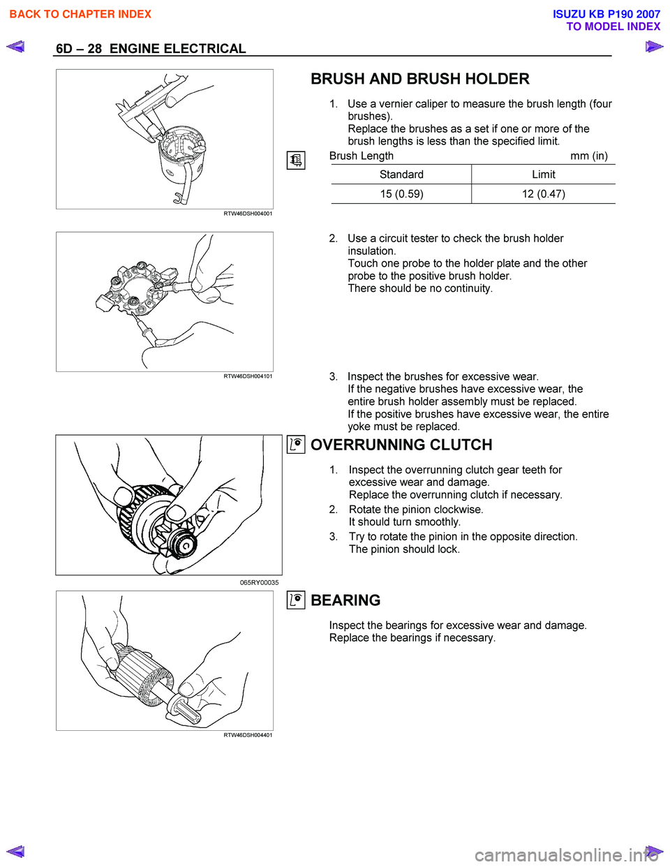
1. Use a vernier caliper to measure the brush length (four
brushes).
Replace the brushes as a set if one or more of the
brush lengths is less than the specified limit.
Brush Length mm (in)
Standard Limit
15 (0.59) 12 (0.47)
RTW46DSH004001
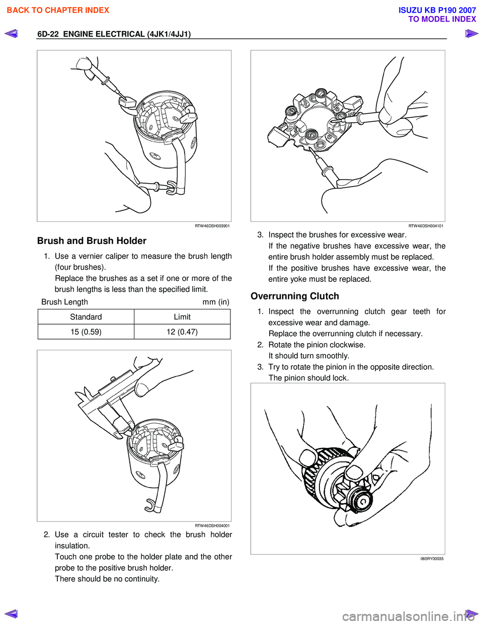
RTW46DSH004101
2. Use a circuit tester to check the brush holder
insulation.
Touch one probe to the holder plate and the other
probe to the positive brush holder.
There should be no continuity.
3. Inspect the brushes for excessive wear. If the negative brushes have excessive wear, the
entire brush holder assembly must be replaced.
If the positive brushes have excessive wear, the entire
yoke must be replaced.
OVERRUNNING CLUTCH
1. Inspect the overrunning clutch gear teeth for excessive wear and damage.
Replace the overrunning clutch if necessary.
2. Rotate the pinion clockwise. It should turn smoothly.
3. Try to rotate the pinion in the opposite direction. The pinion should lock.
065RY00035
RTW46DSH004401
BEARING
Inspect the bearings for excessive wear and damage.
Replace the bearings if necessary.
BACK TO CHAPTER INDEX
TO MODEL INDEX
ISUZU KB P190 2007
Page 1507 of 6020
ENGINE MECHANICAL (4JK1/4JJ1) 6A-147
Reassembly
1. Install the gasket on the element.
2. Install the element.
3. Tighten the element fixing nut using the specified torque.
Tightening torque: 25 N ⋅
⋅⋅
⋅
m (2.5 kg ⋅
⋅⋅
⋅
m / 18 lb ft)
Installation
1. Install the oil filter and cooler.
• Install the O-ring on the oil filter and cooler,
apply grease.
•
Apply the liquid gasket and mount within 5
minutes. Apply liquid gasket (ThreeBond TB-
1207C or equivalent) to the flange surface
groove (cylinder block). Bead diameter must
be between 2 and 3 mm (0.079 and 0.118 in).
Refer to the illustration for the offset position
(no more than 1 mm (0.004 in)).
RTW 56ASH013101
Legend
1. Liquid Gasket
2. O-ring
• Align the oil filter and cooler holes with the
cylinder block studs. Install the oil cooler to the
cylinder clock.
BACK TO CHAPTER INDEX
TO MODEL INDEX
ISUZU KB P190 2007
Page 1610 of 6020

6D-22 ENGINE ELECTRICAL (4JK1/4JJ1)
RTW 46DSH003901
Brush and Brush Holder
1. Use a vernier caliper to measure the brush length
(four brushes).
Replace the brushes as a set if one or more of the brush lengths is less than the specified limit.
Brush Length mm (in)
Standard Limit
15 (0.59) 12 (0.47)
RTW 46DSH004001
2. Use a circuit tester to check the brush holder
insulation.
Touch one probe to the holder plate and the othe
r
probe to the positive brush holder.
There should be no continuity.
RTW 46DSH004101
3. Inspect the brushes for excessive wear.
If the negative brushes have excessive wear, the entire brush holder assembly must be replaced.
If the positive brushes have excessive wear, the entire yoke must be replaced.
Overrunning Clutch
1. Inspect the overrunning clutch gear teeth for
excessive wear and damage.
Replace the overrunning clutch if necessary.
2. Rotate the pinion clockwise.
It should turn smoothly.
3. Try to rotate the pinion in the opposite direction.
The pinion should lock.
065RY00035
BACK TO CHAPTER INDEX
TO MODEL INDEX
ISUZU KB P190 2007
Page 2587 of 6020
Engine Mechanical – V6 Page 6A1–108
Primary Timing Chain Tensioner
Figure 6A1 – 133
1 Inspect the primary timing chain tensioner for worn shoe surface (1), refer to Figure 6A1 – 133.
2 Inspect the tensioner for a locked or binding tensioner shaft (2). Reset the plunger (3) and ensure the tensioner shaft moves freely in and out of the body of the tensioner.
NOTE
To reset the tensioner, use a suitably sized flat
blade screwdriver or Tool No. J 45027 (4) to wind
the plunger in a clockwise direction, into the
tensioner shaft.
3 Replace a damaged tensioner as required.
Left-hand Secondary Timing Chain Guide
1 Inspect the left-hand secondary timing chain guide for the following:
• worn guide surface (1),
• cracked or broken guide surface (2), and
• cracked or damaged guide base (3).
2 Replace a damaged guide as required.
Figure 6A1 – 134
BACK TO CHAPTER INDEX
TO MODEL INDEX
ISUZU KB P190 2007
Page 2589 of 6020

Engine Mechanical – V6 Page 6A1–110
2 Inspect the tensioner for locked or binding tensioner shaft (2). Reset the plunger (3) and ensure the tensioner shaft
moves freely in and out of the body of the tensioner.
NOTE
To reset the tensioner, use a suitably sized flat
blade screwdriver or Tool No. J 45027 (4) to wind
the plunger in a clockwise direction, into the
tensioner shaft.
3 Replace a damaged tensioner as required.
Right-hand Secondary Timing Chain Guide
1 Inspect the right-hand secondary timing chain guide for the following:
• worn guide surface (1),
• cracked or broken guide surface (2), and
• cracked or damaged guide base (3).
2 Replace a damaged guide as required.
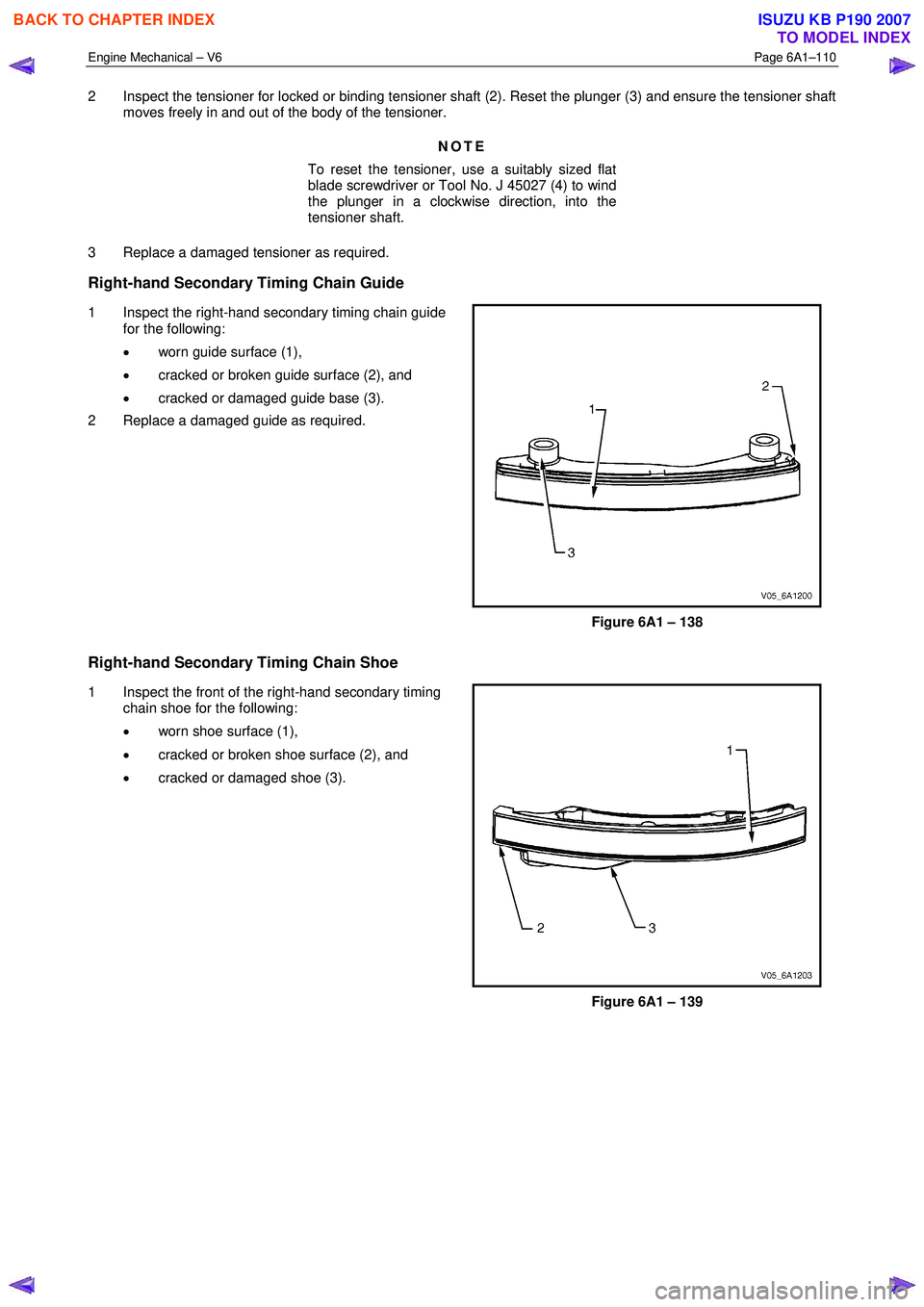
Figure 6A1 – 138
Right-hand Secondary Timing Chain Shoe
1 Inspect the front of the right-hand secondary timing chain shoe for the following:
• worn shoe surface (1),
• cracked or broken shoe surface (2), and
• cracked or damaged shoe (3).
Figure 6A1 – 139
BACK TO CHAPTER INDEX
TO MODEL INDEX
ISUZU KB P190 2007
Page 2590 of 6020
Engine Mechanical – V6 Page 6A1–111
2 Inspect the back of the shoe for a damaged, worn or
missing timing chain tensioner contact pad (1).
Replace a damaged shoe as required.
Figure 6A1 – 140
Right-hand Secondary Timing Chain Tensioner
Figure 6A1 – 141
1 Inspect the right-hand secondary timing chain tensioner for damaged plunger-to-shoe contact surface (1), refer to Figure 6A1 – 141.
NOTE
To reset the tensioner, use a suitably sized flat
blade screwdriver or Tool No. J 45027 (4) to wind
the plunger in a clockwise direction, into the
tensioner shaft.
2 Inspect the tensioner for a locked or binding tensioner shaft (2). Reset the plunger (3) and ensure the tensioner shaft moves freely in and out of the body of the tensioner.
3 Replace a damaged tensioner as required.
Reinstall
Left-hand Secondary Timing Chain Components
BACK TO CHAPTER INDEX
TO MODEL INDEX
ISUZU KB P190 2007
Page 2597 of 6020
Engine Mechanical – V6 Page 6A1–118
21 Install the left-hand secondary timing chain shoe
bolt (1) and tighten to the correct torque specification.
NOTE
Ensure secondary timing chain shoe is clear of
the left-hand secondary timing chain tensioner
mounting pad, before tightening the attaching
bolt.
Secondary timing chain shoe attaching
bolt torque specification ..........................20.0 – 26.0 Nm
Figure 6A1 – 158
22 Ensure the left-hand secondary timing chain tensioner is selected and orientated correctly.
Figure 6A1 – 159
23 Reset the left-hand secondary timing chain tensioner.
NOTE
To reset the tensioner, use a suitably sized flat
blade screwdriver (1) or Tool No. J 45027 (4) to
wind the plunger in a clockwise direction, into
the tensioner shaft (2).
Figure 6A1 – 160
BACK TO CHAPTER INDEX
TO MODEL INDEX
ISUZU KB P190 2007
Page 2604 of 6020
Engine Mechanical – V6 Page 6A1–125
13 Install the primary timing chain upper guide (1).
14 Install the primary timing chain upper guide bolts (2) and tighten to the correct torque specification.
Primary timing chain upper guide
attaching bolt torque specification ...........20.0 – 26.0 Nm
Figure 6A1 – 179
15 Ensure that the primary timing chain tensioner is being installed.
Figure 6A1 – 180
16 Reset the primary timing chain tensioner.
NOTE
To reset the tensioner, use a suitably sized flat
blade screwdriver (1) or Tool No. J 45027 (4) to
wind the plunger in a clockwise direction, into
the tensioner shaft (2).
Figure 6A1 – 181
BACK TO CHAPTER INDEX
TO MODEL INDEX
ISUZU KB P190 2007