2007 ISUZU KB P190 oil temperature
[x] Cancel search: oil temperaturePage 1373 of 6020
ENGINE MECHANICAL (4JK1/4JJ1) 6A-13
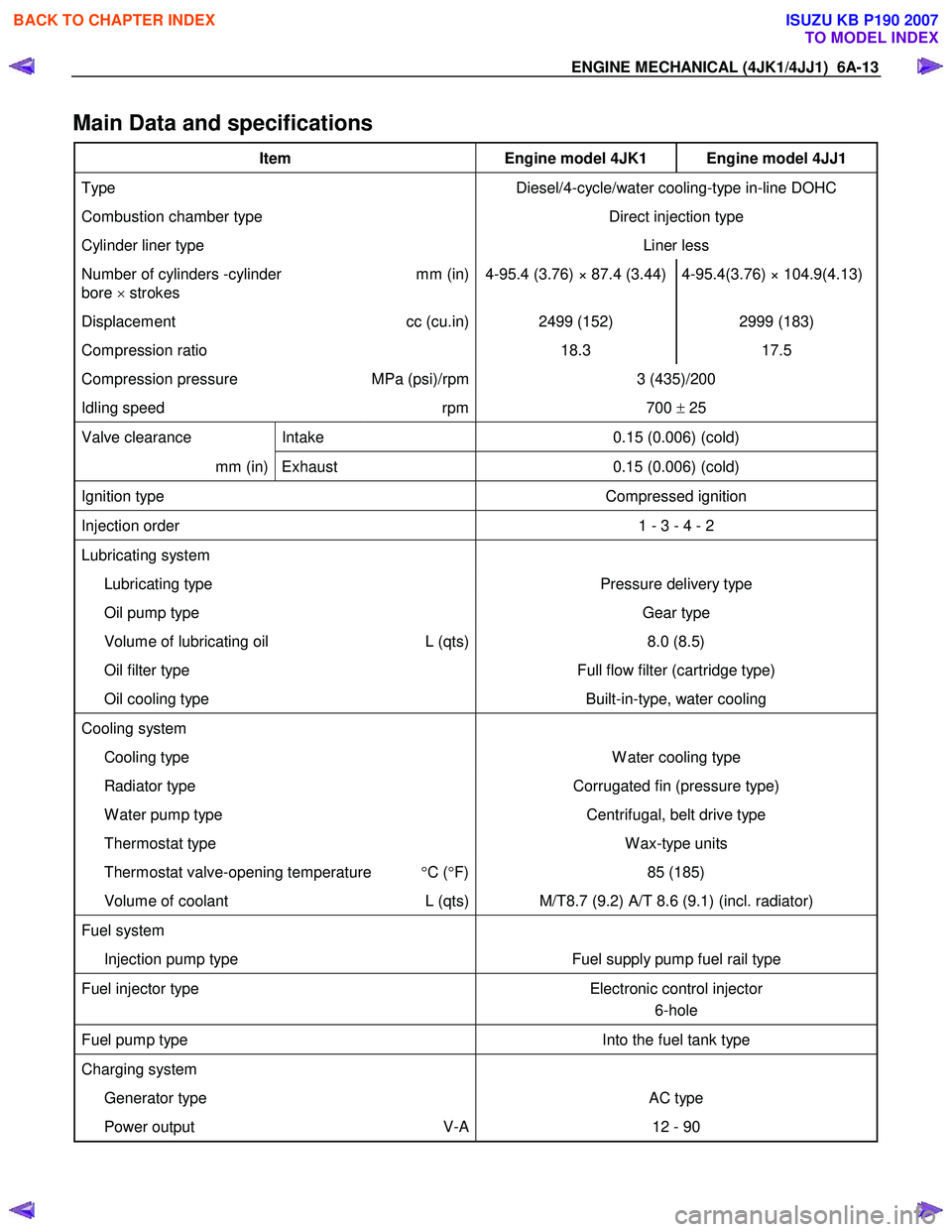
Main Data and specifications
Item Engine model 4JK1 Engine model 4JJ1
Type Diesel/4-cycle/water cooling-type in-line DOHC
Combustion chamber type Direct injection type
Cylinder liner type Liner less
Number of cylinders -cylinder
bore × strokes mm (in) 4-95.4 (3.76) × 87.4 (3.44) 4-95.4(3.76) × 104.9(4.13)
Displacement
cc (cu.in) 2499 (152) 2999 (183)
Compression ratio 18.3 17.5
Compression pressure MPa (psi)/rpm 3 (435)/200
Idling speed rpm 700 ± 25
Valve clearance Intake 0.15 (0.006) (cold)
mm (in) Exhaust 0.15 (0.006) (cold)
Ignition type Compressed ignition
Injection order 1 - 3 - 4 - 2
Lubricating system
Lubricating type Pressure delivery type
Oil pump type Gear type
Volume of lubricating oil L (qts) 8.0 (8.5)
Oil filter type Full flow filter (cartridge type)
Oil cooling type Built-in-type, water cooling
Cooling system
Cooling type W ater cooling type
Radiator type Corrugated fin (pressure type)
W ater pump type Centrifugal, belt drive type
Thermostat type W ax-type units
Thermostat valve-opening temperature °C ( °F) 85 (185)
Volume of coolant L (qts) M/T8.7 (9.2) A/T 8.6 (9.1) (incl. radiator)
Fuel system
Injection pump type Fuel supply pump fuel rail type
Fuel injector type Electronic control injector
6-hole
Fuel pump type Into the fuel tank type
Charging system
Generator type AC type
Power output V-A 12 - 90
BACK TO CHAPTER INDEX
TO MODEL INDEX
ISUZU KB P190 2007
Page 1457 of 6020
ENGINE MECHANICAL (4JK1/4JJ1) 6A-97
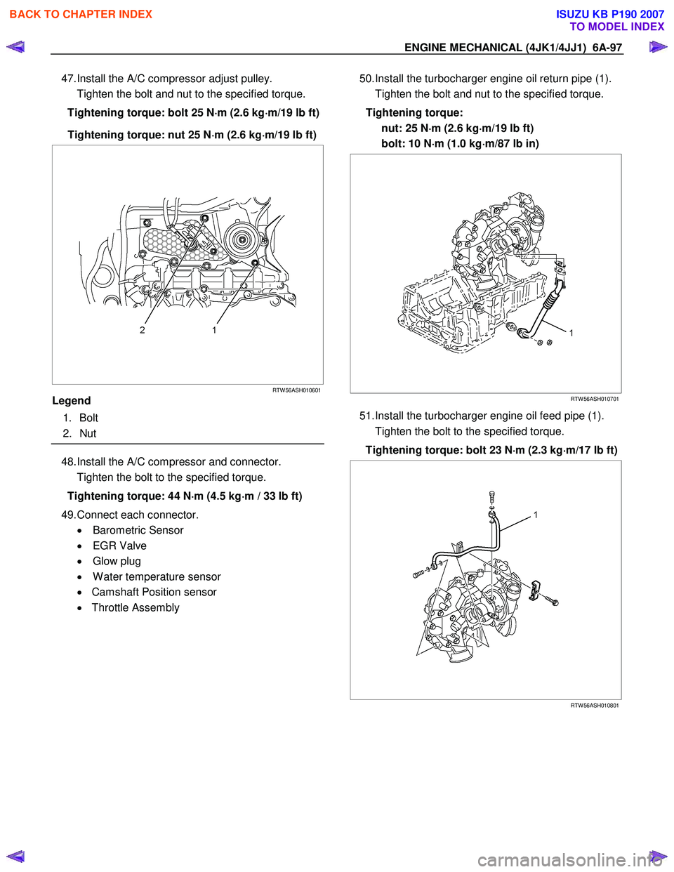
47. Install the A/C compressor adjust pulley.
Tighten the bolt and nut to the specified torque.
Tightening torque: bolt 25 N ⋅
⋅⋅
⋅
m (2.6 kg ⋅
⋅⋅
⋅
m/19 lb ft)
Tightening torque: nut 25 N ⋅
⋅⋅
⋅
m (2.6 kg ⋅
⋅⋅
⋅
m/19 lb ft)
RTW 56ASH010601
Legend
1. Bolt
2. Nut
48. Install the A/C compressor and connector.
Tighten the bolt to the specified torque.
Tightening torque: 44 N ⋅
⋅⋅
⋅
m (4.5 kg ⋅
⋅⋅
⋅
m / 33 lb ft)
49. Connect each connector. • Barometric Sensor
• EGR Valve
• Glow plug
• W ater temperature sensor
• Camshaft Position sensor
• Throttle Assembly
50. Install the turbocharger engine oil return pipe (1).
Tighten the bolt and nut to the specified torque.
Tightening torque: nut: 25 N ⋅
⋅⋅
⋅
m (2.6 kg ⋅
⋅⋅
⋅
m/19 lb ft)
bolt: 10 N ⋅
⋅⋅
⋅
m (1.0 kg ⋅
⋅⋅
⋅
m/87 lb in)
RTW 56ASH010701
51. Install the turbocharger engine oil feed pipe (1).
Tighten the bolt to the specified torque.
Tightening torque: bolt 23 N ⋅
⋅⋅
⋅
m (2.3 kg ⋅
⋅⋅
⋅
m/17 lb ft)
RTW 56ASH010801
BACK TO CHAPTER INDEX
TO MODEL INDEX
ISUZU KB P190 2007
Page 1466 of 6020
6A-106 ENGINE MECHANICAL (4JK1/4JJ1)
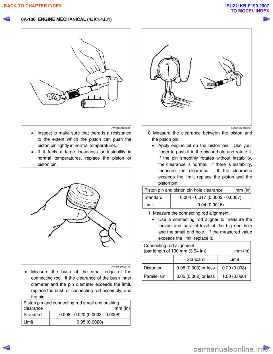
LNW 21BSH009601
• Inspect to make sure that there is a resistance
to the extent which the piston can push the
piston pin lightly in normal temperatures.
• If it feels a large looseness or instability in
normal temperatures, replace the piston o
r
piston pin.
LNW 21BSH009701
• Measure the bush of the small edge of the
connecting rod. If the clearance of the bush inne
r
diameter and the pin diameter exceeds the limit,
replace the bush or connecting rod assembly, and
the pin.
Piston pin and connecting rod small end bushing
clearance mm (in)
Standard 0.008 - 0.020 (0.0003 - 0.0008)
Limit 0.05 (0.0020)
LNW 21BSH009801
10. Measure the clearance between the piston and
the piston pin.
•
Apply engine oil on the piston pin. Use your
finger to push it in the piston hole and rotate it.
If the pin smoothly rotates without instability,
the clearance is normal. If there is instability,
measure the clearance. If the clearance
exceeds the limit, replace the piston and the
piston pin.
Piston pin and piston pin hole clearance mm (in)
Standard 0.004 - 0.017 (0.0002 - 0.0007)
Limit 0.04 (0.0016)
11. Measure the connecting rod alignment.
• Use a connecting rod aligner to measure the
torsion and parallel level of the big end hole
and the small end hole. If the measured value
exceeds the limit, replace it.
Connecting rod alignment
(par length of 100 mm (3.94 in)) mm (in)
Standard Limit
Distortion 0.08 (0.003) or less 0.20 (0.008)
Parallelism 0.05 (0.002) or less 1.50 (0.060)
BACK TO CHAPTER INDEX
TO MODEL INDEX
ISUZU KB P190 2007
Page 1529 of 6020
6B-6 ENGINE COOLING (4JK1/4JJ1)
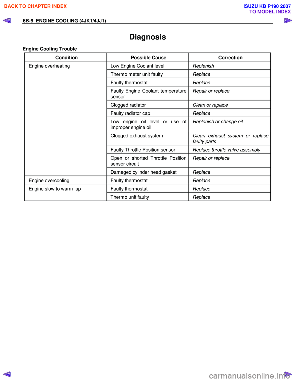
Diagnosis
Engine Cooling Trouble
Condition Possible Cause Correction
Low Engine Coolant level Replenish
Thermo meter unit faulty Replace
Faulty thermostat Replace
Faulty Engine Coolant temperature
sensor Repair or replace
Clogged radiator
Clean or replace
Faulty radiator cap Replace
Low engine oil level or use of
improper engine oil Replenish or change oil
Clogged exhaust system
Clean exhaust system or replace
faulty parts
Faulty Throttle Position sensor Replace throttle valve assembly
Open or shorted Throttle Position
sensor circuit Repair or replace
Engine overheating
Damaged cylinder head gasket Replace
Engine overcooling Faulty thermostat Replace
Faulty thermostat Replace Engine slow to warm–up
Thermo unit faulty Replace
BACK TO CHAPTER INDEX
TO MODEL INDEX
ISUZU KB P190 2007
Page 1530 of 6020
ENGINE COOLING (4JK1/4JJ1) 6B-7
Draining and Refilling Cooling System
Before draining the cooling system, inspect the system
and perform any necessary service to ensure that it is
clean, does not leak and is in proper working order.
The engine coolant (EC) level should be between the
“MIN" and “MAX" lines of the reserve tank when the
engine is cold. If low, check for leakage and add EC up
to the “MAX" line.
There should not be any excessive deposit of rust o
r
scales around the radiator cap or radiator filler hole, and
the EC should also be free from oil.
Replace the EC if excessively dirty.
1. Remove the radiator skid plate.
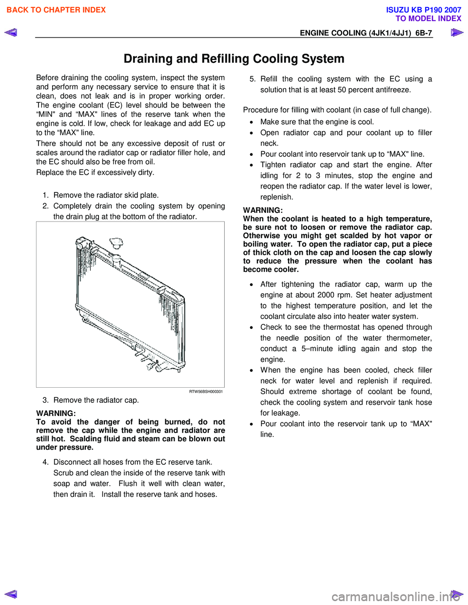
2. Completely drain the cooling system by opening the drain plug at the bottom of the radiator.
RTW 56BSH000301
3. Remove the radiator cap.
WARNING:
To avoid the danger of being burned, do not
remove the cap while the engine and radiator are
still hot. Scalding fluid and steam can be blown out
under pressure.
4. Disconnect all hoses from the EC reserve tank.
Scrub and clean the inside of the reserve tank with soap and water. Flush it well with clean water,
then drain it. Install the reserve tank and hoses.
5. Refill the cooling system with the EC using a
solution that is at least 50 percent antifreeze.
Procedure for filling with coolant (in case of full change).
• Make sure that the engine is cool.
• Open radiator cap and pour coolant up to fille
r
neck.
• Pour coolant into reservoir tank up to “MAX" line.
• Tighten radiator cap and start the engine. Afte
r
idling for 2 to 3 minutes, stop the engine and
reopen the radiator cap. If the water level is lower,
replenish.
WARNING:
When the coolant is heated to a high temperature,
be sure not to loosen or remove the radiator cap.
Otherwise you might get scalded by hot vapor o
r
boiling water. To open the radiator cap, put a piece
of thick cloth on the cap and loosen the cap slowly
to reduce the pressure when the coolant has
become cooler.
• After tightening the radiator cap, warm up the
engine at about 2000 rpm. Set heater adjustment
to the highest temperature position, and let the
coolant circulate also into heater water system.
• Check to see the thermostat has opened through
the needle position of the water thermometer,
conduct a 5–minute idling again and stop the
engine.
• W hen the engine has been cooled, check fille
r
neck for water level and replenish if required.
Should extreme shortage of coolant be found,
check the cooling system and reservoir tank hose
for leakage.
• Pour coolant into the reservoir tank up to “MAX"
line.
BACK TO CHAPTER INDEX
TO MODEL INDEX
ISUZU KB P190 2007
Page 1945 of 6020
6E-328 ENGINE CONTROL SYSTEM (4JK1/4JJ1)
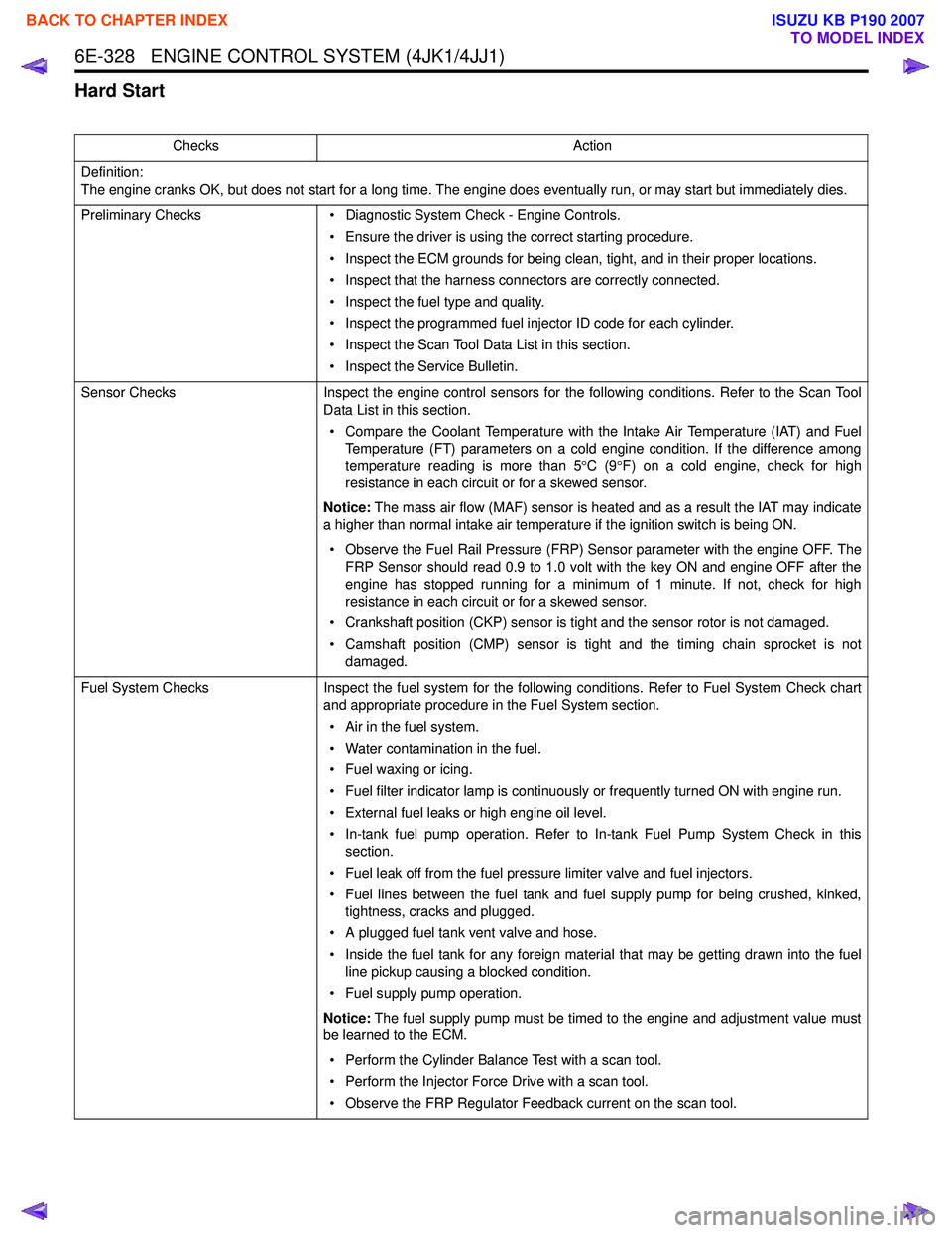
Hard Start
ChecksAction
Definition:
The engine cranks OK, but does not start for a long time. The engine does eventually run, or may start but immediately dies.
Preliminary Checks • Diagnostic System Check - Engine Controls.
• Ensure the driver is using the correct starting procedure.
• Inspect the ECM grounds for being clean, tight, and in their proper locations.
• Inspect that the harness connectors are correctly connected.
• Inspect the fuel type and quality.
• Inspect the programmed fuel injector ID code for each cylinder.
• Inspect the Scan Tool Data List in this section.
• Inspect the Service Bulletin.
Sensor Checks Inspect the engine control sensors for the following conditions. Refer to the Scan Tool
Data List in this section.
• Compare the Coolant Temperature with the Intake Air Temperature (IAT) and Fuel Temperature (FT) parameters on a cold engine condition. If the difference among
temperature reading is more than 5 °C (9 °F) on a cold engine, check for high
resistance in each circuit or for a skewed sensor.
Notice: The mass air flow (MAF) sensor is heated and as a result the IAT may indicate
a higher than normal intake air temperature if the ignition switch is being ON.
• Observe the Fuel Rail Pressure (FRP) Sensor parameter with the engine OFF. The FRP Sensor should read 0.9 to 1.0 volt with the key ON and engine OFF after the
engine has stopped running for a minimum of 1 minute. If not, check for high
resistance in each circuit or for a skewed sensor.
• Crankshaft position (CKP) sensor is tight and the sensor rotor is not damaged.
• Camshaft position (CMP) sensor is tight and the timing chain sprocket is not damaged.
Fuel System Checks Inspect the fuel system for the following conditions. Refer to Fuel System Check chart
and appropriate procedure in the Fuel System section.
• Air in the fuel system.
• Water contamination in the fuel.
• Fuel waxing or icing.
• Fuel filter indicator lamp is continuously or frequently turned ON with engine run.
• External fuel leaks or high engine oil level.
• In-tank fuel pump operation. Refer to In-tank Fuel Pump System Check in this section.
• Fuel leak off from the fuel pressure limiter valve and fuel injectors.
• Fuel lines between the fuel tank and fuel supply pump for being crushed, kinked, tightness, cracks and plugged.
• A plugged fuel tank vent valve and hose.
• Inside the fuel tank for any foreign material that may be getting drawn into the fuel line pickup causing a blocked condition.
• Fuel supply pump operation.
Notice: The fuel supply pump must be timed to the engine and adjustment value must
be learned to the ECM.
• Perform the Cylinder Balance Test with a scan tool.
• Perform the Injector Force Drive with a scan tool.
• Observe the FRP Regulator Feedback current on the scan tool.
BACK TO CHAPTER INDEX
TO MODEL INDEX
ISUZU KB P190 2007
Page 1947 of 6020
6E-330 ENGINE CONTROL SYSTEM (4JK1/4JJ1)
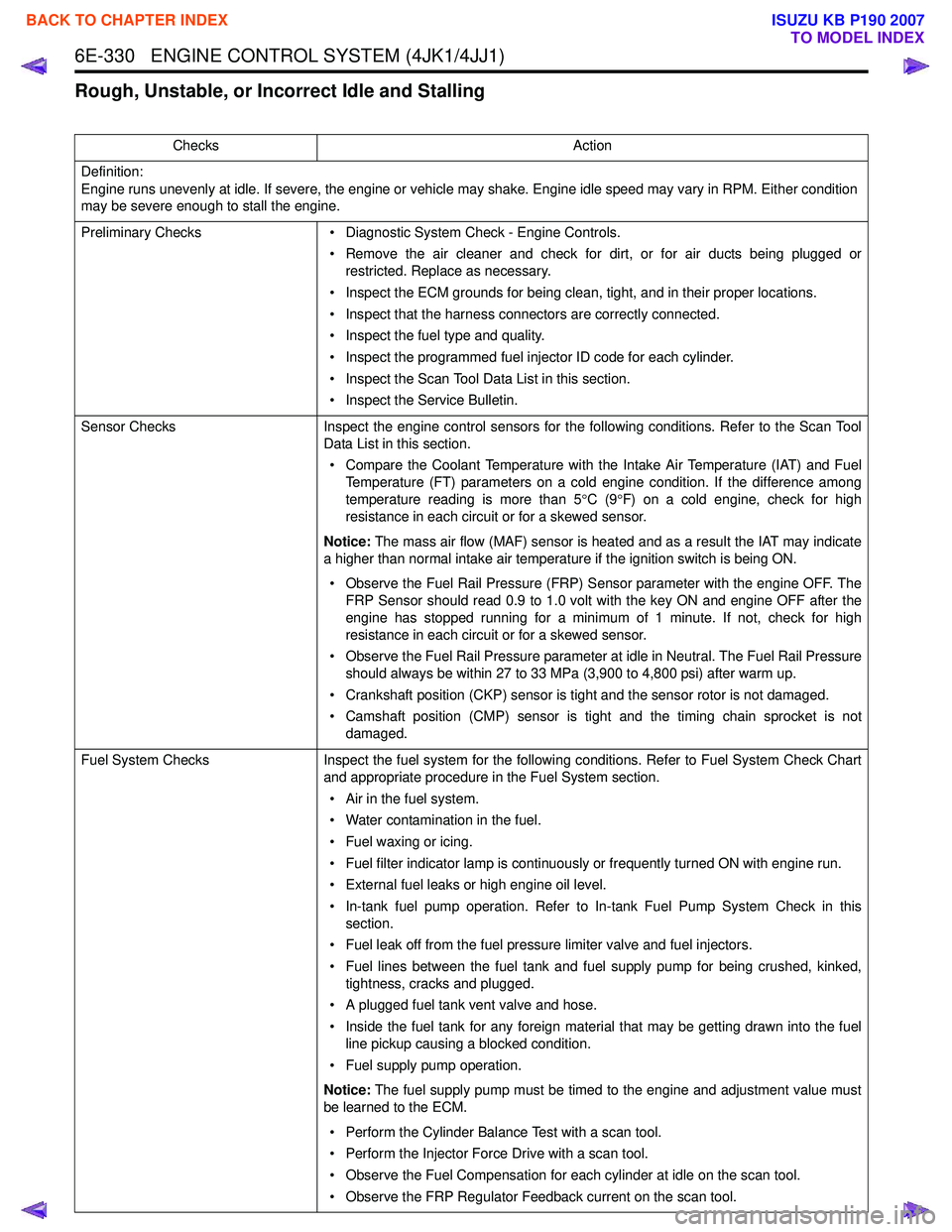
Rough, Unstable, or Incorrect Idle and Stalling
ChecksAction
Definition:
Engine runs unevenly at idle. If severe, the engine or vehicle may shake. Engine idle speed may vary in RPM. Either condition
may be severe enough to stall the engine.
Preliminary Checks • Diagnostic System Check - Engine Controls.
• Remove the air cleaner and check for dirt, or for air ducts being plugged or restricted. Replace as necessary.
• Inspect the ECM grounds for being clean, tight, and in their proper locations.
• Inspect that the harness connectors are correctly connected.
• Inspect the fuel type and quality.
• Inspect the programmed fuel injector ID code for each cylinder.
• Inspect the Scan Tool Data List in this section.
• Inspect the Service Bulletin.
Sensor Checks Inspect the engine control sensors for the following conditions. Refer to the Scan Tool
Data List in this section.
• Compare the Coolant Temperature with the Intake Air Temperature (IAT) and Fuel Temperature (FT) parameters on a cold engine condition. If the difference among
temperature reading is more than 5 °C (9 °F) on a cold engine, check for high
resistance in each circuit or for a skewed sensor.
Notice: The mass air flow (MAF) sensor is heated and as a result the IAT may indicate
a higher than normal intake air temperature if the ignition switch is being ON.
• Observe the Fuel Rail Pressure (FRP) Sensor parameter with the engine OFF. The FRP Sensor should read 0.9 to 1.0 volt with the key ON and engine OFF after the
engine has stopped running for a minimum of 1 minute. If not, check for high
resistance in each circuit or for a skewed sensor.
• Observe the Fuel Rail Pressure parameter at idle in Neutral. The Fuel Rail Pressure should always be within 27 to 33 MPa (3,900 to 4,800 psi) after warm up.
• Crankshaft position (CKP) sensor is tight and the sensor rotor is not damaged.
• Camshaft position (CMP) sensor is tight and the timing chain sprocket is not damaged.
Fuel System Checks Inspect the fuel system for the following conditions. Refer to Fuel System Check Chart
and appropriate procedure in the Fuel System section.
• Air in the fuel system.
• Water contamination in the fuel.
• Fuel waxing or icing.
• Fuel filter indicator lamp is continuously or frequently turned ON with engine run.
• External fuel leaks or high engine oil level.
• In-tank fuel pump operation. Refer to In-tank Fuel Pump System Check in this section.
• Fuel leak off from the fuel pressure limiter valve and fuel injectors.
• Fuel lines between the fuel tank and fuel supply pump for being crushed, kinked, tightness, cracks and plugged.
• A plugged fuel tank vent valve and hose.
• Inside the fuel tank for any foreign material that may be getting drawn into the fuel line pickup causing a blocked condition.
• Fuel supply pump operation.
Notice: The fuel supply pump must be timed to the engine and adjustment value must
be learned to the ECM.
• Perform the Cylinder Balance Test with a scan tool.
• Perform the Injector Force Drive with a scan tool.
• Observe the Fuel Compensation for each cylinder at idle on the scan tool.
• Observe the FRP Regulator Feedback current on the scan tool.
BACK TO CHAPTER INDEX
TO MODEL INDEX
ISUZU KB P190 2007
Page 1949 of 6020
6E-332 ENGINE CONTROL SYSTEM (4JK1/4JJ1)
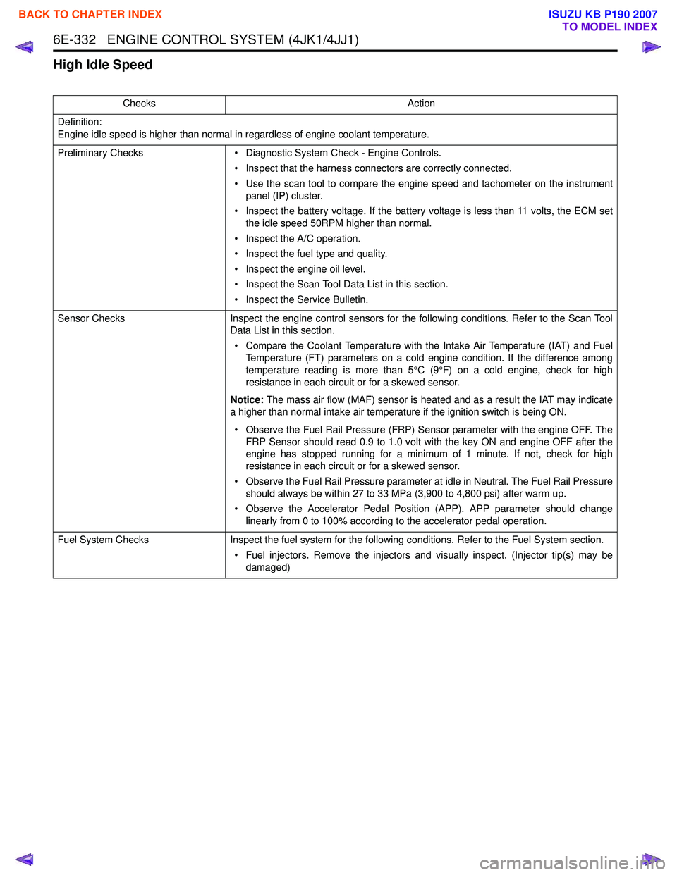
High Idle Speed
ChecksAction
Definition:
Engine idle speed is higher than normal in regardless of engine coolant temperature.
Preliminary Checks • Diagnostic System Check - Engine Controls.
• Inspect that the harness connectors are correctly connected.
• Use the scan tool to compare the engine speed and tachometer on the instrument panel (IP) cluster.
• Inspect the battery voltage. If the battery voltage is less than 11 volts, the ECM set the idle speed 50RPM higher than normal.
• Inspect the A/C operation.
• Inspect the fuel type and quality.
• Inspect the engine oil level.
• Inspect the Scan Tool Data List in this section.
• Inspect the Service Bulletin.
Sensor Checks Inspect the engine control sensors for the following conditions. Refer to the Scan Tool
Data List in this section.
• Compare the Coolant Temperature with the Intake Air Temperature (IAT) and Fuel Temperature (FT) parameters on a cold engine condition. If the difference among
temperature reading is more than 5 °C (9 °F) on a cold engine, check for high
resistance in each circuit or for a skewed sensor.
Notice: The mass air flow (MAF) sensor is heated and as a result the IAT may indicate
a higher than normal intake air temperature if the ignition switch is being ON.
• Observe the Fuel Rail Pressure (FRP) Sensor parameter with the engine OFF. The FRP Sensor should read 0.9 to 1.0 volt with the key ON and engine OFF after the
engine has stopped running for a minimum of 1 minute. If not, check for high
resistance in each circuit or for a skewed sensor.
• Observe the Fuel Rail Pressure parameter at idle in Neutral. The Fuel Rail Pressure should always be within 27 to 33 MPa (3,900 to 4,800 psi) after warm up.
• Observe the Accelerator Pedal Position (APP). APP parameter should change linearly from 0 to 100% according to the accelerator pedal operation.
Fuel System Checks Inspect the fuel system for the following conditions. Refer to the Fuel System section.
• Fuel injectors. Remove the injectors and visually inspect. (Injector tip(s) may be damaged)
BACK TO CHAPTER INDEX
TO MODEL INDEX
ISUZU KB P190 2007