2007 ISUZU KB P190 oil temperature
[x] Cancel search: oil temperaturePage 846 of 6020

ENGINE MECHANICAL 6A – 41
Coolant Replenishment
Warning:
When the coolant is heated to a high temperature, be
sure not to loosen or remove the rediator cap.
Otherwise you might get scalded by hot vapor or
boiling water.
To open the radiator cap, put a piece of thick cloth on
the cap and loosen the cap slowly to reduce the
pressure when the coolant has become cooler.
1. Open rediator cap pour coolant up to filler neck
2. Pour coolant into reservoir tank up to "MAX" line
3. Tighten radiator cap and start the engine. After idling for 2 to 3 minutes, stop the engine and reopen radiator
cap. If the water level is lower, replenish.
4. After replenish the coolant tighten radiator cap, warm up the engine at about 2000 rpm. Set heater
adjustment to the highest temperature position, and let
the coolant circulate also into heater water system.
5. Check to see the thermometer, continuously idling 5 minutes and stop the engine.
6. W hen the engine has been cooled, check filler neck for water level and replenish if required. Should extreme
shortage of coolant is found, check the coolant system
and reservoir tank hose for leakage.
7. Pour coolant into the reservoir tank up to "MAX" line.
Coolant Capacity lit (US/UK gal)
4JA1 / TC 9.4 (2.5 / 2.1)
4JH1TC M/T: 10.1 (2.7 / 2.2)
A/T: 10.0 (2.6 / 2.2)
Engine Warm-Up
After completing the required maintenance procedures,
start the engine and allow it to idle until it is warm.
Check the following:
1. Engine idling speed.
2. Engine noise level.
3. Engine lubricating system and cooling system. Carefully check for oil and coolant leakage.
4. Clutch engagement.
5. Transmission operation.
6. Indicator warning light operation.
BACK TO CHAPTER INDEX
TO MODEL INDEX
ISUZU KB P190 2007
Page 947 of 6020

ENGINE COOLING 6B – 3
MAIN DATA AND SPECIFICATIONS
Description Item M/T A/T
Cooling system
W ater pump type
Pump to crankshaft speed ratio (To 1)
Delivery volume lit (US/UK gal)/min
Pump speed at 3000 rpm
W ater temperature at 30 °C (86 °F)
Pump bearing type
Thermostat type
Valve initial opening temperature °C ( °F)
(Oil cooler thermo valve)
(EGR cooler thermo valve)
Valve full opening temperature °C ( °F)
(Oil cooler thermo valve)
(EGR cooler thermo valve)
Valve lift at fully open position mm (in)
(Oil cooler thermo valve)
(EGR cooler thermo valve) Engine coolant forced circulation
Centrifugal impeller type 1.2
100 (26.3/22.2)
Double row shaft
W ax pellet with jiggle valve 82 (180)
76.5 (170) 40 (104)
95 (203)
90 (194)
55 (131)
9.5 (0.37)
4.5 (0.18)
3.5 (0.14)
Radiator Tube type corrugated
Heat radiation capacity 93.0 kW (79,980 kcal/h)
Heat radiation area 11.63 m2 (1.081ft2)
Radiator front area 0.28m2 (0.026 ft2)
Radiator dry weight 52 N (5.3 kg/11.7 lb) 53 N (5.4 kg/11.9 lb)
Radiator cap valve opening pressure 93.3 ~ 122.7 kPa (13.5 ~ 17.8 psi)
Engine coolant capacity 2.4 lit (5.1 U.S pint) 2.3 lit (4.9 U.S pint)
Engine coolant total capacity 10.1 lit (21.3 U.S pint) 10.0 lit (21.1 U.S pint)
BACK TO CHAPTER INDEX
TO MODEL INDEX
ISUZU KB P190 2007
Page 951 of 6020

ENGINE COOLING 6B – 7
DIAGNOSIS
Engine Cooling Trouble
Symptom Possible Cause Action
Low Engine Coolant level Replenish
Thermo meter unit faulty Replace
Faulty thermostat Replace
Faulty Engine Coolant temperature
sensor Repair or replace
Clogged radiator
Clean or replace
Faulty radiator cap Replace
Low engine oil level or use of
improper engine oil Replenish or change oil
Clogged exhaust system
Clean exhaust system or replace
faulty parts
Faulty Throttle Position sensor Replace throttle valve assembly
Open or shorted Throttle Position
sensor circuit Repair or replace
Engine overheating
Damaged cylinder head gasket Replace
Engine overcooling Faulty thermostat Replace
Faulty thermostat Replace Engine slow to warm–up
Thermo unit faulty Replace
BACK TO CHAPTER INDEX
TO MODEL INDEX
ISUZU KB P190 2007
Page 952 of 6020

6B – 8 ENGINE COOLING
Draining and Refilling Cooling System
Before draining the cooling system, inspect the system and
perform any necessary service to ensure that it is clean, does
not leak and is in proper working order. The engine coolant
(EC) level should be between the “MIN" and “MAX" lines o
f
reserve tank when the engine is cold. If low, check for leakage
and add EC up to the “MAX" line.
There should not be any excessive deposit of rust or scales
around the radiator cap or radiator filler hole, and the EC
should also be free from oil.
Replace the EC if excessively dirty.
P1010064
1. Completely drain the cooling system by opening the drain
plug at the bottom of the radiator.
2. Remove the radiator cap.
WARNING: To avoid the danger of being burned, do not
remove the cap while the engine and radiator are still hot.
Scalding fluid and steam can be blown out unde
r
pressure.
3. Disconnect all hoses from the EC reserve tank.
Scrub and clean the inside of the reserve tank with soap and water. Flush it well with clean water, then drain it.
Install the reserve tank and hoses.
4. Refill the cooling system with the EC using a solution that is at least 50 percent antifreeze.
Procedure for filling with coolant (in case of full change)
• Make sure that the engine is cool.
• Open radiator cap pour coolant up to filler neck.
• Pour coolant into reservoir tank up to “MAX" line.
• Tighten radiator cap and start the engine. After idling for 2
to 3 minutes, stop the engine and reopen radiator cap. If the
water level is lower, replenish.
WARNING: When the coolant is heated to a high
temperature, be sure not to loosen or remove the radiato
r
cap. Otherwise you might get scalded by not vapor or
boiling water. To open the radiator cap, put a piece of
thick cloth on the cap and loosen the cap slowly to reduce
the pressure when the coolant has become cooler.
BACK TO CHAPTER INDEX
TO MODEL INDEX
ISUZU KB P190 2007
Page 1153 of 6020

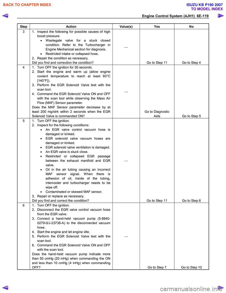
Engine Control System (4JH1) 6E-119
Step Action Value(s) Yes No
3 1. Inspect the following for possible causes of high
boost pressure. • W astegate valve for a stuck closed
condition. Refer to the Turbocharger in
Engine Mechanical section for diagnosis.
• Restricted intake or collapsed hose.
2. Repair the condition as necessary.
Did you find and correction the condition?
Go to Step 11 Go to Step 4
4 1. Turn OFF the ignition for 30 seconds. 2. Start the engine and warm up (allow engine coolant temperature to reach at least 60°C
[140°F]).
3. Perform the EGR Solenoid Valve test with the scan tool.
4. Command the EGR Solenoid Valve ON and OFF with the scan tool while observing the Mass Air
Flow (MAF) Sensor parameter.
Does the MAF Sensor parameter decrease by at
least 200 mg/strk within 2 seconds when the EGR
Solenoid Valve is commanded ON?
Go to Diagnostic Aids Go to Step 5
5 1. Turn OFF the ignition. 2. Inspect for the following conditions: • An EGR valve control vacuum hose is
damaged or kinked.
• EGR solenoid valve vacuum hoses are
damaged or kinked.
• EGR solenoid valve ventilation is damaged.
• An EGR valve is stuck close.
• Restricted or collapsed EGR passage
between the exhaust manifold and EGR
valve.
• Oil in the air tubing causing an incorrect
MAF sensor signal. W hen there is
adhesion of oil, inside of the tubing,
intercooler and turbocharger needs to be
wipe off.
• Contaminated or skewed MAF sensor.
3. Repair or replace as necessary.
Did you find and correct the condition?
Go to Step 11 Go to Step 6
6 1. Turn OFF the ignition. 2. Disconnect the EGR valve control vacuum hose from the EGR valve.
3. Connect a hand-held vacuum pump (5-8840- 0279-0/J-23738-A) to the disconnected vacuum
hose.
4. Start the engine and let engine idle.
5. Perform the EGR Solenoid Valve test with the scan tool.
6. Command the EGR Solenoid Valve ON and OFF with the scan tool.
Does the hand-held vacuum pump indicate more
than 50 cmHg (20 inHg) when commanding the ON
and less than 10 cmHg (4 inHg) when commanding
OFF?
Go to Step 7 Go to Step 10
BACK TO CHAPTER INDEX
TO MODEL INDEX
ISUZU KB P190 2007
Page 1170 of 6020

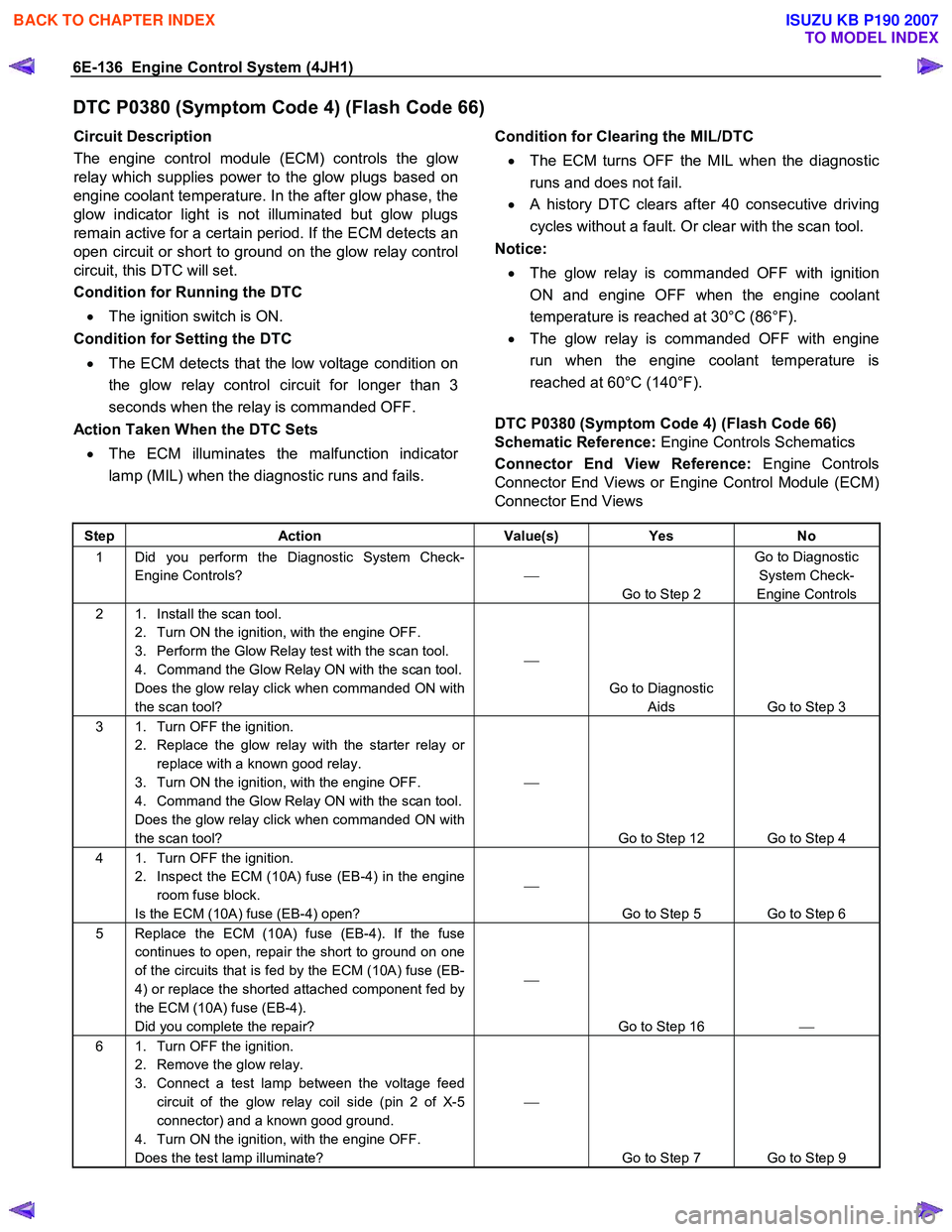
6E-136 Engine Control System (4JH1)
DTC P0380 (Symptom Code 4) (Flash Code 66)
Circuit Description
The engine control module (ECM) controls the glo
w
relay which supplies power to the glow plugs based on
engine coolant temperature. In the after glow phase, the
glow indicator light is not illuminated but glow plugs
remain active for a certain period. If the ECM detects an
open circuit or short to ground on the glow relay control
circuit, this DTC will set.
Condition for Running the DTC
• The ignition switch is ON.
Condition for Setting the DTC
• The ECM detects that the low voltage condition on
the glow relay control circuit for longer than 3
seconds when the relay is commanded OFF.
Action Taken When the DTC Sets
• The ECM illuminates the malfunction indicato
r
lamp (MIL) when the diagnostic runs and fails.
Condition for Clearing the MIL/DTC
• The ECM turns OFF the MIL when the diagnostic
runs and does not fail.
• A history DTC clears after 40 consecutive driving
cycles without a fault. Or clear with the scan tool.
Notice:
• The glow relay is commanded OFF with ignition
ON and engine OFF when the engine coolant
temperature is reached at 30°C (86°F).
• The glow relay is commanded OFF with engine
run when the engine coolant temperature is
reached at 60°C (140°F).
DTC P0380 (Symptom Code 4) (Flash Code 66)
Schematic Reference: Engine Controls Schematics
Connector End View Reference: Engine Controls
Connector End Views or Engine Control Module (ECM)
Connector End Views
Step Action Value(s) Yes No
1 Did you perform the Diagnostic System Check-
Engine Controls?
Go to Step 2 Go to Diagnostic
System Check-
Engine Controls
2 1. Install the scan tool. 2. Turn ON the ignition, with the engine OFF.
3. Perform the Glow Relay test with the scan tool.
4. Command the Glow Relay ON with the scan tool.
Does the glow relay click when commanded ON with
the scan tool?
Go to Diagnostic Aids Go to Step 3
3 1. Turn OFF the ignition. 2. Replace the glow relay with the starter relay or replace with a known good relay.
3. Turn ON the ignition, with the engine OFF.
4. Command the Glow Relay ON with the scan tool.
Does the glow relay click when commanded ON with
the scan tool?
Go to Step 12 Go to Step 4
4 1. Turn OFF the ignition. 2. Inspect the ECM (10A) fuse (EB-4) in the engine room fuse block.
Is the ECM (10A) fuse (EB-4) open?
Go to Step 5 Go to Step 6
5 Replace the ECM (10A) fuse (EB-4). If the fuse continues to open, repair the short to ground on one
of the circuits that is fed by the ECM (10A) fuse (EB-
4) or replace the shorted attached component fed by
the ECM (10A) fuse (EB-4).
Did you complete the repair?
Go to Step 16
6 1. Turn OFF the ignition.
2. Remove the glow relay.
3. Connect a test lamp between the voltage feed circuit of the glow relay coil side (pin 2 of X-5
connector) and a known good ground.
4. Turn ON the ignition, with the engine OFF.
Does the test lamp illuminate?
Go to Step 7 Go to Step 9
BACK TO CHAPTER INDEX
TO MODEL INDEX
ISUZU KB P190 2007
Page 1276 of 6020

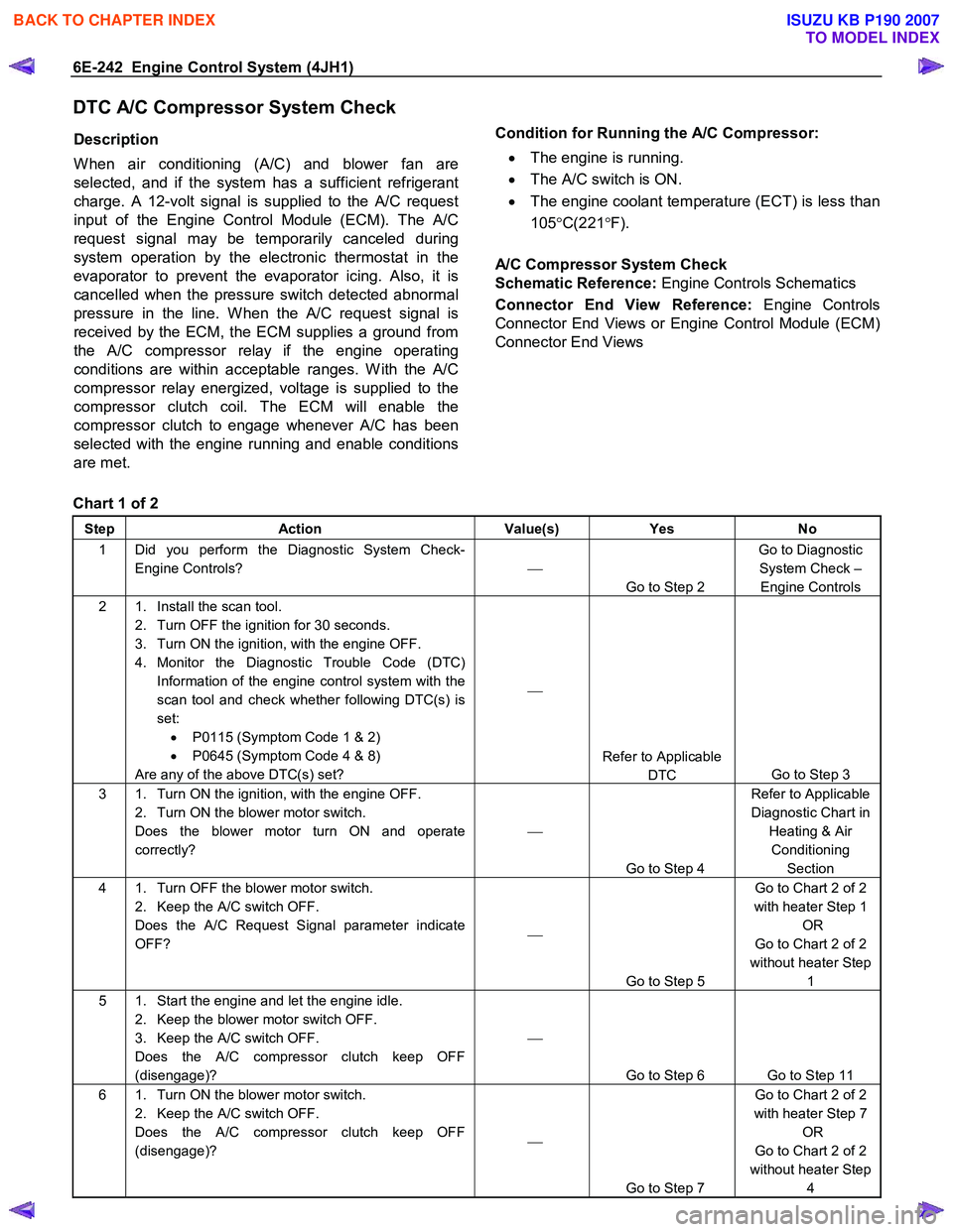
6E-242 Engine Control System (4JH1)
DTC A/C Compressor System Check
Description
W hen air conditioning (A/C) and blower fan are
selected, and if the system has a sufficient refrigerant
charge. A 12-volt signal is supplied to the A/C request
input of the Engine Control Module (ECM). The A/C
request signal may be temporarily canceled during
system operation by the electronic thermostat in the
evaporator to prevent the evaporator icing. Also, it is
cancelled when the pressure switch detected abnormal
pressure in the line. W hen the A/C request signal is
received by the ECM, the ECM supplies a ground from
the A/C compressor relay if the engine operating
conditions are within acceptable ranges. W ith the A/C
compressor relay energized, voltage is supplied to the
compressor clutch coil. The ECM will enable the
compressor clutch to engage whenever A/C has been
selected with the engine running and enable conditions
are met.
Condition for Running the A/C Compressor:
• The engine is running.
• The A/C switch is ON.
• The engine coolant temperature (ECT) is less than
105 °C(221 °F).
A/C Compressor System Check
Schematic Reference: Engine Controls Schematics
Connector End View Reference: Engine Controls
Connector End Views or Engine Control Module (ECM)
Connector End Views
Chart 1 of 2
Step Action Value(s) Yes No
1 Did you perform the Diagnostic System Check-
Engine Controls?
Go to Step 2 Go to Diagnostic
System Check – Engine Controls
2 1. Install the scan tool. 2. Turn OFF the ignition for 30 seconds.
3. Turn ON the ignition, with the engine OFF.
4. Monitor the Diagnostic Trouble Code (DTC) Information of the engine control system with the
scan tool and check whether following DTC(s) is
set: • P0115 (Symptom Code 1 & 2)
• P0645 (Symptom Code 4 & 8)
Are any of the above DTC(s) set?
Refer to Applicable DTC Go to Step 3
3 1. Turn ON the ignition, with the engine OFF.
2. Turn ON the blower motor switch.
Does the blower motor turn ON and operate
correctly?
Go to Step 4 Refer to Applicable
Diagnostic Chart in Heating & Air Conditioning Section
4 1. Turn OFF the blower motor switch. 2. Keep the A/C switch OFF.
Does the A/C Request Signal parameter indicate
OFF?
Go to Step 5 Go to Chart 2 of 2
with heater Step 1 OR
Go to Chart 2 of 2
without heater Step 1
5 1. Start the engine and let the engine idle. 2. Keep the blower motor switch OFF.
3. Keep the A/C switch OFF.
Does the A/C compressor clutch keep OFF
(disengage)?
Go to Step 6 Go to Step 11
6 1. Turn ON the blower motor switch. 2. Keep the A/C switch OFF.
Does the A/C compressor clutch keep OFF
(disengage)?
Go to Step 7 Go to Chart 2 of 2
with heater Step 7 OR
Go to Chart 2 of 2
without heater Step 4
BACK TO CHAPTER INDEX
TO MODEL INDEX
ISUZU KB P190 2007
Page 1293 of 6020

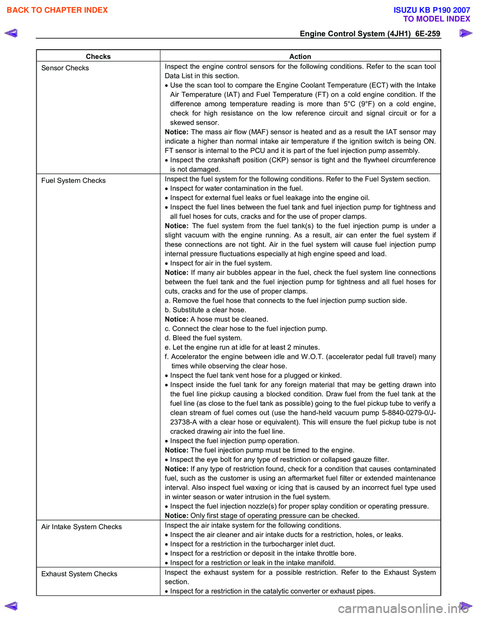
Engine Control System (4JH1) 6E-259
Checks Action
Sensor Checks Inspect the engine control sensors for the following conditions. Refer to the scan tool
Data List in this section.
• Use the scan tool to compare the Engine Coolant Temperature (ECT) with the Intake
Air Temperature (IAT) and Fuel Temperature (FT) on a cold engine condition. If the
difference among temperature reading is more than 5°C (9°F) on a cold engine,
check for high resistance on the low reference circuit and signal circuit or for a
skewed sensor.
Notice: The mass air flow (MAF) sensor is heated and as a result the IAT sensor may
indicate a higher than normal intake air temperature if the ignition switch is being ON.
FT sensor is internal to the PCU and it is part of the fuel injection pump assembly.
• Inspect the crankshaft position (CKP) sensor is tight and the flywheel circumference
is not damaged.
Fuel System Checks Inspect the fuel system for the following conditions. Refer to the Fuel System section.
• Inspect for water contamination in the fuel.
• Inspect for external fuel leaks or fuel leakage into the engine oil.
• Inspect the fuel lines between the fuel tank and fuel injection pump for tightness and
all fuel hoses for cuts, cracks and for the use of proper clamps.
Notice: The fuel system from the fuel tank(s) to the fuel injection pump is under a
slight vacuum with the engine running. As a result, air can enter the fuel system if
these connections are not tight. Air in the fuel system will cause fuel injection pump
internal pressure fluctuations especially at high engine speed and load.
• Inspect for air in the fuel system.
Notice: If many air bubbles appear in the fuel, check the fuel system line connections
between the fuel tank and the fuel injection pump for tightness and all fuel hoses for
cuts, cracks and for the use of proper clamps.
a. Remove the fuel hose that connects to the fuel injection pump suction side.
b. Substitute a clear hose.
Notice: A hose must be cleaned.
c. Connect the clear hose to the fuel injection pump.
d. Bleed the fuel system.
e. Let the engine run at idle for at least 2 minutes.
f. Accelerator the engine between idle and W .O.T. (accelerator pedal full travel) many times while observing the clear hose.
• Inspect the fuel tank vent hose for a plugged or kinked.
• Inspect inside the fuel tank for any foreign material that may be getting drawn into
the fuel line pickup causing a blocked condition. Draw fuel from the fuel tank at the
fuel line (as close to the fuel tank as possible) going to the fuel pickup tube to verify a
clean stream of fuel comes out (use the hand-held vacuum pump 5-8840-0279-0/J-
23738-A with a clear hose or equivalent). This will ensure the fuel pickup tube is not
cracked drawing air into the fuel line.
• Inspect the fuel injection pump operation.
Notice: The fuel injection pump must be timed to the engine.
• Inspect the eye bolt for any type of restriction or collapsed gauze filter.
Notice: If any type of restriction found, check for a condition that causes contaminated
fuel, such as the customer is using an aftermarket fuel filter or extended maintenance
interval. Also inspect fuel waxing or icing that is caused by an incorrect fuel type used
in winter season or water intrusion in the fuel system.
• Inspect the fuel injection nozzle(s) for proper splay condition or operating pressure.
Notice: Only first stage of operating pressure can be checked.
Air Intake System Checks Inspect the air intake system for the following conditions.
• Inspect the air cleaner and air intake ducts for a restriction, holes, or leaks.
• Inspect for a restriction in the turbocharger inlet duct.
• Inspect for a restriction or deposit in the intake throttle bore.
• Inspect for a restriction or leak in the intake manifold.
Exhaust System Checks Inspect the exhaust system for a possible restriction. Refer to the Exhaust System
section.
• Inspect for a restriction in the catalytic converter or exhaust pipes.
BACK TO CHAPTER INDEX
TO MODEL INDEX
ISUZU KB P190 2007