2007 ISUZU KB P190 low oil pressure
[x] Cancel search: low oil pressurePage 1305 of 6020
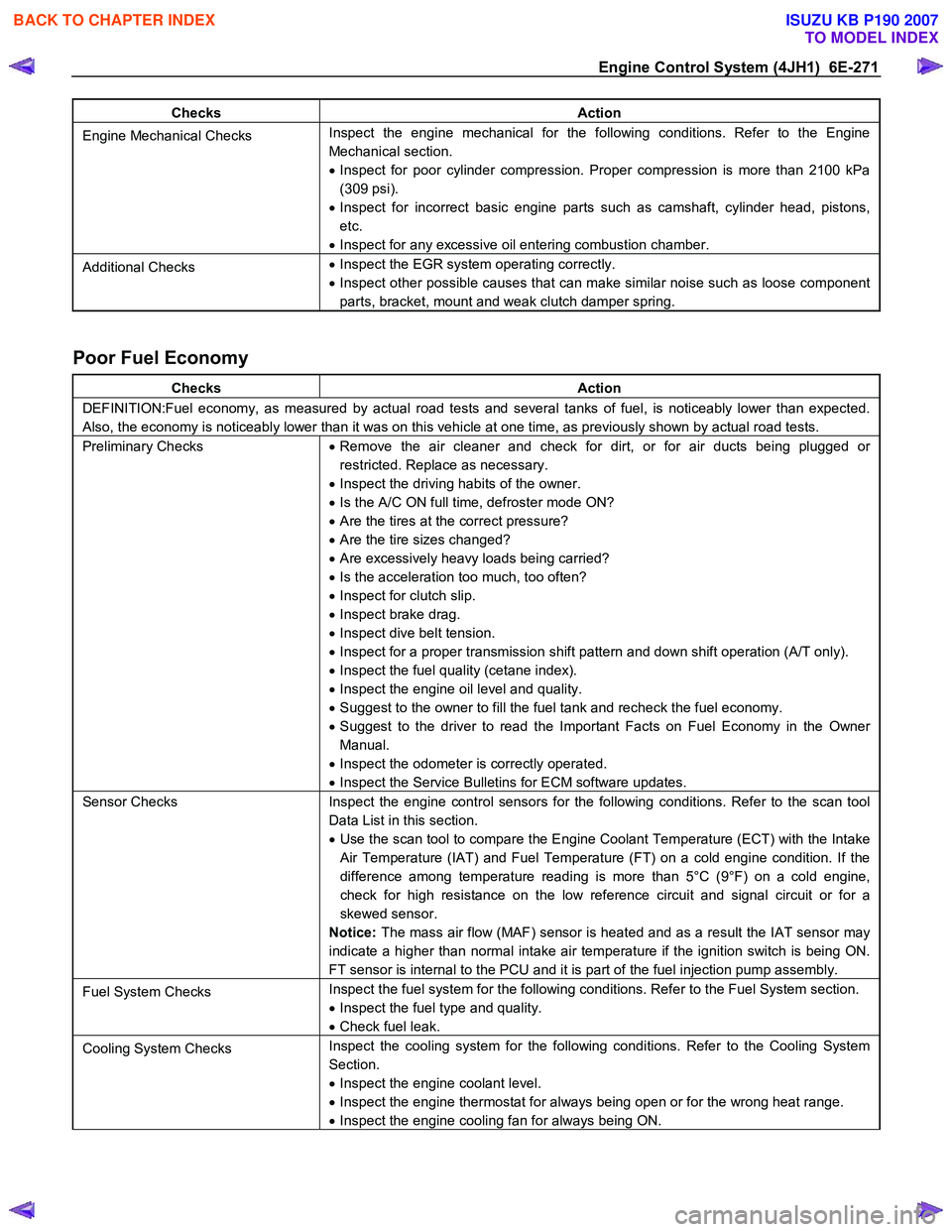
Engine Control System (4JH1) 6E-271
Checks Action
Engine Mechanical Checks Inspect the engine mechanical for the following conditions. Refer to the Engine
Mechanical section.
• Inspect for poor cylinder compression. Proper compression is more than 2100 kPa
(309 psi).
• Inspect for incorrect basic engine parts such as camshaft, cylinder head, pistons,
etc.
• Inspect for any excessive oil entering combustion chamber.
Additional Checks •
Inspect the EGR system operating correctly.
• Inspect other possible causes that can make similar noise such as loose component
parts, bracket, mount and weak clutch damper spring.
Poor Fuel Economy
Checks Action
DEFINITION:Fuel economy, as measured by actual road tests and several tanks of fuel, is noticeably lower than expected.
Also, the economy is noticeably lower than it was on this vehicle at one time, as previously shown by actual road tests.
Preliminary Checks • Remove the air cleaner and check for dirt, or for air ducts being plugged or
restricted. Replace as necessary.
• Inspect the driving habits of the owner.
• Is the A/C ON full time, defroster mode ON?
• Are the tires at the correct pressure?
• Are the tire sizes changed?
• Are excessively heavy loads being carried?
• Is the acceleration too much, too often?
• Inspect for clutch slip.
• Inspect brake drag.
• Inspect dive belt tension.
• Inspect for a proper transmission shift pattern and down shift operation (A/T only).
• Inspect the fuel quality (cetane index).
• Inspect the engine oil level and quality.
• Suggest to the owner to fill the fuel tank and recheck the fuel economy.
• Suggest to the driver to read the Important Facts on Fuel Economy in the Owner
Manual.
• Inspect the odometer is correctly operated.
• Inspect the Service Bulletins for ECM software updates.
Sensor Checks Inspect the engine control sensors for the following conditions. Refer to the scan tool
Data List in this section.
• Use the scan tool to compare the Engine Coolant Temperature (ECT) with the Intake
Air Temperature (IAT) and Fuel Temperature (FT) on a cold engine condition. If the
difference among temperature reading is more than 5°C (9°F) on a cold engine,
check for high resistance on the low reference circuit and signal circuit or for a
skewed sensor.
Notice: The mass air flow (MAF) sensor is heated and as a result the IAT sensor may
indicate a higher than normal intake air temperature if the ignition switch is being ON.
FT sensor is internal to the PCU and it is part of the fuel injection pump assembly.
Fuel System Checks Inspect the fuel system for the following conditions. Refer to the Fuel System section.
• Inspect the fuel type and quality.
• Check fuel leak.
Cooling System Checks Inspect the cooling system for the following conditions. Refer to the Cooling System
Section.
• Inspect the engine coolant level.
• Inspect the engine thermostat for always being open or for the wrong heat range.
• Inspect the engine cooling fan for always being ON.
BACK TO CHAPTER INDEX
TO MODEL INDEX
ISUZU KB P190 2007
Page 1306 of 6020
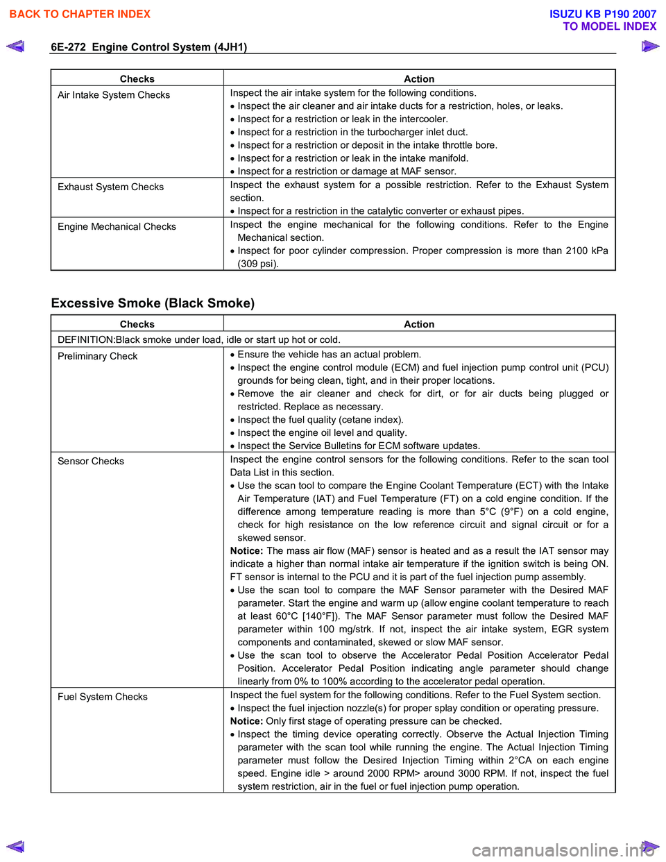
6E-272 Engine Control System (4JH1)
Checks Action
Air Intake System Checks Inspect the air intake system for the following conditions.
• Inspect the air cleaner and air intake ducts for a restriction, holes, or leaks.
• Inspect for a restriction or leak in the intercooler.
• Inspect for a restriction in the turbocharger inlet duct.
• Inspect for a restriction or deposit in the intake throttle bore.
• Inspect for a restriction or leak in the intake manifold.
• Inspect for a restriction or damage at MAF sensor.
Exhaust System Checks Inspect the exhaust system for a possible restriction. Refer to the Exhaust System
section.
• Inspect for a restriction in the catalytic converter or exhaust pipes.
Engine Mechanical Checks Inspect the engine mechanical for the following conditions. Refer to the Engine
Mechanical section.
• Inspect for poor cylinder compression. Proper compression is more than 2100 kPa
(309 psi).
Excessive Smoke (Black Smoke)
Checks Action
DEFINITION:Black smoke under load, idle or start up hot or cold.
Preliminary Check •
Ensure the vehicle has an actual problem.
• Inspect the engine control module (ECM) and fuel injection pump control unit (PCU)
grounds for being clean, tight, and in their proper locations.
• Remove the air cleaner and check for dirt, or for air ducts being plugged or
restricted. Replace as necessary.
• Inspect the fuel quality (cetane index).
• Inspect the engine oil level and quality.
• Inspect the Service Bulletins for ECM software updates.
Sensor Checks Inspect the engine control sensors for the following conditions. Refer to the scan tool
Data List in this section.
• Use the scan tool to compare the Engine Coolant Temperature (ECT) with the Intake
Air Temperature (IAT) and Fuel Temperature (FT) on a cold engine condition. If the
difference among temperature reading is more than 5°C (9°F) on a cold engine,
check for high resistance on the low reference circuit and signal circuit or for a
skewed sensor.
Notice: The mass air flow (MAF) sensor is heated and as a result the IAT sensor may
indicate a higher than normal intake air temperature if the ignition switch is being ON.
FT sensor is internal to the PCU and it is part of the fuel injection pump assembly.
• Use the scan tool to compare the MAF Sensor parameter with the Desired MAF
parameter. Start the engine and warm up (allow engine coolant temperature to reach
at least 60°C [140°F]). The MAF Sensor parameter must follow the Desired MAF
parameter within 100 mg/strk. If not, inspect the air intake system, EGR system
components and contaminated, skewed or slow MAF sensor.
• Use the scan tool to observe the Accelerator Pedal Position Accelerator Pedal
Position. Accelerator Pedal Position indicating angle parameter should change
linearly from 0% to 100% according to the accelerator pedal operation.
Fuel System Checks Inspect the fuel system for the following conditions. Refer to the Fuel System section.
• Inspect the fuel injection nozzle(s) for proper splay condition or operating pressure.
Notice: Only first stage of operating pressure can be checked.
• Inspect the timing device operating correctly. Observe the Actual Injection Timing
parameter with the scan tool while running the engine. The Actual Injection Timing
parameter must follow the Desired Injection Timing within 2°CA on each engine
speed. Engine idle > around 2000 RPM> around 3000 RPM. If not, inspect the fuel
system restriction, air in the fuel or fuel injection pump operation.
BACK TO CHAPTER INDEX
TO MODEL INDEX
ISUZU KB P190 2007
Page 1307 of 6020
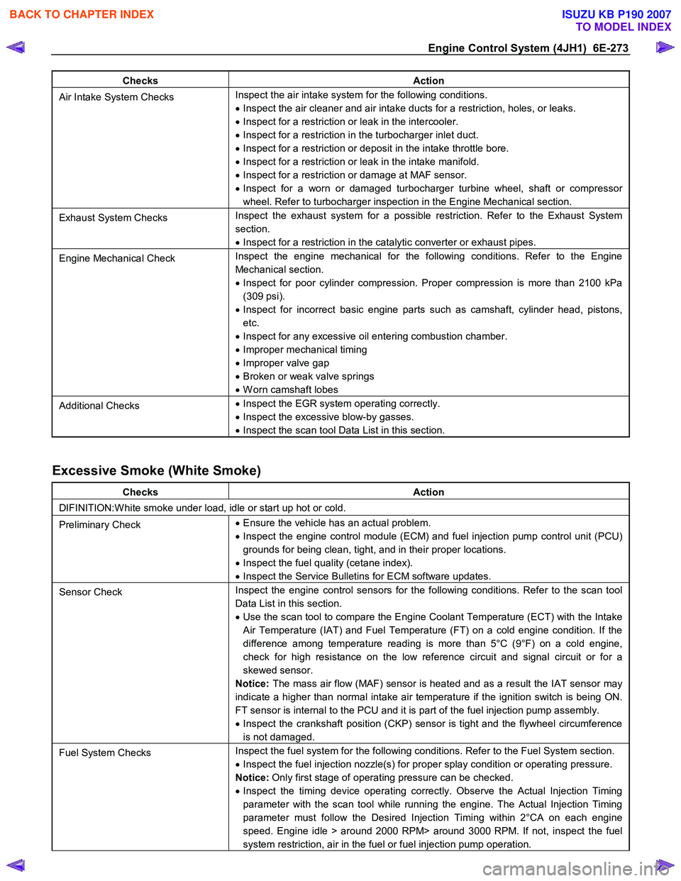
Engine Control System (4JH1) 6E-273
Checks Action
Air Intake System Checks Inspect the air intake system for the following conditions.
• Inspect the air cleaner and air intake ducts for a restriction, holes, or leaks.
• Inspect for a restriction or leak in the intercooler.
• Inspect for a restriction in the turbocharger inlet duct.
• Inspect for a restriction or deposit in the intake throttle bore.
• Inspect for a restriction or leak in the intake manifold.
• Inspect for a restriction or damage at MAF sensor.
• Inspect for a worn or damaged turbocharger turbine wheel, shaft or compressor
wheel. Refer to turbocharger inspection in the Engine Mechanical section.
Exhaust System Checks Inspect the exhaust system for a possible restriction. Refer to the Exhaust System
section.
• Inspect for a restriction in the catalytic converter or exhaust pipes.
Engine Mechanical Check Inspect the engine mechanical for the following conditions. Refer to the Engine
Mechanical section.
• Inspect for poor cylinder compression. Proper compression is more than 2100 kPa
(309 psi).
• Inspect for incorrect basic engine parts such as camshaft, cylinder head, pistons,
etc.
• Inspect for any excessive oil entering combustion chamber.
• Improper mechanical timing
• Improper valve gap
• Broken or weak valve springs
• W orn camshaft lobes
Additional Checks •
Inspect the EGR system operating correctly.
• Inspect the excessive blow-by gasses.
• Inspect the scan tool Data List in this section.
Excessive Smoke (White Smoke)
Checks Action
DIFINITION:W hite smoke under load, idle or start up hot or cold.
Preliminary Check •
Ensure the vehicle has an actual problem.
• Inspect the engine control module (ECM) and fuel injection pump control unit (PCU)
grounds for being clean, tight, and in their proper locations.
• Inspect the fuel quality (cetane index).
• Inspect the Service Bulletins for ECM software updates.
Sensor Check Inspect the engine control sensors for the following conditions. Refer to the scan tool
Data List in this section.
• Use the scan tool to compare the Engine Coolant Temperature (ECT) with the Intake
Air Temperature (IAT) and Fuel Temperature (FT) on a cold engine condition. If the
difference among temperature reading is more than 5°C (9°F) on a cold engine,
check for high resistance on the low reference circuit and signal circuit or for a
skewed sensor.
Notice: The mass air flow (MAF) sensor is heated and as a result the IAT sensor may
indicate a higher than normal intake air temperature if the ignition switch is being ON.
FT sensor is internal to the PCU and it is part of the fuel injection pump assembly.
• Inspect the crankshaft position (CKP) sensor is tight and the flywheel circumference
is not damaged.
Fuel System Checks Inspect the fuel system for the following conditions. Refer to the Fuel System section.
• Inspect the fuel injection nozzle(s) for proper splay condition or operating pressure.
Notice: Only first stage of operating pressure can be checked.
• Inspect the timing device operating correctly. Observe the Actual Injection Timing
parameter with the scan tool while running the engine. The Actual Injection Timing
parameter must follow the Desired Injection Timing within 2°CA on each engine
speed. Engine idle > around 2000 RPM> around 3000 RPM. If not, inspect the fuel
system restriction, air in the fuel or fuel injection pump operation.
BACK TO CHAPTER INDEX
TO MODEL INDEX
ISUZU KB P190 2007
Page 1327 of 6020
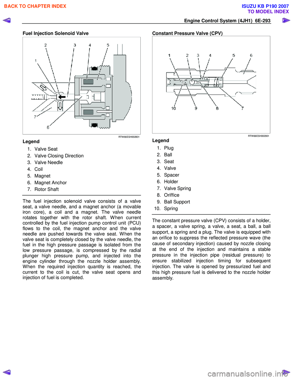
Engine Control System (4JH1) 6E-293
Fuel Injection Solenoid Valve
RTW 66ESH002801
Legend
1. Valve Seat
2. Valve Closing Direction
3. Valve Needle
4. Coil
5. Magnet
6. Magnet Anchor
7. Rotor Shaft
The fuel injection solenoid valve consists of a valve
seat, a valve needle, and a magnet anchor (a movable
iron core), a coil and a magnet. The valve needle
rotates together with the rotor shaft. W hen current
controlled by the fuel injection pump control unit (PCU)
flows to the coil, the magnet anchor and the valve
needle are pushed towards the valve seat. W hen the
valve seat is completely closed by the valve needle, the
fuel in the high pressure passage is isolated from the
low pressure passage, is compressed by the radial
plunger high pressure pump, and injected into the
engine cylinder through the nozzle holder assembly.
W hen the required injection quantity is reached, the
current to the coil is cut, the valve seat opens and
injection of fuel is completed.
Constant Pressure Valve (CPV)
RTW 66ESH002901
Legend
1. Plug
2. Ball
3. Seat
4. Valve
5. Spacer
6. Holder
7. Valve Spring
8. Oriffice
9. Ball Support
10. Spring
The constant pressure valve (CPV) consists of a holder,
a spacer, a valve spring, a valve, a seat, a ball, a ball
support, a spring and a plug. The valve is equipped with
an orifice to suppress the reflected pressure wave (the
cause of secondary injection) caused by nozzle closing
at the end of the injection and maintains a stable
pressure in the injection pipe (residual pressure) to
ensure stabilized injection timing for subsequent
injection. The valve is opened by pressurized fuel and
this high pressure fuel is delivered to the nozzle holde
r
assembly.
BACK TO CHAPTER INDEX
TO MODEL INDEX
ISUZU KB P190 2007
Page 1329 of 6020
Engine Control System (4JH1) 6E-295
The timing control valve (TCV) acts as a variable
throttle, using the rapid opening and closing (cycling)
of the valve needle in the TCV.
At normal operation,
the TCV controls the pressure acting on the annula
r
chamber so that the hydraulic stopper cam move to
any position, from the retard position to the advance
position. At this time, the duty ratio is set by the fuel
injection pump control unit (PCU).
When control current flows to the TCV coil, the valve
needle opens and the fuel annular chamber flows
through the orifice to the feed pump inlet.
Consequently, the pressure of the annular chambe
r
decreases and the hydraulic stopper is moved to the
retard side.
When control current to the TCV coil is cut, the valve
needle closes and the return passage is closed.
Consequently, the pressure of the annular chambe
r
increases and the hydraulic stopper is moved to the
advance side.
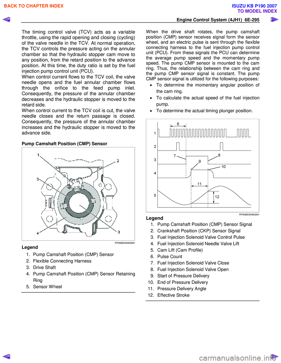
Pump Camshaft Position (CMP) Sensor
RTW 66ESH003301
Legend
1. Pump Camshaft Position (CMP) Sensor
2. Flexible Connecting Harness
3. Drive Shaft
4. Pump Camshaft Position (CMP) Sensor Retaining Ring
5. Sensor W heel
W hen the drive shaft rotates, the pump camshaft
position (CMP) sensor receives signal form the senso
r
wheel, and an electric pulse is sent through the flexible
connecting harness to the fuel injection pump control
unit (PCU). From these signals the PCU can determine
the average pump speed and the momentary pump
speed. The pump CMP sensor is mounted to the cam
ring. Thus, the relationship between the cam ring and
the pump CMP sensor signal is constant. The pump
CMP sensor signal is utilized for the following purposes:
• To determine the momentary angular position o
f
the cam ring.
• To calculate the actual speed of the fuel injection
pump.
• To determine the actual timing plunger position.
RTW 66ESH003401Legend
1. Pump Camshaft Position (CMP) Sensor Signal
2. Crankshaft Position (CKP) Sensor Signal
3. Fuel Injection Solenoid Valve Control Pulse
4. Fuel Injection Solenoid Needle Valve Lift
5. Cam Lift (Cam Profile)
6. Pulse Count
7. Fuel Injection Solenoid Valve Close
8. Fuel Injection Solenoid Valve Open
9. Start of Pressure Delivery
10. End of Pressure Delivery
11. Pressure Delivery Angle
12. Effective Stroke
BACK TO CHAPTER INDEX
TO MODEL INDEX
ISUZU KB P190 2007
Page 1365 of 6020
ENGINE MECHANICAL (4JK1/4JJ1) 6A-5
EGR system
Based upon data, including water temperature, engine
speeds or engine loads, it is controlled via Engine
Control Module (ECM) to purify exhaust by recycling
part of it.
Its main components include an EGR valve, an EGR
cooler and various sensors.
Connecting rod cap bolt
The angular tightening method of the connecting rod
cap bolt further increases reliability and durability.
Fuel rail-type electronic control injection system
The fuel rail-type electronic control injection system is
composed of a fuel supply pump that sets the target
pressure of high-pressure fuel and supply it, a fuel rail
that measures such high-pressure fuel and a fuel
injector that turns it into a fine spray and injects it. Each
is controlled via ECM based upon various signals, while
injection timing or fuel injection quantity is controlled
under every possible driving condition.
Fuel injector
The fuel injector is a 6-hole nozzle that adjusts fuel
injection quantity or injection timing by opening o
r
closing an electromagnetic valve on the head of the fuel
injector.
ECM corrects the dispersion of fuel injection quantit
y
between fuel injector according to ID code data in
memory. At the replacement of fuel injector, ID code
data should be stored in ECM.
Fuel filter with sedimenter
It is a fuel filter with sedimenter that gets rid of water by
making use of the difference in specific gravity between
light oil and water, which comes with an indicator that
notifies you that it is filled with water.
Preheating system
The preheating system consists of the ECM, the glow
relay, glow plugs and the glow indicator lamp. The
preheating system is operated when the engine coolant
temperature is low, and makes the engine easy to start.
Lubrication system
It is an oil filter with full-flow bypass, which uses a
water-cool oil cooler and oil jet to cool the piston.
Functional inspection
Inspection/adjustment of valve clearance 1. Inspection of valve clearance
• Remove the fuel injector harness assembly.
• Remove the leak off hose.
• Remove the cylinder head cover.
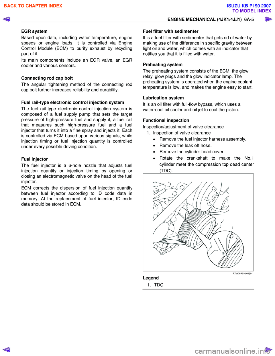
• Rotate the crankshaft to make the No.1
cylinder meet the compression top dead cente
r
(TDC).
RTW 76ASH001301
Legend
1. TDC
BACK TO CHAPTER INDEX
TO MODEL INDEX
ISUZU KB P190 2007
Page 1372 of 6020
6A-12 ENGINE MECHANICAL (4JK1/4JJ1)
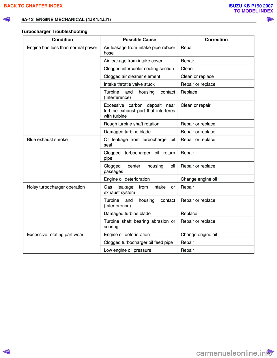
Turbocharger Troubleshooting
Condition Possible Cause Correction
Air leakage from intake pipe rubber
hose Repair
Air leakage from intake cover Repair
Clogged intercooler cooling section Clean
Clogged air cleaner element Clean or replace
Intake throttle valve stuck
Repair or replace
Turbine and housing contact
(Interference) Replace
Excessive carbon deposit near
turbine exhaust port that interferes
with turbine Clean or repair
Rough turbine shaft rotation Repair or replace
Engine has less than normal power
Damaged turbine blade Repair or replace
Oil leakage from turbocharger oil
seal Repair or replace
Clogged turbocharger oil return
pipe Repair
Clogged center housing oil
passages Repair or replace
Blue exhaust smoke
Engine oil deterioration Change engine oil
Gas leakage from intake or
exhaust system Repair
Turbine and housing contact
(Interference) Repair or replace
Damaged turbine blade
Replace
Noisy turbocharger operation
Turbine shaft bearing abrasion or
scoring Repair or replace
Engine oil deterioration
Change engine oil
Clogged turbocharger oil feed pipe Repair
Excessive rotating part wear
Low engine oil pressure Repair
BACK TO CHAPTER INDEX
TO MODEL INDEX
ISUZU KB P190 2007
Page 1373 of 6020
ENGINE MECHANICAL (4JK1/4JJ1) 6A-13
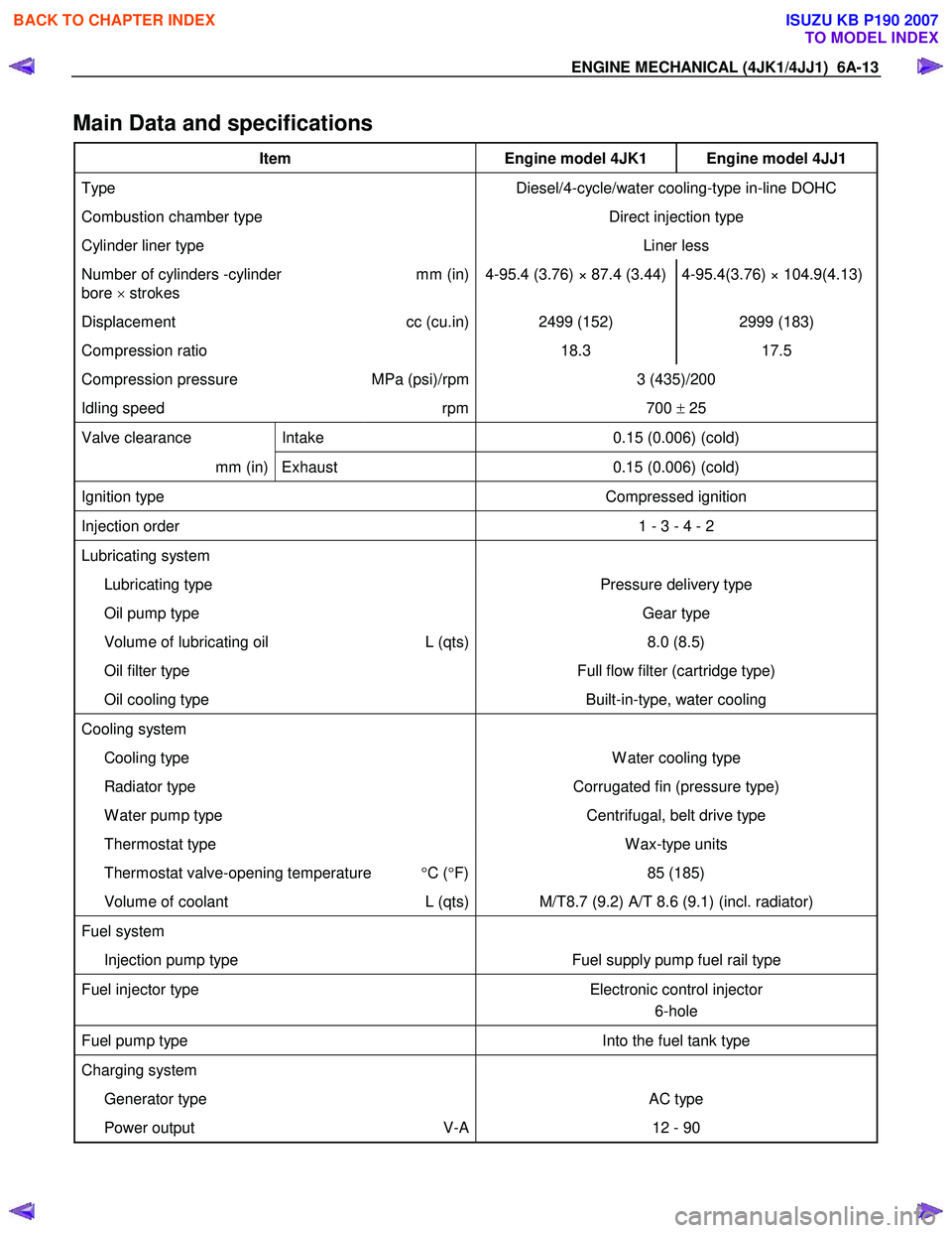
Main Data and specifications
Item Engine model 4JK1 Engine model 4JJ1
Type Diesel/4-cycle/water cooling-type in-line DOHC
Combustion chamber type Direct injection type
Cylinder liner type Liner less
Number of cylinders -cylinder
bore × strokes mm (in) 4-95.4 (3.76) × 87.4 (3.44) 4-95.4(3.76) × 104.9(4.13)
Displacement
cc (cu.in) 2499 (152) 2999 (183)
Compression ratio 18.3 17.5
Compression pressure MPa (psi)/rpm 3 (435)/200
Idling speed rpm 700 ± 25
Valve clearance Intake 0.15 (0.006) (cold)
mm (in) Exhaust 0.15 (0.006) (cold)
Ignition type Compressed ignition
Injection order 1 - 3 - 4 - 2
Lubricating system
Lubricating type Pressure delivery type
Oil pump type Gear type
Volume of lubricating oil L (qts) 8.0 (8.5)
Oil filter type Full flow filter (cartridge type)
Oil cooling type Built-in-type, water cooling
Cooling system
Cooling type W ater cooling type
Radiator type Corrugated fin (pressure type)
W ater pump type Centrifugal, belt drive type
Thermostat type W ax-type units
Thermostat valve-opening temperature °C ( °F) 85 (185)
Volume of coolant L (qts) M/T8.7 (9.2) A/T 8.6 (9.1) (incl. radiator)
Fuel system
Injection pump type Fuel supply pump fuel rail type
Fuel injector type Electronic control injector
6-hole
Fuel pump type Into the fuel tank type
Charging system
Generator type AC type
Power output V-A 12 - 90
BACK TO CHAPTER INDEX
TO MODEL INDEX
ISUZU KB P190 2007