2007 ISUZU KB P190 low oil pressure
[x] Cancel search: low oil pressurePage 832 of 6020

ENGINE MECHANICAL 6A – 27
111R300001
COOLING SYSTEM
Coolant Level
Check the coolant level and replenish the radiator reserve
tank as necessary.
If the coolant level falls below the “MIN” line, carefully
check the cooling system for leakage. Then add enough
coolant to bring the level up to the “MAX” line.
Engine coolant Filling up procedure
1. Make sure that the engine is cool.
Warning:
When the coolant is heated to a high temperature, be
sure not to loosen or remove the rediator cap.
Otherwise you might get scalded by hot vapor or
boiling water.
To open the radiator cap, put a piece of thick cloth on
the cap and loosen the cap slowly to reduce the
pressure when the coolant has become cooler.
2. Open rediator cap pour coolant up to filler neck
3. Pour coolant into reservoir tank up to “MAX” line
4. Tighten radiator cap and start the engine. After idling for 2 to 3 minutes, stop the engine and reopen radiator
cap. If the water level is lower, replenish.
5. After replenish the coolant tighten radiator cap, warm up the engine at about 2000 rpm. Set heater
adjustment to the highest temperature position, and let
the coolant circulate also into heater water system.
6. Check to see the thermometer, continuously idling 5 minutes and stop the engine.
7. W hen the engine has been cooled, check filler neck for water level and replenish if required. Should
extreme shortage of coolant is found, check the
coolant system and reservoir tank hose for leakage.
8. Pour coolant into the reservoir tank up to “MAX” line.
Engine Coolant Total Capacity Lit (U.S / UK gal)
4JA1 / TC 9.4 (2.5 / 2.1)
4JH1TC M/T: 10.1 (2.7 / 2.2)
A/T: 10.0 (2.6 / 2.2)
Mixing Ratio (Anti-Freeze Solution/W ater)
50 %
BACK TO CHAPTER INDEX
TO MODEL INDEX
ISUZU KB P190 2007
Page 844 of 6020

ENGINE MECHANICAL 6A – 39
18. Radiator 1) Drain the engine coolant.
2) Remove the reservoir hose.
3) Remove the upper and lower hose.
4) Remove the fan guide.
5) Remove the radiator.
19. Fan
P1010034
20. Air cleaner
1) Remove the MAF sensor connector (4JA1TC/4JH1TC) from air cleaner duct.
2) Remove the air cleaner duct and the air cleaner box from engine room.
3) Remove the two air ducts from inter cooler (4JA1TC/4JH1TC).
21. Power Steering Pump Loosen the power steering pump adjust plate bolt, then
remove the power steering pump assembly. Place the
power steering pump assembly along with piping on the
body side.
22. Air conditioner compressor 1) Remove air compressor magnet connector.
2) Remove the air conditioner compressor. Place the air conditioner compressor along with piping on the body
side.
23. Engine Control Cable Remove the engine control cable from its bracket
(4JA1TC/4JH1TC) or the injection pump (4JA1T(L)).
24. Vacuum Piping Remove the vacuum pipe from the vacuum pump, the
EGR valve, injection pump FICD (4JA1T(L)).
25. Engine Harness 1) Remove following connectors from engine.
• TPS connector
• Oil pressure switch connector
• Thermo switch connector
• Injection pump connector
• Engine earth
• Thermometer unit connector
• TDC sensor
2) Remove the clips fixing engine harness.
P1010009
BACK TO CHAPTER INDEX
TO MODEL INDEX
ISUZU KB P190 2007
Page 846 of 6020

ENGINE MECHANICAL 6A – 41
Coolant Replenishment
Warning:
When the coolant is heated to a high temperature, be
sure not to loosen or remove the rediator cap.
Otherwise you might get scalded by hot vapor or
boiling water.
To open the radiator cap, put a piece of thick cloth on
the cap and loosen the cap slowly to reduce the
pressure when the coolant has become cooler.
1. Open rediator cap pour coolant up to filler neck
2. Pour coolant into reservoir tank up to "MAX" line
3. Tighten radiator cap and start the engine. After idling for 2 to 3 minutes, stop the engine and reopen radiator
cap. If the water level is lower, replenish.
4. After replenish the coolant tighten radiator cap, warm up the engine at about 2000 rpm. Set heater
adjustment to the highest temperature position, and let
the coolant circulate also into heater water system.
5. Check to see the thermometer, continuously idling 5 minutes and stop the engine.
6. W hen the engine has been cooled, check filler neck for water level and replenish if required. Should extreme
shortage of coolant is found, check the coolant system
and reservoir tank hose for leakage.
7. Pour coolant into the reservoir tank up to "MAX" line.
Coolant Capacity lit (US/UK gal)
4JA1 / TC 9.4 (2.5 / 2.1)
4JH1TC M/T: 10.1 (2.7 / 2.2)
A/T: 10.0 (2.6 / 2.2)
Engine Warm-Up
After completing the required maintenance procedures,
start the engine and allow it to idle until it is warm.
Check the following:
1. Engine idling speed.
2. Engine noise level.
3. Engine lubricating system and cooling system. Carefully check for oil and coolant leakage.
4. Clutch engagement.
5. Transmission operation.
6. Indicator warning light operation.
BACK TO CHAPTER INDEX
TO MODEL INDEX
ISUZU KB P190 2007
Page 931 of 6020

6A – 126 ENGINE MECHANICAL
LUBRICATION SYSTEM
LUBRICATING OIL FLOW
1. Oil Pump Relief Valve Operating Pressure: 6.2 - 7.8 kg/cm
2 (608 – 764 kPa)
2. Regulating Valve Operating Pressure: 5.7 - 6.3 kg/cm2 (558.6 - 617.4 kPa)
3. Oil Cooler Relief Valve Opening Pressure: 2.8 - 3.4 kg/cm2 (270 – 330 kPa)
4. Oil Filter Relief Valve Opening Pressure: 0.8 - 1.2 kg/cm2 (78.4 - 117.6 kPa)
5. Oil Pressure Switch Operating Pressure: 0.3 - 0.5 kg/cm2 (29.4 - 49.0 kPa)
6. Regulating Valve: 1.8 - 2.2 kg/cm2 (176 – 216 kPa)
The 4J series engine has a full flow type lubricating system.
Lubricating oil is pumped from the oil pump to the cylinder body oil gallery through the oil cooler and the oil filter. It is
then delivered to the vital parts of the engine from the cylinder body oil gallery.
Oiling jets installed on the cylinder body spray engine oil to the piston backside faces to achieve maximum piston
cooling effect.
BACK TO CHAPTER INDEX
TO MODEL INDEX
ISUZU KB P190 2007
Page 952 of 6020

6B – 8 ENGINE COOLING
Draining and Refilling Cooling System
Before draining the cooling system, inspect the system and
perform any necessary service to ensure that it is clean, does
not leak and is in proper working order. The engine coolant
(EC) level should be between the “MIN" and “MAX" lines o
f
reserve tank when the engine is cold. If low, check for leakage
and add EC up to the “MAX" line.
There should not be any excessive deposit of rust or scales
around the radiator cap or radiator filler hole, and the EC
should also be free from oil.
Replace the EC if excessively dirty.
P1010064
1. Completely drain the cooling system by opening the drain
plug at the bottom of the radiator.
2. Remove the radiator cap.
WARNING: To avoid the danger of being burned, do not
remove the cap while the engine and radiator are still hot.
Scalding fluid and steam can be blown out unde
r
pressure.
3. Disconnect all hoses from the EC reserve tank.
Scrub and clean the inside of the reserve tank with soap and water. Flush it well with clean water, then drain it.
Install the reserve tank and hoses.
4. Refill the cooling system with the EC using a solution that is at least 50 percent antifreeze.
Procedure for filling with coolant (in case of full change)
• Make sure that the engine is cool.
• Open radiator cap pour coolant up to filler neck.
• Pour coolant into reservoir tank up to “MAX" line.
• Tighten radiator cap and start the engine. After idling for 2
to 3 minutes, stop the engine and reopen radiator cap. If the
water level is lower, replenish.
WARNING: When the coolant is heated to a high
temperature, be sure not to loosen or remove the radiato
r
cap. Otherwise you might get scalded by not vapor or
boiling water. To open the radiator cap, put a piece of
thick cloth on the cap and loosen the cap slowly to reduce
the pressure when the coolant has become cooler.
BACK TO CHAPTER INDEX
TO MODEL INDEX
ISUZU KB P190 2007
Page 1082 of 6020

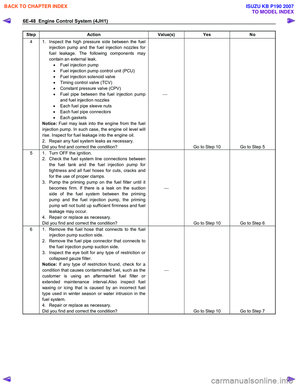
6E-48 Engine Control System (4JH1)
Step Action Value(s) Yes No
4 1. Inspect the high pressure side between the fuel
injection pump and the fuel injection nozzles for
fuel leakage. The following components may
contain an external leak. • Fuel injection pump
• Fuel injection pump control unit (PCU)
• Fuel injection solenoid valve
• Timing control valve (TCV)
• Constant pressure valve (CPV)
• Fuel pipe between the fuel injection pump
and fuel injection nozzles
• Each fuel pipe sleeve nuts
• Each fuel pipe connectors
• Each gaskets
Notice: Fuel may leak into the engine from the fuel
injection pump. In such case, the engine oil level will
rise. Inspect for fuel leakage into the engine oil.
2. Repair any fuel system leaks as necessary.
Did you find and correct the condition?
Go to Step 10 Go to Step 5
5 1. Turn OFF the ignition. 2. Check the fuel system line connections between the fuel tank and the fuel injection pump for
tightness and all fuel hoses for cuts, cracks and
for the use of proper clamps.
3. Pump the priming pump on the fuel filter until it becomes firm. If there is a leak on the suction
side of the fuel system between the priming
pump and the fuel injection pump, the priming
pump will not build up sufficient firmness and fuel
leakage may occur.
4. Repair or replace as necessary.
Did you find and correct the condition?
Go to Step 10 Go to Step 6
6 1. Remove the fuel hose that connects to the fuel injection pump suction side.
2. Remove the fuel pipe connector that connects to the fuel injection pump suction side.
3. Inspect the eye bolt for any type of restriction or collapsed gauze filter.
Notice: If any type of restriction found, check for a
condition that causes contaminated fuel, such as the
customer is using an aftermarket fuel filter or
extended maintenance interval.Also inspect fuel
waxing or icing that is caused by an incorrect fuel
type used in winter season or water intrusion in the
fuel system.
4. Repair or replace as necessary.
Did you find and correct the condition?
Go to Step 10 Go to Step 7
BACK TO CHAPTER INDEX
TO MODEL INDEX
ISUZU KB P190 2007
Page 1153 of 6020

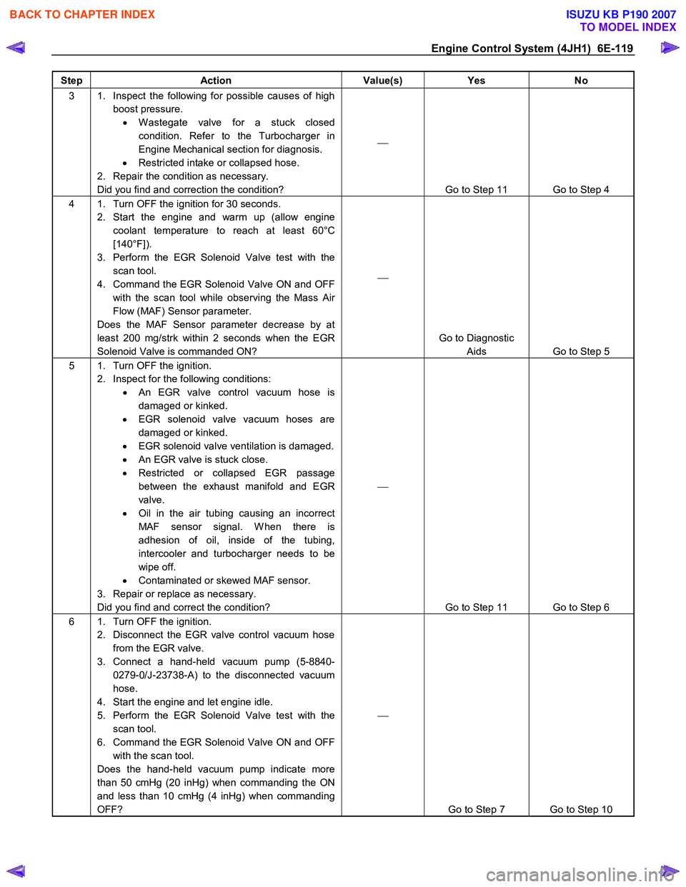
Engine Control System (4JH1) 6E-119
Step Action Value(s) Yes No
3 1. Inspect the following for possible causes of high
boost pressure. • W astegate valve for a stuck closed
condition. Refer to the Turbocharger in
Engine Mechanical section for diagnosis.
• Restricted intake or collapsed hose.
2. Repair the condition as necessary.
Did you find and correction the condition?
Go to Step 11 Go to Step 4
4 1. Turn OFF the ignition for 30 seconds. 2. Start the engine and warm up (allow engine coolant temperature to reach at least 60°C
[140°F]).
3. Perform the EGR Solenoid Valve test with the scan tool.
4. Command the EGR Solenoid Valve ON and OFF with the scan tool while observing the Mass Air
Flow (MAF) Sensor parameter.
Does the MAF Sensor parameter decrease by at
least 200 mg/strk within 2 seconds when the EGR
Solenoid Valve is commanded ON?
Go to Diagnostic Aids Go to Step 5
5 1. Turn OFF the ignition. 2. Inspect for the following conditions: • An EGR valve control vacuum hose is
damaged or kinked.
• EGR solenoid valve vacuum hoses are
damaged or kinked.
• EGR solenoid valve ventilation is damaged.
• An EGR valve is stuck close.
• Restricted or collapsed EGR passage
between the exhaust manifold and EGR
valve.
• Oil in the air tubing causing an incorrect
MAF sensor signal. W hen there is
adhesion of oil, inside of the tubing,
intercooler and turbocharger needs to be
wipe off.
• Contaminated or skewed MAF sensor.
3. Repair or replace as necessary.
Did you find and correct the condition?
Go to Step 11 Go to Step 6
6 1. Turn OFF the ignition. 2. Disconnect the EGR valve control vacuum hose from the EGR valve.
3. Connect a hand-held vacuum pump (5-8840- 0279-0/J-23738-A) to the disconnected vacuum
hose.
4. Start the engine and let engine idle.
5. Perform the EGR Solenoid Valve test with the scan tool.
6. Command the EGR Solenoid Valve ON and OFF with the scan tool.
Does the hand-held vacuum pump indicate more
than 50 cmHg (20 inHg) when commanding the ON
and less than 10 cmHg (4 inHg) when commanding
OFF?
Go to Step 7 Go to Step 10
BACK TO CHAPTER INDEX
TO MODEL INDEX
ISUZU KB P190 2007
Page 1181 of 6020

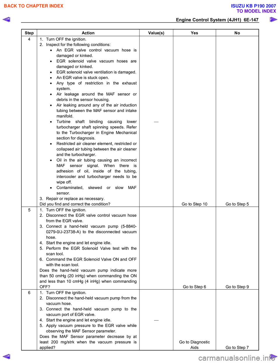
Engine Control System (4JH1) 6E-147
Step Action Value(s) Yes No
4 1. Turn OFF the ignition.
2. Inspect for the following conditions: • An EGR valve control vacuum hose is
damaged or kinked.
• EGR solenoid valve vacuum hoses are
damaged or kinked.
• EGR solenoid valve ventilation is damaged.
• An EGR valve is stuck open.
• Any type of restriction in the exhaust
system.
• Air leakage around the MAF sensor or
debris in the sensor housing.
• Air leaking around any of the air induction
tubing between the MAF sensor and intake
manifold.
• Turbine shaft binding causing lower
turbocharger shaft spinning speeds. Refer
to the Turbocharger in Engine Mechanical
section for diagnosis.
• Restricted air cleaner element, restricted or
collapsed air tubing between the air cleaner
and the turbocharger.
• Oil in the air tubing causing an incorrect
MAF sensor signal. W hen there is
adhesion of oil, inside of the tubing,
intercooler and turbocharger needs to be
wipe off.
• Contaminated, skewed or slow MAF
sensor.
3. Repair or replace as necessary.
Did you find and correct the condition?
Go to Step 10 Go to Step 5
5 1. Turn OFF the ignition. 2. Disconnect the EGR valve control vacuum hose from the EGR valve.
3. Connect a hand-held vacuum pump (5-8840- 0279-0/J-23738-A) to the disconnected vacuum
hose.
4. Start the engine and let engine idle.
5. Perform the EGR Solenoid Valve test with the scan tool.
6. Command the EGR Solenoid Valve ON and OFF with the scan tool.
Does the hand-held vacuum pump indicate more
than 50 cmHg (20 inHg) when commanding the ON
and less than 10 cmHg (4 inHg) when commanding
OFF?
Go to Step 6 Go to Step 9
6 1. Turn OFF the ignition. 2. Disconnect the hand-held vacuum pump from the vacuum hose.
3. Connect the hand-held vacuum pump to the vacuum port of EGR valve.
4. Start the engine and let engine idle.
5. Apply vacuum pressure to the EGR valve while observing the MAF Sensor parameter.
Does the MAF Sensor parameter decrease by at
least 200 mg/strk when the vacuum pressure is
applied?
Go to Diagnostic Aids Go to Step 7
BACK TO CHAPTER INDEX
TO MODEL INDEX
ISUZU KB P190 2007