2007 ISUZU KB P190 coolant temperature
[x] Cancel search: coolant temperaturePage 1128 of 6020
6E-94 Engine Control System (4JH1)
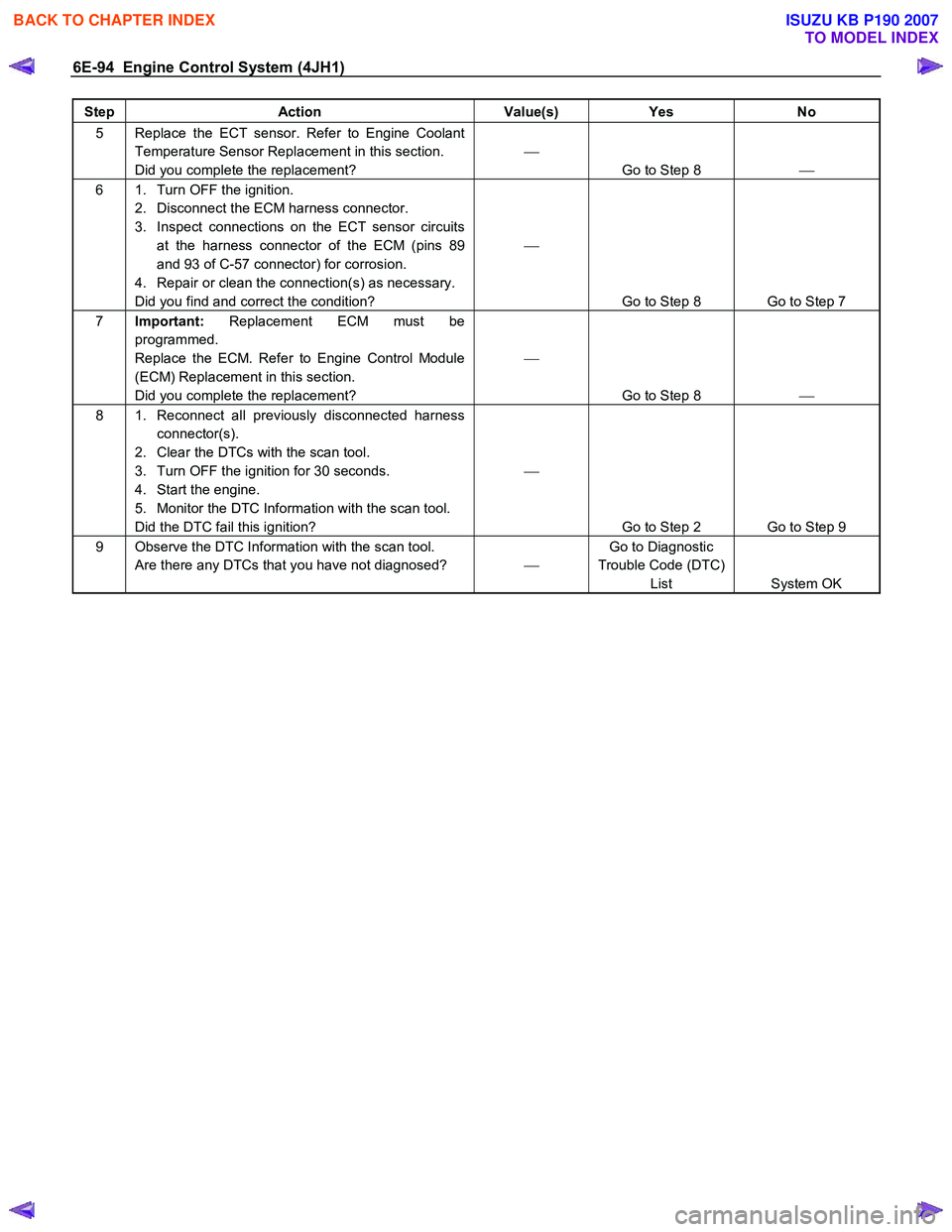
Step Action Value(s) Yes No
5 Replace the ECT sensor. Refer to Engine Coolant
Temperature Sensor Replacement in this section.
Did you complete the replacement?
Go to Step 8
6 1. Turn OFF the ignition.
2. Disconnect the ECM harness connector.
3. Inspect connections on the ECT sensor circuits at the harness connector of the ECM (pins 89
and 93 of C-57 connector) for corrosion.
4. Repair or clean the connection(s) as necessary.
Did you find and correct the condition?
Go to Step 8 Go to Step 7
7 Important: Replacement ECM must be
programmed.
Replace the ECM. Refer to Engine Control Module
(ECM) Replacement in this section.
Did you complete the replacement?
Go to Step 8
8 1. Reconnect all previously disconnected harness
connector(s).
2. Clear the DTCs with the scan tool.
3. Turn OFF the ignition for 30 seconds.
4. Start the engine.
5. Monitor the DTC Information with the scan tool.
Did the DTC fail this ignition?
Go to Step 2 Go to Step 9
9 Observe the DTC Information with the scan tool. Are there any DTCs that you have not diagnosed? Go to Diagnostic
Trouble Code (DTC) List System OK
BACK TO CHAPTER INDEX
TO MODEL INDEX
ISUZU KB P190 2007
Page 1141 of 6020
Engine Control System (4JH1) 6E-107
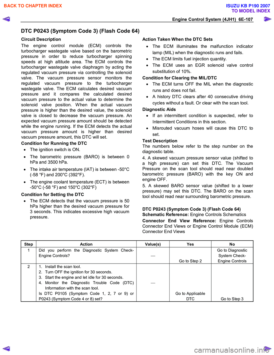
DTC P0243 (Symptom Code 3) (Flash Code 64)
Circuit Description
The engine control module (ECM) controls the
turbocharger wastegate valve based on the barometric
pressure in order to reduce turbocharger spinning
speeds at high altitude area. The ECM controls the
turbocharger wastegate valve diaphragm by acting the
regulated vacuum pressure via controlling the solenoid
valve. The vacuum pressure sensor monitors the
regulated vacuum pressure to the turbocharge
r
wastegate valve. The ECM calculates desired vacuum
pressure and it compares the calculated desired
vacuum pressure to the actual value to determine the
solenoid valve position. W hen the actual vacuum
pressure is higher than the desired value, the solenoid
valve is closed to decrease the vacuum pressure. An
expected vacuum pressure amount should be detected
while the engine running. If the ECM detects the actual
vacuum pressure amount is higher than desired
vacuum pressure amount, this DTC will set.
Condition for Running the DTC
• The ignition switch is ON.
• The barometric pressure (BARO) is between 0
hPa and 3500 hPa.
• The intake air temperature (IAT) is between -50°C
(-58 °F) and 200°C (392°F).
• The engine coolant temperature (ECT) is between
-50°C (-58 °F) and 150°C (302°F)
Condition for Setting the DTC
• The ECM detects that the vacuum pressure is 50
hPa higher than the desired vacuum pressure for
3 seconds. This indicates excessive high vacuum
pressure.
Action Taken When the DTC Sets
• The ECM illuminates the malfunction indicato
r
lamp (MIL) when the diagnostic runs and fails.
• The ECM limits fuel injection quantity.
• The ECM uses an EGR solenoid valve control
substitution of 10%.
Condition for Clearing the MIL/DTC
• The ECM turns OFF the MIL when the diagnostic
runs and does not fail.
• A history DTC clears after 40 consecutive driving
cycles without a fault. Or clear with the scan tool.
Diagnostic Aids
• If an intermittent condition is suspected, refer to
Intermittent Conditions in this section.
• Misrouted vacuum hoses will cause this DTC to
set.
Test Description
The numbers below refer to the step number on the
diagnostic table.
4. A skewed vacuum pressure sensor value (shifted to
a high pressure) can set this DTC. The Vacuum
Pressure on the scan tool should read near doubled
barometric pressure (BARO) with the key ON and
engine OFF.
5. A skewed BARO sensor value (shifted to a lowe
r
pressure) may set this DTC. The BARO on the scan
tool should read near surrounding barometric pressure.
DTC P0243 (Symptom Code 3) (Flash Code 64)
Schematic Reference: Engine Controls Schematics
Connector End View Reference: Engine Controls
Connector End Views or Engine Control Module (ECM)
Connector End Views
Step Action Value(s) Yes No
1 Did you perform the Diagnostic System Check-
Engine Controls?
Go to Step 2 Go to Diagnostic
System Check-
Engine Controls
2 1. Install the scan tool. 2. Turn OFF the ignition for 30 seconds.
3. Start the engine and let idle for 30 seconds.
4. Monitor the Diagnostic Trouble Code (DTC) Information with the scan tool.
Is DTC P0105 (Symptom Code 1, 2, 7 or 9) or
P0243 (Symptom Code 4 or 8) set?
Go to Applicable DTC Go to Step 3
BACK TO CHAPTER INDEX
TO MODEL INDEX
ISUZU KB P190 2007
Page 1148 of 6020
6E-114 Engine Control System (4JH1)
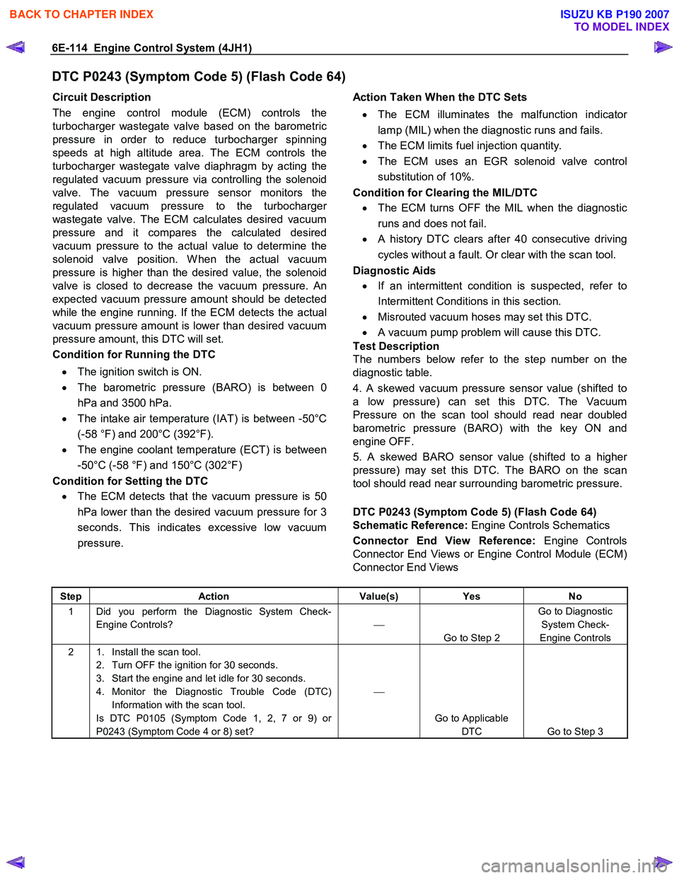
DTC P0243 (Symptom Code 5) (Flash Code 64)
Circuit Description
The engine control module (ECM) controls the
turbocharger wastegate valve based on the barometric
pressure in order to reduce turbocharger spinning
speeds at high altitude area. The ECM controls the
turbocharger wastegate valve diaphragm by acting the
regulated vacuum pressure via controlling the solenoid
valve. The vacuum pressure sensor monitors the
regulated vacuum pressure to the turbocharge
r
wastegate valve. The ECM calculates desired vacuum
pressure and it compares the calculated desired
vacuum pressure to the actual value to determine the
solenoid valve position. W hen the actual vacuum
pressure is higher than the desired value, the solenoid
valve is closed to decrease the vacuum pressure. An
expected vacuum pressure amount should be detected
while the engine running. If the ECM detects the actual
vacuum pressure amount is lower than desired vacuum
pressure amount, this DTC will set.
Condition for Running the DTC
• The ignition switch is ON.
• The barometric pressure (BARO) is between 0
hPa and 3500 hPa.
• The intake air temperature (IAT) is between -50°C
(-58 °F) and 200°C (392°F).
• The engine coolant temperature (ECT) is between
-50°C (-58 °F) and 150°C (302°F)
Condition for Setting the DTC
• The ECM detects that the vacuum pressure is 50
hPa lower than the desired vacuum pressure for 3
seconds. This indicates excessive low vacuum
pressure.
Action Taken When the DTC Sets
• The ECM illuminates the malfunction indicato
r
lamp (MIL) when the diagnostic runs and fails.
• The ECM limits fuel injection quantity.
• The ECM uses an EGR solenoid valve control
substitution of 10%.
Condition for Clearing the MIL/DTC
• The ECM turns OFF the MIL when the diagnostic
runs and does not fail.
• A history DTC clears after 40 consecutive driving
cycles without a fault. Or clear with the scan tool.
Diagnostic Aids
• If an intermittent condition is suspected, refer to
Intermittent Conditions in this section.
• Misrouted vacuum hoses may set this DTC.
• A vacuum pump problem will cause this DTC.
Test Description
The numbers below refer to the step number on the
diagnostic table.
4. A skewed vacuum pressure sensor value (shifted to
a low pressure) can set this DTC. The Vacuum
Pressure on the scan tool should read near doubled
barometric pressure (BARO) with the key ON and
engine OFF.
5. A skewed BARO sensor value (shifted to a highe
r
pressure) may set this DTC. The BARO on the scan
tool should read near surrounding barometric pressure.
DTC P0243 (Symptom Code 5) (Flash Code 64)
Schematic Reference: Engine Controls Schematics
Connector End View Reference: Engine Controls
Connector End Views or Engine Control Module (ECM)
Connector End Views
Step Action Value(s) Yes No
1 Did you perform the Diagnostic System Check-
Engine Controls?
Go to Step 2 Go to Diagnostic
System Check-
Engine Controls
2 1. Install the scan tool. 2. Turn OFF the ignition for 30 seconds.
3. Start the engine and let idle for 30 seconds.
4. Monitor the Diagnostic Trouble Code (DTC) Information with the scan tool.
Is DTC P0105 (Symptom Code 1, 2, 7 or 9) or
P0243 (Symptom Code 4 or 8) set?
Go to Applicable DTC Go to Step 3
BACK TO CHAPTER INDEX
TO MODEL INDEX
ISUZU KB P190 2007
Page 1152 of 6020
6E-118 Engine Control System (4JH1)
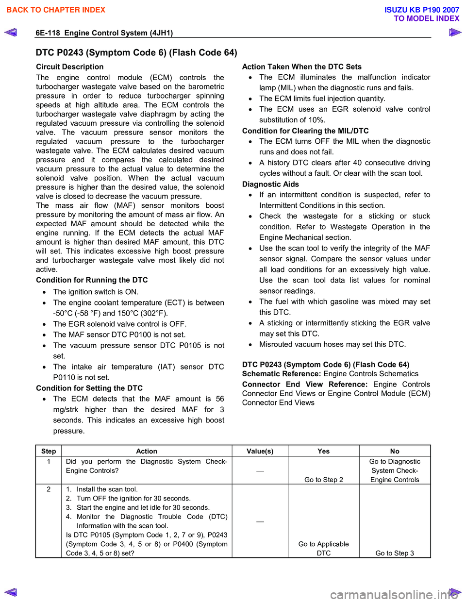
DTC P0243 (Symptom Code 6) (Flash Code 64)
Circuit Description
The engine control module (ECM) controls the
turbocharger wastegate valve based on the barometric
pressure in order to reduce turbocharger spinning
speeds at high altitude area. The ECM controls the
turbocharger wastegate valve diaphragm by acting the
regulated vacuum pressure via controlling the solenoid
valve. The vacuum pressure sensor monitors the
regulated vacuum pressure to the turbocharge
r
wastegate valve. The ECM calculates desired vacuum
pressure and it compares the calculated desired
vacuum pressure to the actual value to determine the
solenoid valve position. W hen the actual vacuum
pressure is higher than the desired value, the solenoid
valve is closed to decrease the vacuum pressure.
The mass air flow (MAF) sensor monitors boost
pressure by monitoring the amount of mass air flow. An
expected MAF amount should be detected while the
engine running. If the ECM detects the actual MAF
amount is higher than desired MAF amount, this DTC
will set. This indicates excessive high boost pressure
and turbocharger wastegate valve most likely did not
active.
Condition for Running the DTC
• The ignition switch is ON.
• The engine coolant temperature (ECT) is between
-50°C (-58 °F) and 150°C (302°F).
• The EGR solenoid valve control is OFF.
• The MAF sensor DTC P0100 is not set.
• The vacuum pressure sensor DTC P0105 is not
set.
• The intake air temperature (IAT) sensor DTC
P0110 is not set.
Condition for Setting the DTC
• The ECM detects that the MAF amount is 56
mg/strk higher than the desired MAF for 3
seconds. This indicates an excessive high boost
pressure.
Action Taken When the DTC Sets
• The ECM illuminates the malfunction indicato
r
lamp (MIL) when the diagnostic runs and fails.
• The ECM limits fuel injection quantity.
• The ECM uses an EGR solenoid valve control
substitution of 10%.
Condition for Clearing the MIL/DTC
• The ECM turns OFF the MIL when the diagnostic
runs and does not fail.
• A history DTC clears after 40 consecutive driving
cycles without a fault. Or clear with the scan tool.
Diagnostic Aids
• If an intermittent condition is suspected, refer to
Intermittent Conditions in this section.
• Check the wastegate for a sticking or stuck
condition. Refer to W astegate Operation in the
Engine Mechanical section.
• Use the scan tool to verify the integrity of the MAF
sensor signal. Compare the sensor values unde
r
all load conditions for an excessively high value.
Use the scan tool data list values for nominal
sensor readings.
• The fuel with which gasoline was mixed may set
this DTC.
• A sticking or intermittently sticking the EGR valve
may set this DTC.
• Misrouted vacuum hoses may set this DTC.
DTC P0243 (Symptom Code 6) (Flash Code 64)
Schematic Reference: Engine Controls Schematics
Connector End View Reference: Engine Controls
Connector End Views or Engine Control Module (ECM)
Connector End Views
Step Action Value(s) Yes No
1 Did you perform the Diagnostic System Check-
Engine Controls?
Go to Step 2 Go to Diagnostic
System Check-
Engine Controls
2 1. Install the scan tool. 2. Turn OFF the ignition for 30 seconds.
3. Start the engine and let idle for 30 seconds.
4. Monitor the Diagnostic Trouble Code (DTC) Information with the scan tool.
Is DTC P0105 (Symptom Code 1, 2, 7 or 9), P0243
(Symptom Code 3, 4, 5 or 8) or P0400 (Symptom
Code 3, 4, 5 or 8) set?
Go to Applicable DTC Go to Step 3
BACK TO CHAPTER INDEX
TO MODEL INDEX
ISUZU KB P190 2007
Page 1153 of 6020
Engine Control System (4JH1) 6E-119
Step Action Value(s) Yes No
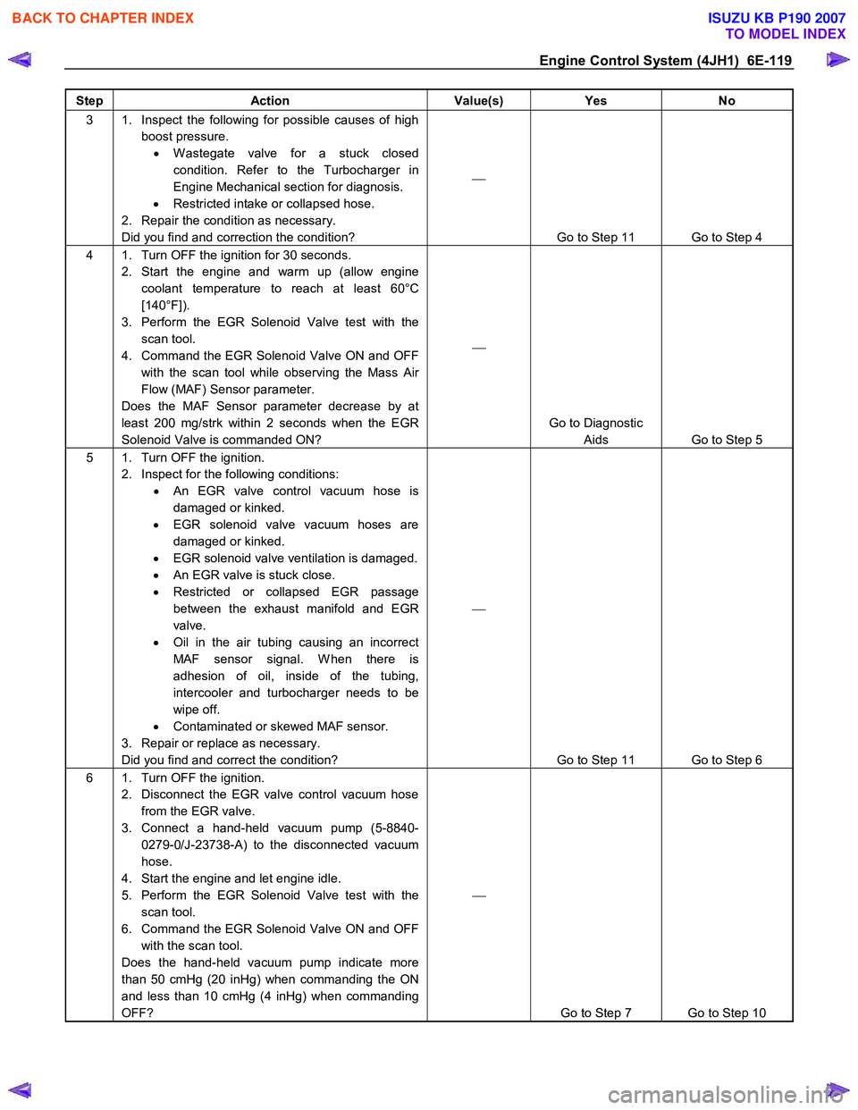
3 1. Inspect the following for possible causes of high
boost pressure. • W astegate valve for a stuck closed
condition. Refer to the Turbocharger in
Engine Mechanical section for diagnosis.
• Restricted intake or collapsed hose.
2. Repair the condition as necessary.
Did you find and correction the condition?
Go to Step 11 Go to Step 4
4 1. Turn OFF the ignition for 30 seconds. 2. Start the engine and warm up (allow engine coolant temperature to reach at least 60°C
[140°F]).
3. Perform the EGR Solenoid Valve test with the scan tool.
4. Command the EGR Solenoid Valve ON and OFF with the scan tool while observing the Mass Air
Flow (MAF) Sensor parameter.
Does the MAF Sensor parameter decrease by at
least 200 mg/strk within 2 seconds when the EGR
Solenoid Valve is commanded ON?
Go to Diagnostic Aids Go to Step 5
5 1. Turn OFF the ignition. 2. Inspect for the following conditions: • An EGR valve control vacuum hose is
damaged or kinked.
• EGR solenoid valve vacuum hoses are
damaged or kinked.
• EGR solenoid valve ventilation is damaged.
• An EGR valve is stuck close.
• Restricted or collapsed EGR passage
between the exhaust manifold and EGR
valve.
• Oil in the air tubing causing an incorrect
MAF sensor signal. W hen there is
adhesion of oil, inside of the tubing,
intercooler and turbocharger needs to be
wipe off.
• Contaminated or skewed MAF sensor.
3. Repair or replace as necessary.
Did you find and correct the condition?
Go to Step 11 Go to Step 6
6 1. Turn OFF the ignition. 2. Disconnect the EGR valve control vacuum hose from the EGR valve.
3. Connect a hand-held vacuum pump (5-8840- 0279-0/J-23738-A) to the disconnected vacuum
hose.
4. Start the engine and let engine idle.
5. Perform the EGR Solenoid Valve test with the scan tool.
6. Command the EGR Solenoid Valve ON and OFF with the scan tool.
Does the hand-held vacuum pump indicate more
than 50 cmHg (20 inHg) when commanding the ON
and less than 10 cmHg (4 inHg) when commanding
OFF?
Go to Step 7 Go to Step 10
BACK TO CHAPTER INDEX
TO MODEL INDEX
ISUZU KB P190 2007
Page 1154 of 6020
6E-120 Engine Control System (4JH1)
Step Action Value(s) Yes No
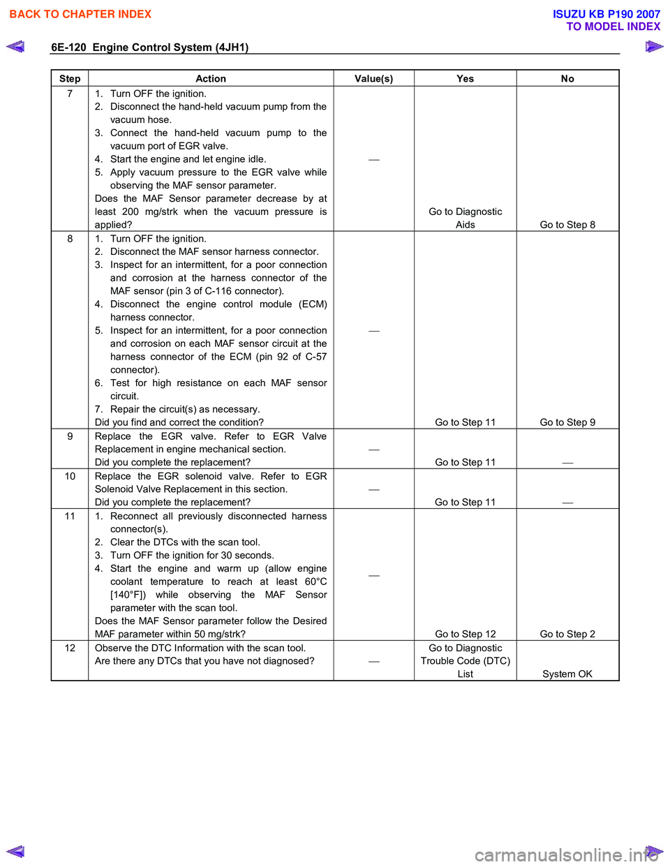
7 1. Turn OFF the ignition.
2. Disconnect the hand-held vacuum pump from the vacuum hose.
3. Connect the hand-held vacuum pump to the vacuum port of EGR valve.
4. Start the engine and let engine idle.
5. Apply vacuum pressure to the EGR valve while observing the MAF sensor parameter.
Does the MAF Sensor parameter decrease by at
least 200 mg/strk when the vacuum pressure is
applied?
Go to Diagnostic Aids Go to Step 8
8 1. Turn OFF the ignition. 2. Disconnect the MAF sensor harness connector.
3. Inspect for an intermittent, for a poor connection and corrosion at the harness connector of the
MAF sensor (pin 3 of C-116 connector).
4. Disconnect the engine control module (ECM) harness connector.
5. Inspect for an intermittent, for a poor connection and corrosion on each MAF sensor circuit at the
harness connector of the ECM (pin 92 of C-57
connector).
6. Test for high resistance on each MAF sensor circuit.
7. Repair the circuit(s) as necessary.
Did you find and correct the condition?
Go to Step 11 Go to Step 9
9 Replace the EGR valve. Refer to EGR Valve Replacement in engine mechanical section.
Did you complete the replacement?
Go to Step 11
10 Replace the EGR solenoid valve. Refer to EGR
Solenoid Valve Replacement in this section.
Did you complete the replacement?
Go to Step 11
11 1. Reconnect all previously disconnected harness
connector(s).
2. Clear the DTCs with the scan tool.
3. Turn OFF the ignition for 30 seconds.
4. Start the engine and warm up (allow engine coolant temperature to reach at least 60°C
[140°F]) while observing the MAF Sensor
parameter with the scan tool.
Does the MAF Sensor parameter follow the Desired
MAF parameter within 50 mg/strk?
Go to Step 12 Go to Step 2
12 Observe the DTC Information with the scan tool. Are there any DTCs that you have not diagnosed? Go to Diagnostic
Trouble Code (DTC) List System OK
BACK TO CHAPTER INDEX
TO MODEL INDEX
ISUZU KB P190 2007
Page 1170 of 6020
6E-136 Engine Control System (4JH1)
DTC P0380 (Symptom Code 4) (Flash Code 66)
Circuit Description
The engine control module (ECM) controls the glo
w
relay which supplies power to the glow plugs based on
engine coolant temperature. In the after glow phase, the
glow indicator light is not illuminated but glow plugs
remain active for a certain period. If the ECM detects an
open circuit or short to ground on the glow relay control
circuit, this DTC will set.
Condition for Running the DTC
• The ignition switch is ON.
Condition for Setting the DTC
• The ECM detects that the low voltage condition on
the glow relay control circuit for longer than 3
seconds when the relay is commanded OFF.
Action Taken When the DTC Sets
• The ECM illuminates the malfunction indicato
r
lamp (MIL) when the diagnostic runs and fails.
Condition for Clearing the MIL/DTC
• The ECM turns OFF the MIL when the diagnostic
runs and does not fail.
• A history DTC clears after 40 consecutive driving
cycles without a fault. Or clear with the scan tool.
Notice:
• The glow relay is commanded OFF with ignition
ON and engine OFF when the engine coolant
temperature is reached at 30°C (86°F).
• The glow relay is commanded OFF with engine
run when the engine coolant temperature is
reached at 60°C (140°F).
DTC P0380 (Symptom Code 4) (Flash Code 66)
Schematic Reference: Engine Controls Schematics
Connector End View Reference: Engine Controls
Connector End Views or Engine Control Module (ECM)
Connector End Views
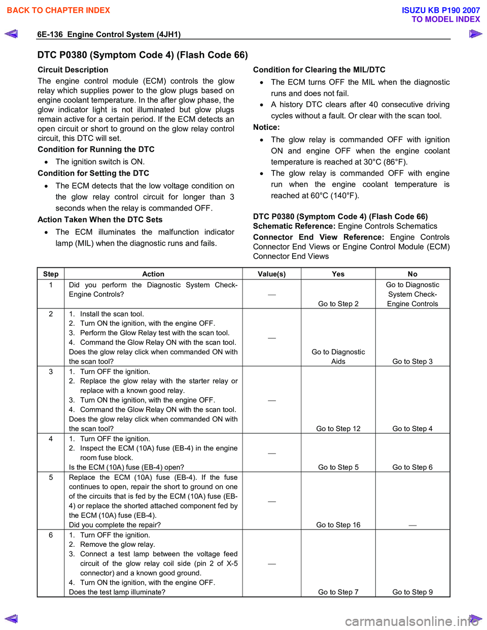
Step Action Value(s) Yes No
1 Did you perform the Diagnostic System Check-
Engine Controls?
Go to Step 2 Go to Diagnostic
System Check-
Engine Controls
2 1. Install the scan tool. 2. Turn ON the ignition, with the engine OFF.
3. Perform the Glow Relay test with the scan tool.
4. Command the Glow Relay ON with the scan tool.
Does the glow relay click when commanded ON with
the scan tool?
Go to Diagnostic Aids Go to Step 3
3 1. Turn OFF the ignition. 2. Replace the glow relay with the starter relay or replace with a known good relay.
3. Turn ON the ignition, with the engine OFF.
4. Command the Glow Relay ON with the scan tool.
Does the glow relay click when commanded ON with
the scan tool?
Go to Step 12 Go to Step 4
4 1. Turn OFF the ignition. 2. Inspect the ECM (10A) fuse (EB-4) in the engine room fuse block.
Is the ECM (10A) fuse (EB-4) open?
Go to Step 5 Go to Step 6
5 Replace the ECM (10A) fuse (EB-4). If the fuse continues to open, repair the short to ground on one
of the circuits that is fed by the ECM (10A) fuse (EB-
4) or replace the shorted attached component fed by
the ECM (10A) fuse (EB-4).
Did you complete the repair?
Go to Step 16
6 1. Turn OFF the ignition.
2. Remove the glow relay.
3. Connect a test lamp between the voltage feed circuit of the glow relay coil side (pin 2 of X-5
connector) and a known good ground.
4. Turn ON the ignition, with the engine OFF.
Does the test lamp illuminate?
Go to Step 7 Go to Step 9
BACK TO CHAPTER INDEX
TO MODEL INDEX
ISUZU KB P190 2007
Page 1171 of 6020
Engine Control System (4JH1) 6E-137
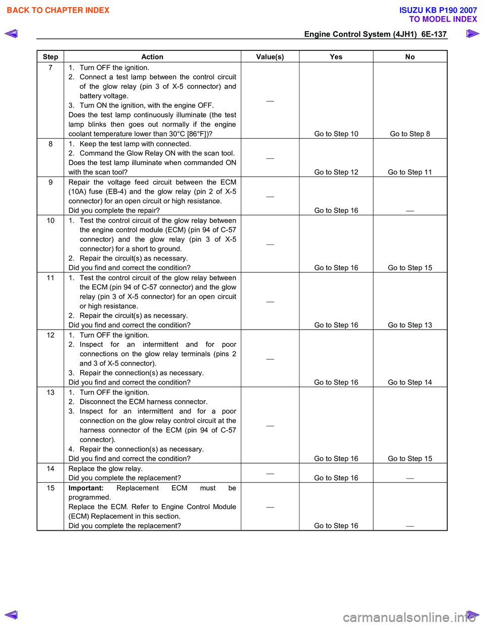
Step Action Value(s) Yes No
7 1. Turn OFF the ignition.
2. Connect a test lamp between the control circuit of the glow relay (pin 3 of X-5 connector) and
battery voltage.
3. Turn ON the ignition, with the engine OFF.
Does the test lamp continuously illuminate (the test
lamp blinks then goes out normally if the engine
coolant temperature lower than 30°C [86°F])?
Go to Step 10 Go to Step 8
8 1. Keep the test lamp with connected. 2. Command the Glow Relay ON with the scan tool.
Does the test lamp illuminate when commanded ON
with the scan tool?
Go to Step 12 Go to Step 11
9 Repair the voltage feed circuit between the ECM (10A) fuse (EB-4) and the glow relay (pin 2 of X-5
connector) for an open circuit or high resistance.
Did you complete the repair?
Go to Step 16
10 1. Test the control circuit of the glow relay between
the engine control module (ECM) (pin 94 of C-57
connector) and the glow relay (pin 3 of X-5
connector) for a short to ground.
2. Repair the circuit(s) as necessary.
Did you find and correct the condition?
Go to Step 16 Go to Step 15
11 1. Test the control circuit of the glow relay between the ECM (pin 94 of C-57 connector) and the glow
relay (pin 3 of X-5 connector) for an open circuit
or high resistance.
2. Repair the circuit(s) as necessary.
Did you find and correct the condition?
Go to Step 16 Go to Step 13
12 1. Turn OFF the ignition. 2. Inspect for an intermittent and for poor connections on the glow relay terminals (pins 2
and 3 of X-5 connector).
3. Repair the connection(s) as necessary.
Did you find and correct the condition?
Go to Step 16 Go to Step 14
13 1. Turn OFF the ignition. 2. Disconnect the ECM harness connector.
3. Inspect for an intermittent and for a poor connection on the glow relay control circuit at the
harness connector of the ECM (pin 94 of C-57
connector).
4. Repair the connection(s) as necessary.
Did you find and correct the condition?
Go to Step 16 Go to Step 15
14 Replace the glow relay. Did you complete the replacement?
Go to Step 16
15 Important: Replacement ECM must be
programmed.
Replace the ECM. Refer to Engine Control Module
(ECM) Replacement in this section.
Did you complete the replacement?
Go to Step 16
BACK TO CHAPTER INDEX
TO MODEL INDEX
ISUZU KB P190 2007