2007 ISUZU KB P190 coolant temperature
[x] Cancel search: coolant temperaturePage 952 of 6020

6B – 8 ENGINE COOLING
Draining and Refilling Cooling System
Before draining the cooling system, inspect the system and
perform any necessary service to ensure that it is clean, does
not leak and is in proper working order. The engine coolant
(EC) level should be between the “MIN" and “MAX" lines o
f
reserve tank when the engine is cold. If low, check for leakage
and add EC up to the “MAX" line.
There should not be any excessive deposit of rust or scales
around the radiator cap or radiator filler hole, and the EC
should also be free from oil.
Replace the EC if excessively dirty.
P1010064
1. Completely drain the cooling system by opening the drain
plug at the bottom of the radiator.
2. Remove the radiator cap.
WARNING: To avoid the danger of being burned, do not
remove the cap while the engine and radiator are still hot.
Scalding fluid and steam can be blown out unde
r
pressure.
3. Disconnect all hoses from the EC reserve tank.
Scrub and clean the inside of the reserve tank with soap and water. Flush it well with clean water, then drain it.
Install the reserve tank and hoses.
4. Refill the cooling system with the EC using a solution that is at least 50 percent antifreeze.
Procedure for filling with coolant (in case of full change)
• Make sure that the engine is cool.
• Open radiator cap pour coolant up to filler neck.
• Pour coolant into reservoir tank up to “MAX" line.
• Tighten radiator cap and start the engine. After idling for 2
to 3 minutes, stop the engine and reopen radiator cap. If the
water level is lower, replenish.
WARNING: When the coolant is heated to a high
temperature, be sure not to loosen or remove the radiato
r
cap. Otherwise you might get scalded by not vapor or
boiling water. To open the radiator cap, put a piece of
thick cloth on the cap and loosen the cap slowly to reduce
the pressure when the coolant has become cooler.
BACK TO CHAPTER INDEX
TO MODEL INDEX
ISUZU KB P190 2007
Page 953 of 6020

ENGINE COOLING 6B – 9
• After tightening radiator cap, warm up the engine at about
2000 rpm. Set heater adjustment to the highest temperature
position, and let the coolant circulate also into heater wate
r
system.
• Check to see the thermostat has opened through the
needle position of water thermometer, conduct a 5–minute
idling again and stop the engine.
• W hen the engine has been cooled, check filler neck fo
r
water level and replenish if required. Should extreme
shortage of coolant is found, check the cooling system and
reservoir tank hose for leakage.
• Pour coolant into the reservoir tank up to “MAX" line.
BACK TO CHAPTER INDEX
TO MODEL INDEX
ISUZU KB P190 2007
Page 957 of 6020

ENGINE COOLING 6B – 13
THERMOSTAT
REMOVAL AND INSTALLATION
Read this Section carefully before performing any removal and installation procedure. This Section gives you
important points as well as the order of operation. Be sure that you understand everything in this Section before you
begin.
Removal
1. Radiator Upper Hose 1) Partially drain the engine coolant.
2) Remove the radiator upper hose.
2. Water Outlet Pipe 3) Disconnect the turbocharger-cooling pipe from outlet pipe.
4) Loosen the fixing bolt and remove the water outlet bolt.
3. Thermostat
Remove the thermostat from the thermostat housing.
Take care not to damage the thermostat.
031R300003
Inspection and Repair
Make the necessary adjustments, repairs, and part
replacements if excessive wear or damage is discovered
during inspection.
031RY00005
Operating Test of Thermostat
1. Completely submerge the thermostat in water.
2. Heat the water. Stir the water constantly to avoid direct heat being
applied to the thermostat.
3. Check the thermostat initial opening temperature.
Thermostat Initial Opening Temperature °C ( °F)
82 (180)
4. Check the thermostat full opening temperature.
Thermostat Full Opening Temperature °C ( °F)
95 (203)
Valve Lift At Fully Open Position mm (in)
9.5 (0.37)
BACK TO CHAPTER INDEX
TO MODEL INDEX
ISUZU KB P190 2007
Page 1037 of 6020
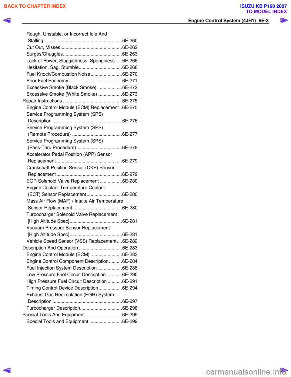
Engine Control System (4JH1) 6E-3
Rough, Unstable, or In co rr ect Idle And
Stallin g........................................................... .6E -260
Cut Out, Mi sses.............................................. .6E -262
Su rge s/Chuggle s............................................ .6E -263
La ck of Po wer, Sluggi shne ss, Spongine ss .... .6E -266
He sitation, Sag, Stu mble................................ .6E -268
Fuel Kno ck /Co mbu stion Noi se ....................... .6E -270
Poor F uel E cono my........................................ .6E -271
E xc ess ive S moke (B la ck S m oke) ................. .6E -272
E xc ess ive S moke (W hite S moke) ................. .6E -273
Repair In str u ctions ............................................ .6E -275
Engine Control Module (ECM) Replacement ..6E-275
Service Programming System (SPS)
Description .....................................................6E-276
Service Programming System (SPS)
(Remote Procedure) ......................................6E-277
Service Programming System (SPS)
(Pass-Thru Procedure) ..................................6E-278
Accelerator Pedal Position (APP) Sensor
Replacement ..................................................6E-279
Crankshaft Position Sensor (CKP) Sensor
Replacement ..................................................6E-279
EGR Solenoid Valve Replacement .................6E-280
Engine Coolant Temperature Coolant
(ECT) Sensor Replacement ...........................6E-280
Mass Air Flow (MAF) / Intake Air Temperature
Sensor Replacement......................................6E-280
Turbocharger Solenoid Valve Replacement
[High Altitude Spec] ........................................6E-281
Vacuum Pressure Sensor Replacement
[High Altitude Spec] ........................................6E-281
Vehicle Speed Sensor (VSS) Replacement ....6E-282
Description And Operation .................................6E-283 Engine Control Module (ECM) .......................6E-283
Engine Control Component Description ..........6E-284
Fuel Injection System Description ...................6E-288
Low Pressure Fuel Circuit Description ............6E-290
High Pressure Fuel Circuit Description ...........6E-291
Timing Control Device Description ..................6E-294
Exhaust Gas Recirculation (EGR) System
Description .....................................................6E-297
Turbocharger Description................................6E-298
Special Tools And Equipment ............................6E-299 Special Tools and Equipment .........................6E-299
BACK TO CHAPTER INDEX
TO MODEL INDEX
ISUZU KB P190 2007
Page 1038 of 6020
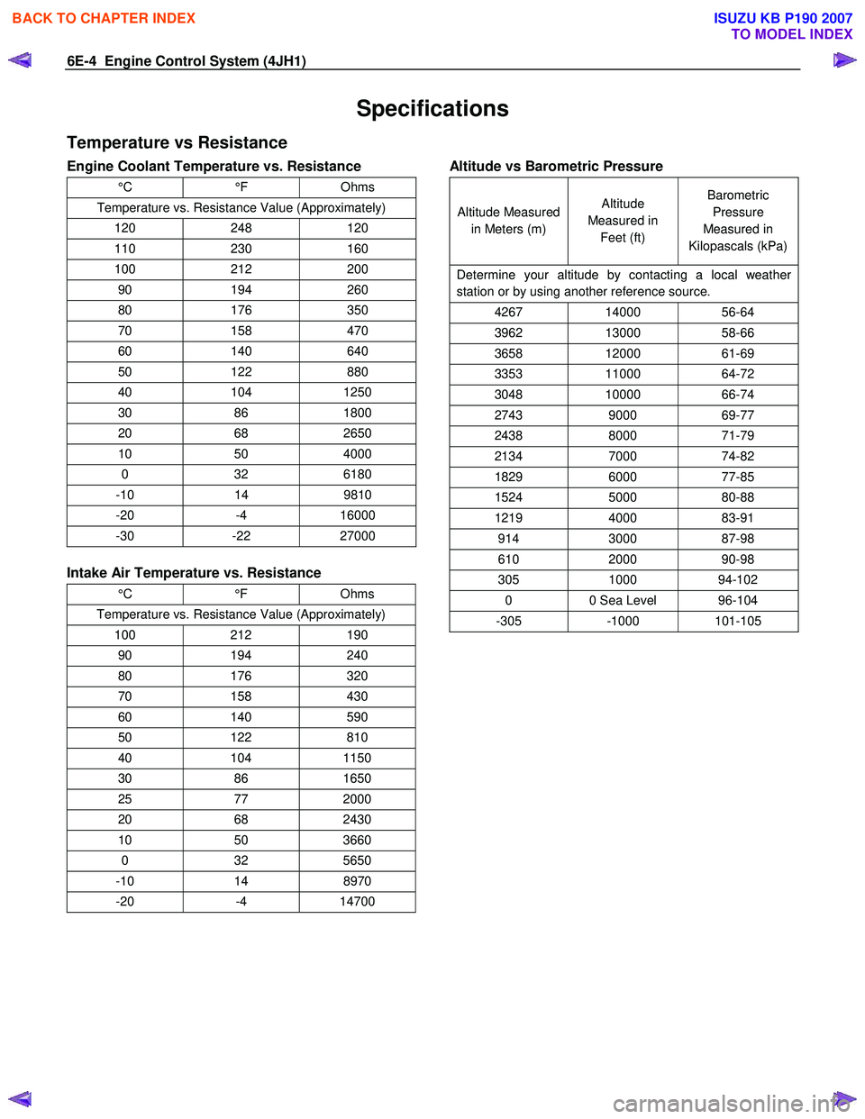
6E-4 Engine Control System (4JH1)
Specifications
Temperature vs Resistance
Engine Coolant Temperature vs. Resistance
°C °F Ohms
Temperature vs. Resistance Value (Approximately)
120 248 120
110 230 160
100 212 200
90 194 260
80 176 350
70 158 470
60 140 640
50 122 880
40 104 1250
30 86 1800
20 68 2650
10 50 4000
0 32 6180
-10 14 9810
-20 -4 16000
-30 -22 27000
Intake Air Temperature vs. Resistance
°C °F Ohms
Temperature vs. Resistance Value (Approximately)
100 212 190
90 194 240
80 176 320
70 158 430
60 140 590
50 122 810
40 104 1150
30 86 1650
25 77 2000
20 68 2430
10 50 3660
0 32 5650
-10 14 8970
-20 -4 14700
Altitude vs Barometric Pressure
Altitude Measured
in Meters (m) Altitude
Measured in Feet (ft) Barometric
Pressure
Measured in
Kilopascals (kPa)
Determine your altitude by contacting a local weather
station or by using another reference source.
4267 14000 56-64
3962 13000 58-66
3658 12000 61-69
3353 11000 64-72
3048 10000 66-74
2743 9000 69-77
2438 8000 71-79
2134 7000 74-82
1829 6000 77-85
1524 5000 80-88
1219 4000 83-91
914 3000 87-98
610 2000 90-98
305 1000 94-102
0 0 Sea Level 96-104
-305 -1000 101-105
BACK TO CHAPTER INDEX
TO MODEL INDEX
ISUZU KB P190 2007
Page 1054 of 6020
6E-20 Engine Control System (4JH1)
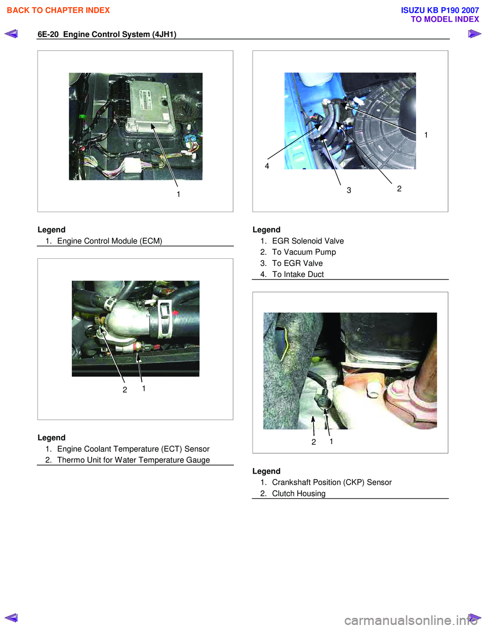
1
Legend
1. Engine Control Module (ECM)
2 1
Legend
1. Engine Coolant Temperature (ECT) Sensor
2. Thermo Unit for W ater Temperature Gauge
2
3 14
Legend
1. EGR Solenoid Valve
2. To Vacuum Pump
3. To EGR Valve
4. To Intake Duct
2 1
Legend
1. Crankshaft Position (CKP) Sensor
2. Clutch Housing
BACK TO CHAPTER INDEX
TO MODEL INDEX
ISUZU KB P190 2007
Page 1061 of 6020
Engine Control System (4JH1) 6E-27
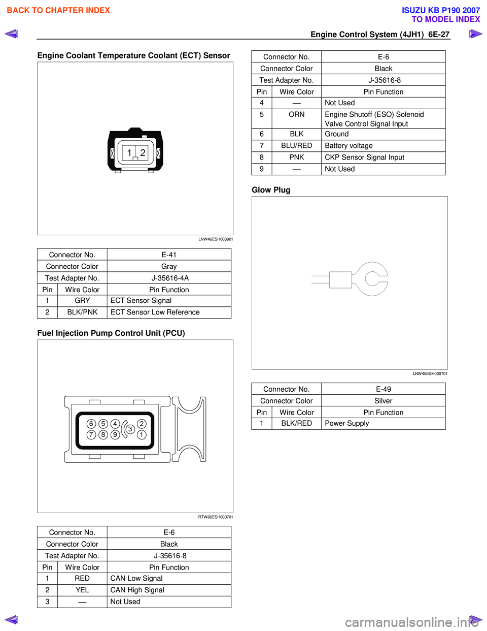
Engine Coolant Temperature Coolant (ECT) Sensor
LNW 46ESH003901
Connector No. E-41
Connector Color Gray
Test Adapter No. J-35616-4A
Pin W ire Color Pin Function
1 GRY ECT Sensor Signal
2 BLK/PNK ECT Sensor Low Reference
Fuel Injection Pump Control Unit (PCU)
RTW 66ESH000701
Connector No. E-6
Connector Color Black
Test Adapter No. J-35616-8
Pin W ire Color Pin Function
1 RED CAN Low Signal
2 YEL CAN High Signal
3
Not Used
Connector No. E-6
Connector Color Black
Test Adapter No. J-35616-8
Pin W ire Color Pin Function
4
Not Used
5 ORN Engine Shutoff (ESO) Solenoid
Valve Control Signal Input
6 BLK Ground
7 BLU/RED Battery voltage
8 PNK CKP Sensor Signal Input
9
Not Used
Glow Plug
LNW 46ESH000701
Connector No. E-49
Connector Color Silver
Pin W ire Color Pin Function
1 BLK/RED Power Supply
BACK TO CHAPTER INDEX
TO MODEL INDEX
ISUZU KB P190 2007
Page 1070 of 6020
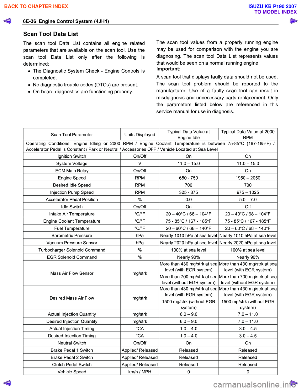
6E-36 Engine Control System (4JH1)
Scan Tool Data List
The scan tool Data List contains all engine related
parameters that are available on the scan tool. Use the
scan tool Data List only after the following is
determined: • The Diagnostic System Check - Engine Controls is
completed.
• No diagnostic trouble codes (DTCs) are present.
• On-board diagnostics are functioning properly.
The scan tool values from a properly running engine
may be used for comparison with the engine you are
diagnosing. The scan tool Data List represents values
that would be seen on a normal running engine.
Important:
A scan tool that displays faulty data should not be used.
The scan tool problem should be reported to the
manufacturer. Use of a faulty scan tool can result in
misdiagnosis and unnecessary parts replacement. Onl
y
the parameters listed below are referenced in this
service manual for use in diagnosis.
Scan Tool Parameter Units DisplayedTypical Data Value at
Engine Idle
Typical Data Value at 2000
RPM
Operating Conditions: Engine Idling or 2000 RPM / Engine Coolant Temperature is between 75-85 °C (167-185 °F) /
Accelerator Pedal is Constant / Park or Neutral / Accessories OFF / Vehicle Located at Sea Level
Ignition Switch On/Off On On
System Voltage V 11.0 – 15.0 11.0 – 15.0
ECM Main Relay On/Off On On
Engine Speed RPM 650 - 750 1950 – 2050
Desired Idle Speed RPM 700 700
Injection Pump Speed RPM 325 - 375 975 – 1025
Accelerator Pedal Position % 0.0 5.0 – 7.0
Idle Switch On/Off On Off
Intake Air Temperature °C/°F 20 – 40°C / 68 – 104°F 20 – 40°C / 68 – 104°F
Engine Coolant Temperature °C/°F 75 - 85 °C / 167 - 185 °F 75 - 85 °C / 167 - 185 °F
Fuel Temperature °C/°F 20 – 60°C / 68 – 140°F 20 – 60°C / 68 – 140°F
Barometric Pressure hPa Nearly 1010 hPa at sea level Nearly 1010 hPa at sea level
Vacuum Pressure Sensor hPa Nearly 2020 hPa at sea level Nearly 2020 hPa at sea level
Turbocharger Solenoid Command % 100% at sea level 100% at sea level
EGR Solenoid Command % Nearly 90% Nearly 90%
Mass Air Flow Sensor mg/strk
More than 430 mg/strk at sea
level (with EGR system)
More than 700 mg/strk at sea
level (without EGR system)
More than 430 mg/strk at sea
level (with EGR system)
More than 700 mg/strk at sea
level (without EGR system)
Desired Mass Air Flow mg/strk
More than 430 mg/strk at sea
level (with EGR system)
1500 mg/strk (without EGR
system)
More than 430 mg/strk at sea
level (with EGR system)
1500 mg/strk (without EGR
system)
Actual Injection Quantity mg/strk 6.0 – 9.0 7.0 – 11.0
Desired Injection Quantity mg/strk 6.0 – 9.0 7.0 – 11.0
Actual Injection Timing °CA 1.0 – 4.0 3.0 – 4.5
Desired Injection Timing °CA 1.0 – 4.0 3.0 – 4.5
Neutral Switch On/Off On On
Brake Pedal 1 Switch Applied/ ReleasedReleased Released
Brake Pedal 2 Switch Applied/ ReleasedReleased Released
Clutch Pedal Switch Applied/ ReleasedReleased Released
Vehicle Speed km/h / MPH 0 0
BACK TO CHAPTER INDEX
TO MODEL INDEX
ISUZU KB P190 2007