Page 5169 of 6020

ELECTRICAL-BODY AND CHASSIS 8A-231
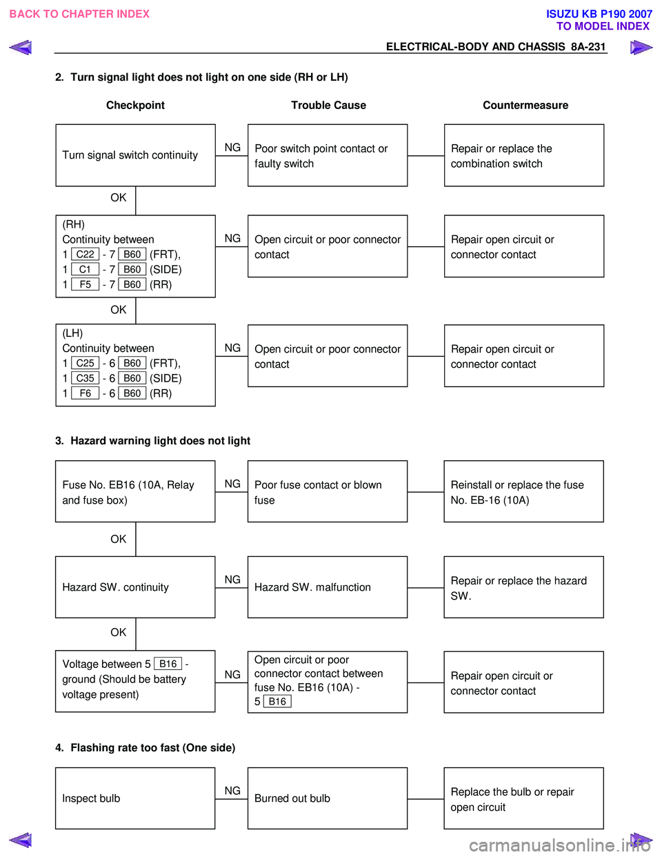
2. Turn signal light does not light on one side (RH or LH)
Checkpoint Trouble Cause Countermeasure
Repair open circuit or
connector contact
Open circuit or poor connector
contact
NG
(LH)
Continuity between
1
C25 - 6 B60 (FRT),
1
C35 - 6 B60 (SIDE)
1
F6 - 6 B60 (RR)
(RH)
Continuity between
1
C22 - 7 B60 (FRT),
1
C1 - 7 B60 (SIDE)
1
F5 - 7 B60 (RR)
Repair or replace the
combination switch
Turn signal switch continuity
Poor switch point contact or
faulty switch
NG
OK
OK
Repair open circuit or
connector contact
Open circuit or poor connector
contact
NG
3. Hazard warning light does not light
Repair or replace the hazard
SW .
Hazard SW . malfunction
NG
Voltage between 5
B16 -
ground (Should be battery
voltage present)
Hazard SW . continuity
Reinstall or replace the fuse
No. EB-16 (10A)
Fuse No. EB16 (10A, Relay
and fuse box)
Poor fuse contact or blown
fuse
NG
OK
OK
Repair open circuit or
connector contact
Open circuit or poor
connector contact between
fuse No. EB16 (10A) -
5
B16
NG
4. Flashing rate too fast (One side)
Replace the bulb or repair
open circuitInspect bulbBurned out bulb
NG
BACK TO CHAPTER INDEX TO MODEL INDEXISUZU KB P190 2007
Page 5171 of 6020
ELECTRICAL-BODY AND CHASSIS 8A-233
HORN
1. Both sides of horn do not sound
Checkpoint Trouble Cause Countermeasure
Repair the grounding point
Poor ground contact
NG
Horn relay
Grounding point
Reinstall or replace fuse No.
EB15 (10A)
Fuse No EB15 (10A, Relay
and fuse box)
Poor fuse contact or blown
fuse
NG
OK
OK
Reinstall or replace the horn
relay
Poor relay contact or faulty
horn relay
NG
Voltage between connector
3
X3 - ground or 1 X3
- ground (Should be battery
v oltage present) OK
Repair open circuit or
reconnect the connector
Open circuit or poor connector
contact between fuse No.
EB15 (10A) and horn relay
NG
Remov e steering pad and
steering wheel
OK
Horn switch continuity
OK
Repair or replace the horn
switch
Poor switch point contact or
faulty switch
NG
Continuity between
5
X3 - 10 B60
2
X3 - 1 C20 (1 C21 )
OK
Repair open circuit or
connector contact
Open circuit or poor connector
contact
NG
BACK TO CHAPTER INDEX
TO MODEL INDEXISUZU KB P190 2007
Page 5204 of 6020
8A-266 ELECTRICAL-BODY AND CHASSIS
CIRCUIT DIAGRAM C24SE (RHD) WITHOUT INTERMITTENT RELAY
RTW 780XF013101
BACK TO CHAPTER INDEX
TO MODEL INDEXISUZU KB P190 2007
Page 5205 of 6020
ELECTRICAL-BODY AND CHASSIS 8A-267
CIRCUIT DIAGRAM C24SE (RHD) WITH INTERMITTENT RELAY
RTW 780XF013201
BACK TO CHAPTER INDEX
TO MODEL INDEXISUZU KB P190 2007
Page 5206 of 6020
8A-268 ELECTRICAL-BODY AND CHASSIS
CIRCUIT DIAGRAM C24SE (LHD) WITHOUT INTERMITTENT RELAY
RTW 780XF013301
BACK TO CHAPTER INDEX
TO MODEL INDEXISUZU KB P190 2007
Page 5207 of 6020
ELECTRICAL-BODY AND CHASSIS 8A-269
CIRCUIT DIAGRAM C24SE (LHD) WITH INTERMITTENT RELAY
RTW 780XF013401
BACK TO CHAPTER INDEX
TO MODEL INDEXISUZU KB P190 2007
Page 5212 of 6020

8A-274 ELECTRICAL-BODY AND CHASSIS
2. Wiper dose not operate at “ INT “ position
Checkpoint Trouble Cause Countermeasure
Replace the wiper & washer
SW .
SW . malfunction
NG
Repair grounding point contact
Grounding point
C36 (RHD),
C2 (LHD)
Poor grounding point contact
Repair open circuit or
connector contact
Voltage between the
intermittent relay harness side
connector terminal 4
C3
and the ground at the “INT”
position (Should be battery
voltage present)
Open circuit or poor connector
contact
NG
NG
OK
OK
Continuity between the wiper
& washer SW connector
terminals 4
B59 and 2 B59
at the “ INT “ position
Replace the intermittent relay
Intermittent relay function
Relay malfunction
NG
OK
3. Wiper does not operate at “LO” position
Replace the wiper motor
W iper motor function
1. Disconnect the wiper & washer SW . connector
2. Turn the starter SW . on
3. Short-circuit between the wiper & washer SW .
harness side connector terminal 3
B59 and
5
B59 .
4. Check to see if the wiper
motor rotates at a low
speed
W iper motor malfunction
NG
Replace the wiper & washer
SW .
W iper & washer SW . function
SW . malfunction
NG
OK
BACK TO CHAPTER INDEX TO MODEL INDEXISUZU KB P190 2007
Page 5214 of 6020

8A-276 ELECTRICAL-BODY AND CHASSIS
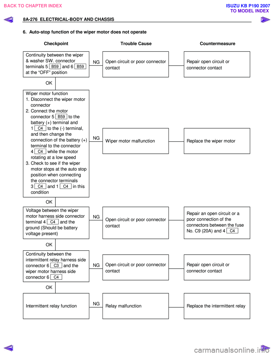
6. Auto-stop function of the wiper motor does not operate
Checkpoint Trouble Cause Countermeasure
Repair open circuit or
connector contact
Open circuit or poor connector
contact
NG
Repair open circuit or
connector contact
Open circuit or poor connector
contact
NG Continuity between the
intermittent relay harness side
connector 6
C3 and the
wiper motor harness side
connector 6
C4
Replace the intermittent relay
Relay malfunction
NG
Intermittent relay function
W iper motor function
1. Disconnect the wiper motor connector
2. Connect the motor connector 5
B59 to the
battery (+) terminal and
1
C4 to the (-) terminal,
and then change the
connection of the battery (+)
terminal to the connector
4
C4 while the motor
rotating at a low speed
3. Check to see if the wiper motor stops at the auto stop
position when connecting
the connector terminals
3
C4 and 1 C4 in this
condition
Continuity between the wiper
& washer SW . connector
terminals 5
B59 and 6 B59
at the “OFF” position
OK
Replace the wiper motor
W iper motor malfunction
NG
Repair an open circuit or a
poor connection of the
connectors between the fuse
No. C9 (20A) and 4
C4
Voltage between the wiper
motor harness side connector
terminal 4
C4 and the
ground (Should be battery
v oltage present)
Open circuit or poor connector
contact
NG
OK
OK
OK
BACK TO CHAPTER INDEX
TO MODEL INDEXISUZU KB P190 2007