2007 ISUZU KB P190 relay
[x] Cancel search: relayPage 4919 of 6020
TRANSFER CONTROL SYSTEM 7D1-45
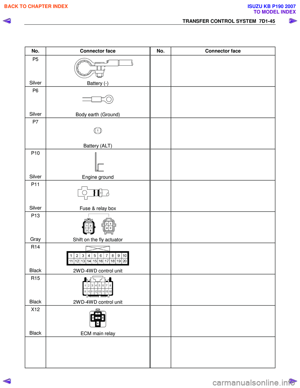
No. Connector face No. Connector face
P5
Silver
Battery (-)
P6
Silver
Body earth (Ground)
P7
Battery (ALT)
P10
Silver
Engine ground
P11
Silver
Fuse & relay box
P13
Gray
Shift on the fly actuator
R14
Black
2W D-4W D control unit
R15
Black
2W D-4W D control unit
X12
Black
ECM main relay
BACK TO CHAPTER INDEX
TO MODEL INDEX
ISUZU KB P190 2007
Page 4926 of 6020
7D1-52 TRANSFER CONTROL SYSTEM
Memory erasing procedure
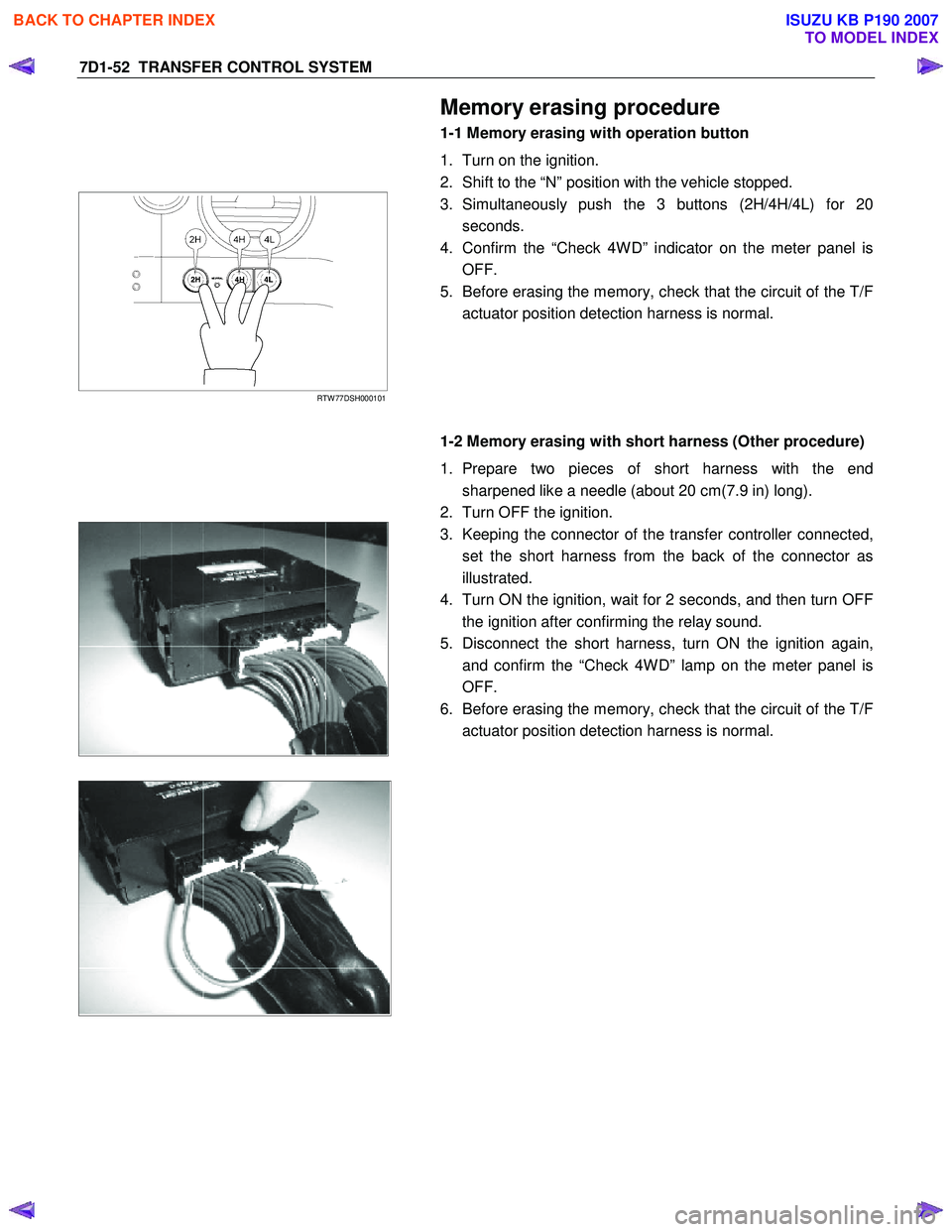
1-1 Memory erasing with operation button
1. Turn on the ignition.
2. Shift to the “N” position with the vehicle stopped.
RTW 77DSH000101
3. Simultaneously push the 3 buttons (2H/4H/4L) for 20
seconds.
4. Confirm the “Check 4W D” indicator on the meter panel is OFF.
5. Before erasing the memory, check that the circuit of the T/F actuator position detection harness is normal.
1-2 Memory erasing with short harness (Other procedure)
1. Prepare two pieces of short harness with the end sharpened like a needle (about 20 cm(7.9 in) long).
2. Turn OFF the ignition.
3. Keeping the connector of the transfer controller connected,
set the short harness from the back of the connector as
illustrated.
4. Turn ON the ignition, wait for 2 seconds, and then turn OFF the ignition after confirming the relay sound.
5. Disconnect the short harness, turn ON the ignition again, and confirm the “Check 4W D” lamp on the meter panel is
OFF.
6. Before erasing the memory, check that the circuit of the T/F actuator position detection harness is normal.
BACK TO CHAPTER INDEX
TO MODEL INDEX
ISUZU KB P190 2007
Page 4929 of 6020
TRANSFER CONTROL SYSTEM 7D1-55
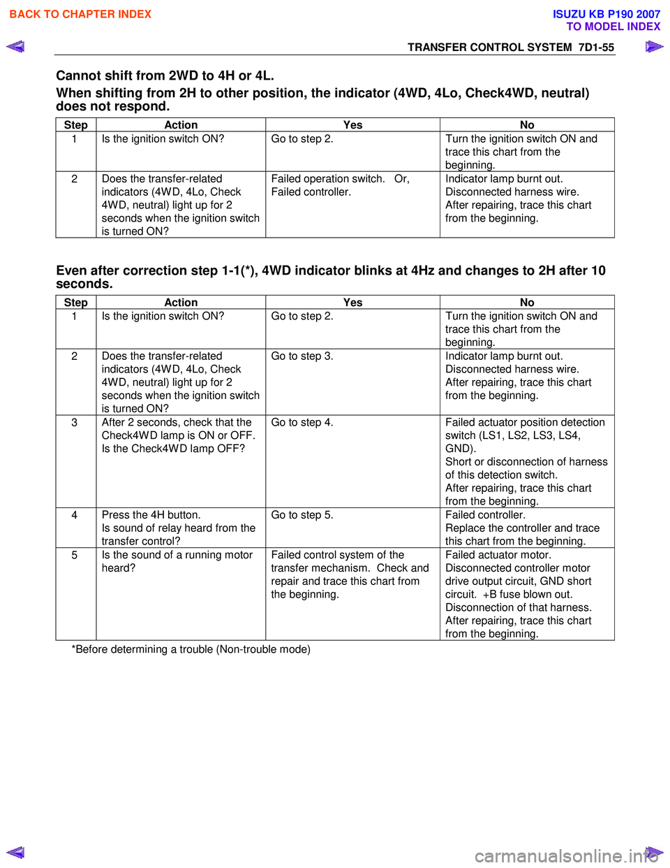
Cannot shift from 2WD to 4H or 4L.
When shifting from 2H to other position, the indicator (4WD, 4Lo, Check4WD, neutral)
does not respond.
Step Action Yes No
1 Is the ignition switch ON? Go to step 2.
Turn the ignition switch ON and
trace this chart from the
beginning.
2 Does the transfer-related
indicators (4W D, 4Lo, Check
4W D, neutral) light up for 2
seconds when the ignition switch
is turned ON? Failed operation switch. Or,
Failed controller. Indicator lamp burnt out.
Disconnected harness wire.
After repairing, trace this chart
from the beginning.
Even after correction step 1-1(*), 4WD indicator blinks at 4Hz and changes to 2H after 10
seconds.
Step Action Yes No
1 Is the ignition switch ON? Go to step 2.
Turn the ignition switch ON and
trace this chart from the
beginning.
2 Does the transfer-related
indicators (4W D, 4Lo, Check
4W D, neutral) light up for 2
seconds when the ignition switch
is turned ON? Go to step 3.
Indicator lamp burnt out.
Disconnected harness wire.
After repairing, trace this chart
from the beginning.
3 After 2 seconds, check that the
Check4W D lamp is ON or OFF.
Is the Check4W D lamp OFF? Go to step 4.
Failed actuator position detection
switch (LS1, LS2, LS3, LS4,
GND).
Short or disconnection of harness
of this detection switch.
After repairing, trace this chart
from the beginning.
4 Press the 4H button.
Is sound of relay heard from the
transfer control? Go to step 5.
Failed controller.
Replace the controller and trace
this chart from the beginning.
5 Is the sound of a running motor
heard? Failed control system of the
transfer mechanism. Check and
repair and trace this chart from
the beginning. Failed actuator motor.
Disconnected controller motor
drive output circuit, GND short
circuit. +B fuse blown out.
Disconnection of that harness.
After repairing, trace this chart
from the beginning.
*Before determining a trouble (Non-trouble mode)
BACK TO CHAPTER INDEX
TO MODEL INDEX
ISUZU KB P190 2007
Page 4931 of 6020
TRANSFER CONTROL SYSTEM 7D1-57
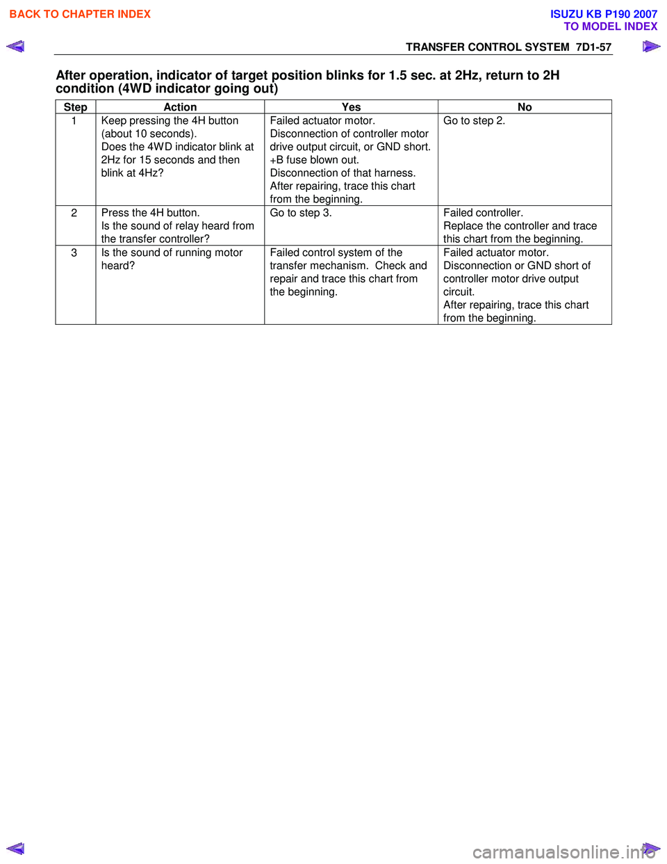
After operation, indicator of target position blinks for 1.5 sec. at 2Hz, return to 2H
condition (4WD indicator going out)
Step Action Yes No
1 Keep pressing the 4H button
(about 10 seconds).
Does the 4W D indicator blink at
2Hz for 15 seconds and then
blink at 4Hz? Failed actuator motor.
Disconnection of controller motor
drive output circuit, or GND short.
+B fuse blown out.
Disconnection of that harness.
After repairing, trace this chart
from the beginning. Go to step 2.
2
Press the 4H button.
Is the sound of relay heard from
the transfer controller? Go to step 3.
Failed controller.
Replace the controller and trace
this chart from the beginning.
3 Is the sound of running motor
heard? Failed control system of the
transfer mechanism. Check and
repair and trace this chart from
the beginning. Failed actuator motor.
Disconnection or GND short of
controller motor drive output
circuit.
After repairing, trace this chart
from the beginning.
BACK TO CHAPTER INDEX
TO MODEL INDEX
ISUZU KB P190 2007
Page 4932 of 6020
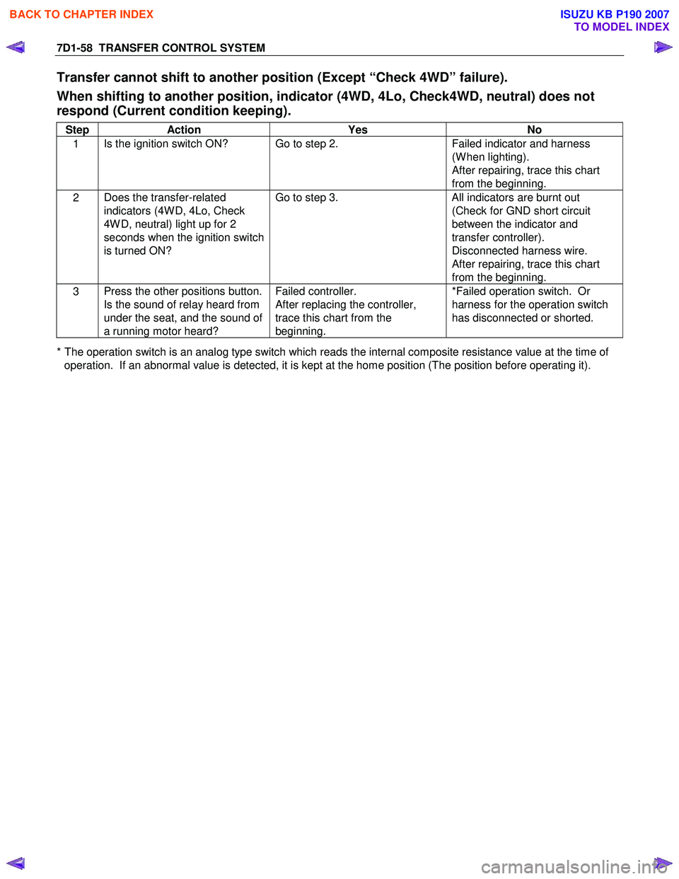
7D1-58 TRANSFER CONTROL SYSTEM
Transfer cannot shift to another position (Except “Check 4WD” failure).
When shifting to another position, indicator (4WD, 4Lo, Check4WD, neutral) does not
respond (Current condition keeping).
Step Action Yes No
1 Is the ignition switch ON? Go to step 2.
Failed indicator and harness
(W hen lighting).
After repairing, trace this chart
from the beginning.
2 Does the transfer-related
indicators (4W D, 4Lo, Check
4W D, neutral) light up for 2
seconds when the ignition switch
is turned ON? Go to step 3.
All indicators are burnt out
(Check for GND short circuit
between the indicator and
transfer controller).
Disconnected harness wire.
After repairing, trace this chart
from the beginning.
3 Press the other positions button.
Is the sound of relay heard from
under the seat, and the sound of
a running motor heard? Failed controller.
After replacing the controller,
trace this chart from the
beginning. *Failed operation switch. Or
harness for the operation switch
has disconnected or shorted.
* The operation switch is an analog type switch which reads the internal composite resistance value at the time of operation. If an abnormal value is detected, it is kept at the home position (The position before operating it).
BACK TO CHAPTER INDEX
TO MODEL INDEX
ISUZU KB P190 2007
Page 4934 of 6020
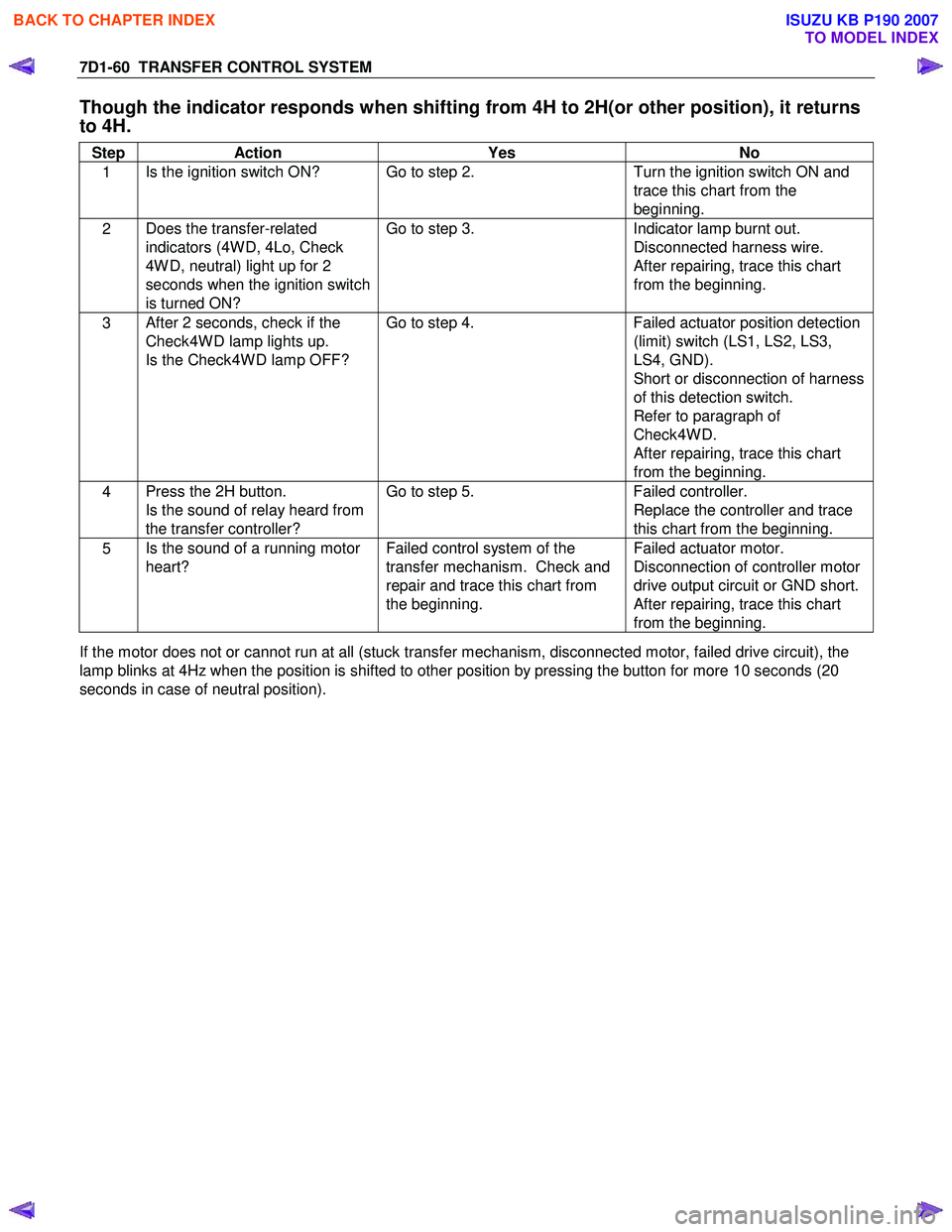
7D1-60 TRANSFER CONTROL SYSTEM
Though the indicator responds when shifting from 4H to 2H(or other position), it returns
to 4H.
Step Action Yes No
1 Is the ignition switch ON? Go to step 2.
Turn the ignition switch ON and
trace this chart from the
beginning.
2 Does the transfer-related
indicators (4W D, 4Lo, Check
4W D, neutral) light up for 2
seconds when the ignition switch
is turned ON? Go to step 3.
Indicator lamp burnt out.
Disconnected harness wire.
After repairing, trace this chart
from the beginning.
3 After 2 seconds, check if the
Check4W D lamp lights up.
Is the Check4W D lamp OFF? Go to step 4.
Failed actuator position detection
(limit) switch (LS1, LS2, LS3,
LS4, GND).
Short or disconnection of harness
of this detection switch.
Refer to paragraph of
Check4W D.
After repairing, trace this chart
from the beginning.
4 Press the 2H button.
Is the sound of relay heard from
the transfer controller? Go to step 5.
Failed controller.
Replace the controller and trace
this chart from the beginning.
5 Is the sound of a running motor
heart? Failed control system of the
transfer mechanism. Check and
repair and trace this chart from
the beginning. Failed actuator motor.
Disconnection of controller motor
drive output circuit or GND short.
After repairing, trace this chart
from the beginning.
If the motor does not or cannot run at all (stuck transfer mechanism, disconnected motor, failed drive circuit), the
lamp blinks at 4Hz when the position is shifted to other position by pressing the button for more 10 seconds (20
seconds in case of neutral position).
BACK TO CHAPTER INDEX
TO MODEL INDEX
ISUZU KB P190 2007
Page 4939 of 6020
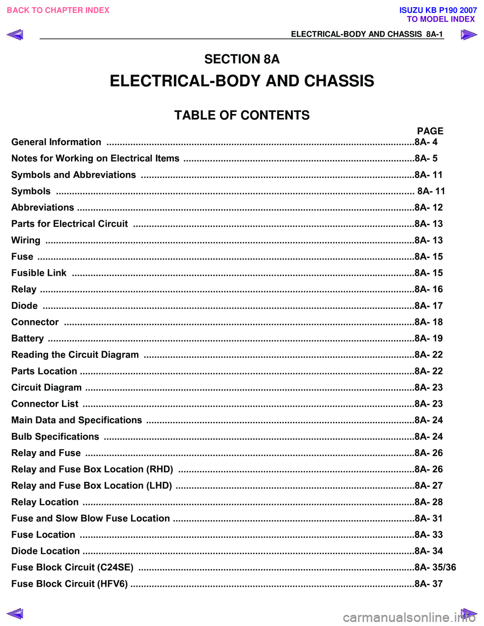
ELECTRICAL-BODY AND CHASSIS 8A-1
SECTION 8A
ELECTRICAL-BODY AND CHASSIS
TABLE OF CONTENTS
PAGE
General Information ........................................................................................................... .........8A- 4
Notes for Working on Electrical Items .......................................................................................8A - 5
Symbols and A bbreviations ..................................................................................................... ..8A- 11
Symbols ....................................................................................................................... ................ 8A- 11
Abbreviations ................................................................................................................. ..............8A- 12
Parts for Electri cal Circuit .................................................................................................. ........8A- 13
Wiring ........................................................................................................................ ...................8A- 13
Fuse .......................................................................................................................... ....................8A- 15
Fusible Link .................................................................................................................. ...............8A- 15
Relay ......................................................................................................................... ....................8A- 16
Diode ......................................................................................................................... ...................8A- 17
Connector ..................................................................................................................... ...............8A- 18
Battery ....................................................................................................................... ...................8A- 19
Reading the Circuit Diagram ................................................................................................... ...8A- 22
Parts Location ................................................................................................................ ..............8A- 22
Circuit Diagram ............................................................................................................... .............8A- 23
Connector List ................................................................................................................ .............8A- 23
Main Data and Specifications .................................................................................................. ...8A- 24
Bulb Specifications ........................................................................................................... ..........8A- 24
Relay and Fuse ................................................................................................................ ............8A- 26
Relay and Fuse Box Location (RHD) .........................................................................................8A- 26
Relay and Fuse Box Location (LHD) ..........................................................................................8A- 27
Relay Location ................................................................................................................ .............8A- 28
Fuse and Slow Blow Fuse Location ...........................................................................................8A- 31
Fuse Location ................................................................................................................. .............8A- 33
Diode Location ................................................................................................................ .............8A- 34
Fuse Block Circuit (C24SE) .................................................................................................... ....8A- 35/36
Fuse Block Circuit (HFV6) ...................................................................................................... .....8A- 37
BACK TO CHAPTER INDEX
TO MODEL INDEX
ISUZU KB P190 2007
Page 4942 of 6020
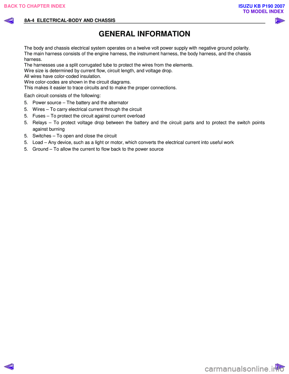
8A-4 ELECTRICAL-BODY AND CHASSIS
GENERAL INFORMATION
The body and chassis electrical system operates on a twelve volt power supply with negative ground polarity.
The main harness consists of the engine harness, the instrument harness, the body harness, and the chassis
harness.
The harnesses use a split corrugated tube to protect the wires from the elements.
W ire size is determined by current flow, circuit length, and voltage drop.
All wires have color-coded insulation.
W ire color-codes are shown in the circuit diagrams.
This makes it easier to trace circuits and to make the proper connections.
Each circuit consists of the following:
5. Power source – The battery and the alternator
5. W ires – To carry electrical current through the circuit
5. Fuses – To protect the circuit against current overload
5. Relays – To protect voltage drop between the battery and the circuit parts and to protect the switch points against burning
5. Switches – To open and close the circuit
5. Load – Any device, such as a light or motor, which converts the electrical current into useful work
5. Ground – To allow the current to flow back to the power source
BACK TO CHAPTER INDEX TO MODEL INDEXISUZU KB P190 2007