2007 ISUZU KB P190 key
[x] Cancel search: keyPage 5957 of 6020
ANTITHEFT SYSTEM 11B-3
Function of a keyless entry system
W ith a keyless entry system the car can be locked or
unlocked from any position around the car up to a
specified distance, by using the potable radio remote
transmitter inside key (remote key).
Status LED
W hile the system is in delay the alarm system is active
and LED flashes at 0.5Hz with or without activated
interior protection.
Hazard relay
The hazard warning lights will be activated by an
external relay. The output is low active.
Switches
All switches to ground. This makes it possible for failure
analysis to detect a short circuit or a broken wire to
each switch. To use this feature it is necessary to place
a 1.8k Ω resistor in parallel to the required switch.
Receiver
The receiver is integrated into the control unit.
To lower the idle current the receiver is equipped with a
standby mode. The antenna is integrated on the printed
circuit board.
Depending on the mounting position of the control unit
the antenna can be connected externally.
Range of communication
The range of communication between remote key and
receiver is intended to be least 3 m from centre of the
car.
Diagnosis
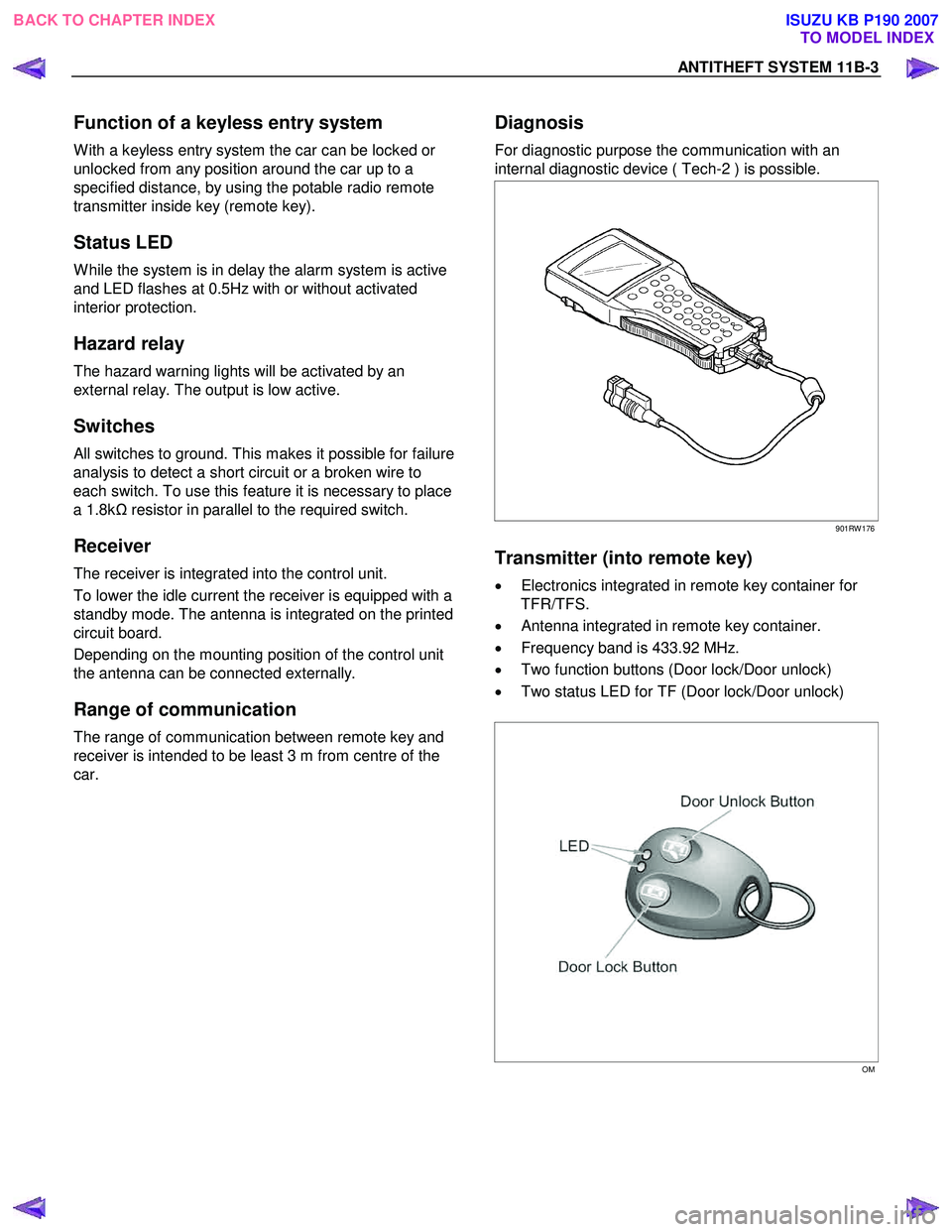
For diagnostic purpose the communication with an
internal diagnostic device ( Tech-2 ) is possible.
901RW 176
Transmitter (into remote key)
• Electronics integrated in remote key container for
TFR/TFS.
• Antenna integrated in remote key container.
• Frequency band is 433.92 MHz.
• Two function buttons (Door lock/Door unlock)
• Two status LED for TF (Door lock/Door unlock)
OM
BACK TO CHAPTER INDEX TO MODEL INDEX
ISUZU KB P190 2007
Page 5958 of 6020
11B-4 ANTITHEFT SYSTEM
Transmitter (into remote key) power
The transmitted power is less than 10 m W .
Battery life time for transmitter power
The minimum life time of battery is 2 years with 15
lock/unlock cycles per day.
W hile the battery is changed, the data retention will be
at least 3 minutes without pressing a button.
Super lock
(Mechanical anti-theft locking system)
To Lock:
All doors must be closed; press the lock button on the
remote control unit again within 10 seconds after
locking or turn key in driver's door lock towards rear of
vehicle again within 10 seconds after locking, then turn
it back to the vertical position and remove.
Lock buttons on all doors are positioned such that doors
cannot be opened.
To unlock:
Press unlock button on remote key or turn key in
driver's door lock towards front of vehicle, then turn it
back to the vertical position and remove. If the key is
used, antitheft alarm sound operate which continues
until ignition switch turn ON. If a problem is found, open
the driver door as necessary.
No proper transmitter is available, what
should be done for the system?
W hen any proper transmitter is not available, a new
transmitter should be programmed. Up to 5 transmitters
can be provided with a scan tool (Tech-2) and by proper
procedure.
In addition to the absence of proper transmitter, it may
happen particular secret code to the particular vehicle is
missing. ln this case, the secret code must be provided
by your organization.
Otherwise transmitter cannot be programmed in any
way.
lf the essential for a scan tool (Tech-2) for programming
and proper software for Tech-2 are not available, there
is no permanent way to fix system. Temporary replace
with new ACU, new ICU and new transmitter without
any secret code can make the system be deactivated,
but it does not last long. Such a replacement does not
solve any condition. Even after replacement, the system
is activated automatically in short time and then no
operation of the vehicle can be made in any way.
Tech-2 should be provided in your organization.
• Security code management
Your organization must keep security codes for all
vehicles as confidential data. Once the security codes
are lost, anybody who have the security code can
access antitheft system. Your organization has
responsibility of any missing vehicles caused by stolen
security code.
• Essential tool (Scan tool: Tech-2)
Your dealership must have Tech-2, and Tech-2 updated
software for immobilizer system.
BACK TO CHAPTER INDEX TO MODEL INDEX
ISUZU KB P190 2007
Page 5979 of 6020
ANTITHEFT SYSTEM 11B-25
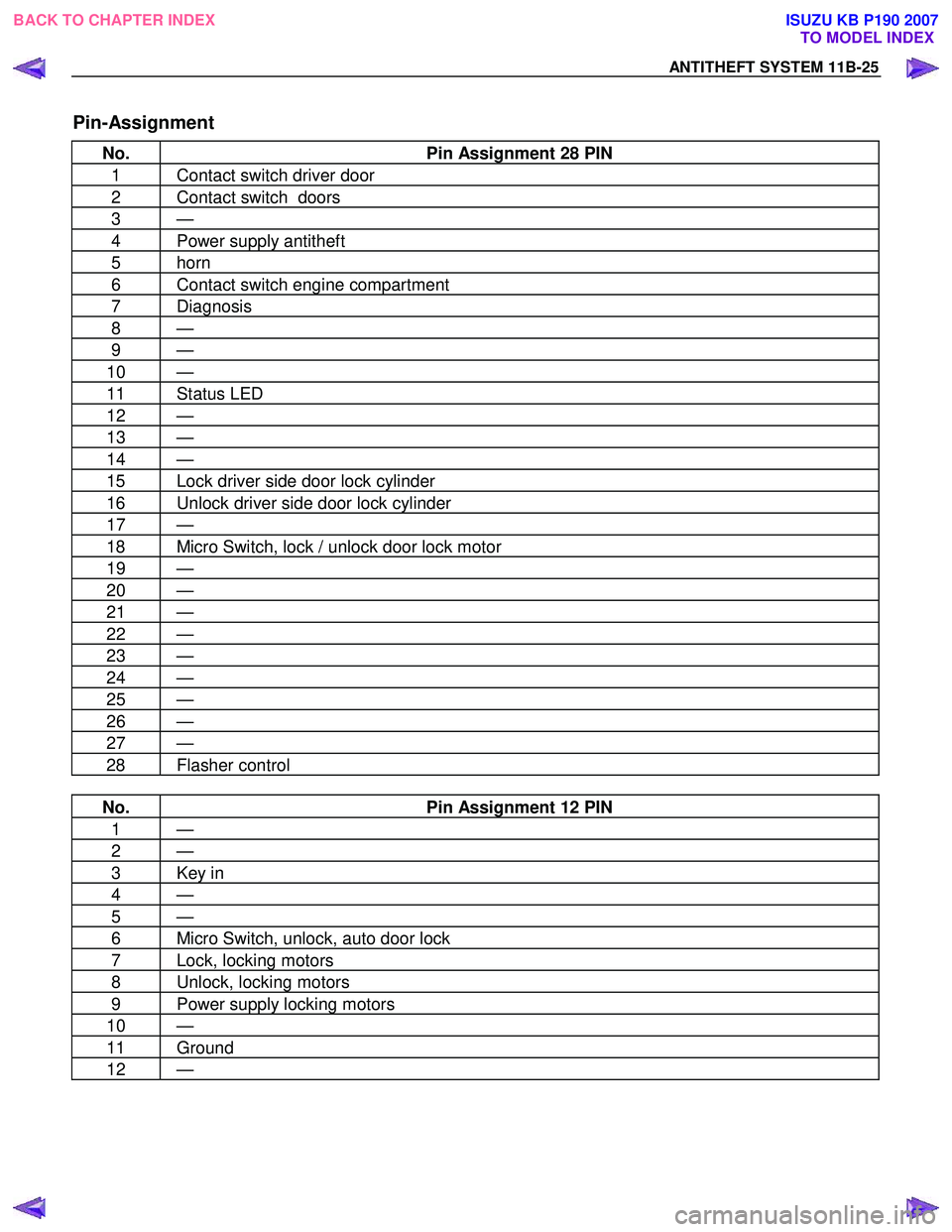
Pin-Assignment
No. Pin Assignment 28 PIN
1 Contact switch driver door
2 Contact switch doors
3 —
4 Power supply antitheft
5 horn
6 Contact switch engine compartment
7 Diagnosis
8 —
9 —
10 —
11 Status LED
12 —
13 —
14 —
15 Lock driver side door lock cylinder
16 Unlock driver side door lock cylinder
17 —
18 Micro Switch, lock / unlock door lock motor
19 —
20 —
21 —
22 —
23 —
24 —
25 —
26 —
27 —
28 Flasher control
No. Pin Assignment 12 PIN
1 —
2 —
3 Key in
4 —
5 —
6 Micro Switch, unlock, auto door lock
7 Lock, locking motors
8 Unlock, locking motors
9 Power supply locking motors
10 —
11 Ground
12 —
BACK TO CHAPTER INDEX
TO MODEL INDEX
ISUZU KB P190 2007
Page 5980 of 6020
11B-26 ANTITHEFT SYSTEM
lmportant information on Programming
Security code
The security code protects the antitheft control unit
against unauthorized programming and data access
from Tech-2. The security code consists of a 4 digit
code number and is programmed into the antitheft
Control Module (ACU).
New control units are not programmed with a security
code.
If the control units are replaced, the security code
entered in the transmitter (into remote key).
Must be programmed into the new control unit with
Tech-2.
The security code can only be programmed with Tech-2
once and must therefore be performed with great care.
Once programmed, the security code cannot be
overwritten. An already used antitheft can be reused in
a different car by initializing the antitheft. After that you
can program the security code again. For initializing
command you need the current security code.
If the antitheft control unit is returned, always enclosed
the security code that is allocated to that control unit. If
this is not done, we can not process the case and the
warranty will not be recognized.
Entering a code
If the Tech-2 display requests that the
• security code
• Vehicle Identification No.
• Country code (Select 213 Germany in all items)
be entered, process as follows;
To input a digit you need to use the up and down
buttons of the Tech-2. By using the numeric buttons the
according digit will be displayed at the current position
and the cursor will move to the next position.
For letters you need to use the up and down buttons of
the Tech-2. The up and down key might be used for
digits as well. By using the up and down buttons the
displayed digit or letter will be increased or decreased.
To move to the next position you need to use the move-
to-right-button.
W ith the two buttons, move-to-right and move-to-left
you can select the position of number you want to
change.
This will allow you to correct a wrong number.
After the number is completed you need to press the
Enter button to accept the number. Correction is now no
longer possible.
Use the OKAY soft key to program the number and the
NOT OKAY soft key to abort the programming.
BACK TO CHAPTER INDEX TO MODEL INDEX
ISUZU KB P190 2007
Page 5982 of 6020
11B-28 ANTITHEFT SYSTEM
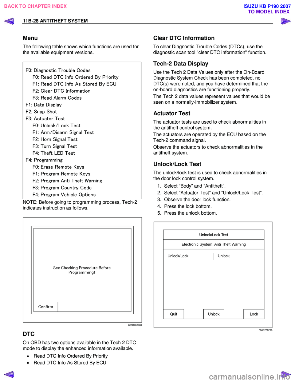
Menu
The following table shows which functions are used for
the available equipment versions.
F0: Diagnostic Trouble Codes
F0: Read DTC Info Ordered By Priority
F1: Read DTC Info As Stored By ECU
F2: Clear DTC Information
F3: Read Alarm Codes
F1: Data Display
F2: Snap Shot
F3: Actuator Test
F0: Unlock/Lock Test
F1: Arm/Disarm Signal Test
F2: Horn Signal Test
F3: Turn Signal Test
F4: Theft LED Test
F4: Programming
F0: Erase Remote Keys
F1: Program Remote Keys
F2: Program Anti Theft Warning
F3: Program Country Code
F4: Program Vehicle Options
NOTE: Before going to programming process, Tech-2
indicates instruction as follows.
060R200289
DTC
On OBD has two options available in the Tech 2 DTC
mode to display the enhanced information available.
• Read DTC Info Ordered By Priority
• Read DTC Info As Stored By ECU
Clear DTC Information
To clear Diagnostic Trouble Codes (DTCs), use the
diagnostic scan tool "clear DTC information" function.
Tech-2 Data Display
Use the Tech 2 Data Values only after the On-Board
Diagnostic System Check has been completed, no
DTC(s) were noted, and you have determined that the
on-board diagnostics are functioning properly.
The Tech 2 data values represent values that would be
seen on a normally-immobilizer system.
Actuator Test
The actuator tests are used to check abnormalities in
the antitheft control system.
The actuators are operated by the ECU based on the
Tech-2 command signal.
Observe the actuators to check abnormalities in the
antitheft system.
Unlock/Lock Test
The unlock/lock test is used to check abnormalities in
the door lock control system.
1. Select “Body” and “Antitheft”.
2. Select ”Actuator Test” and “Unlock/Lock Test”.
3. Observe the door lock function.
4. Press the lock bottom.
5. Press the unlock bottom.
060R200279
BACK TO CHAPTER INDEX TO MODEL INDEX
ISUZU KB P190 2007
Page 5983 of 6020
ANTITHEFT SYSTEM 11B-29
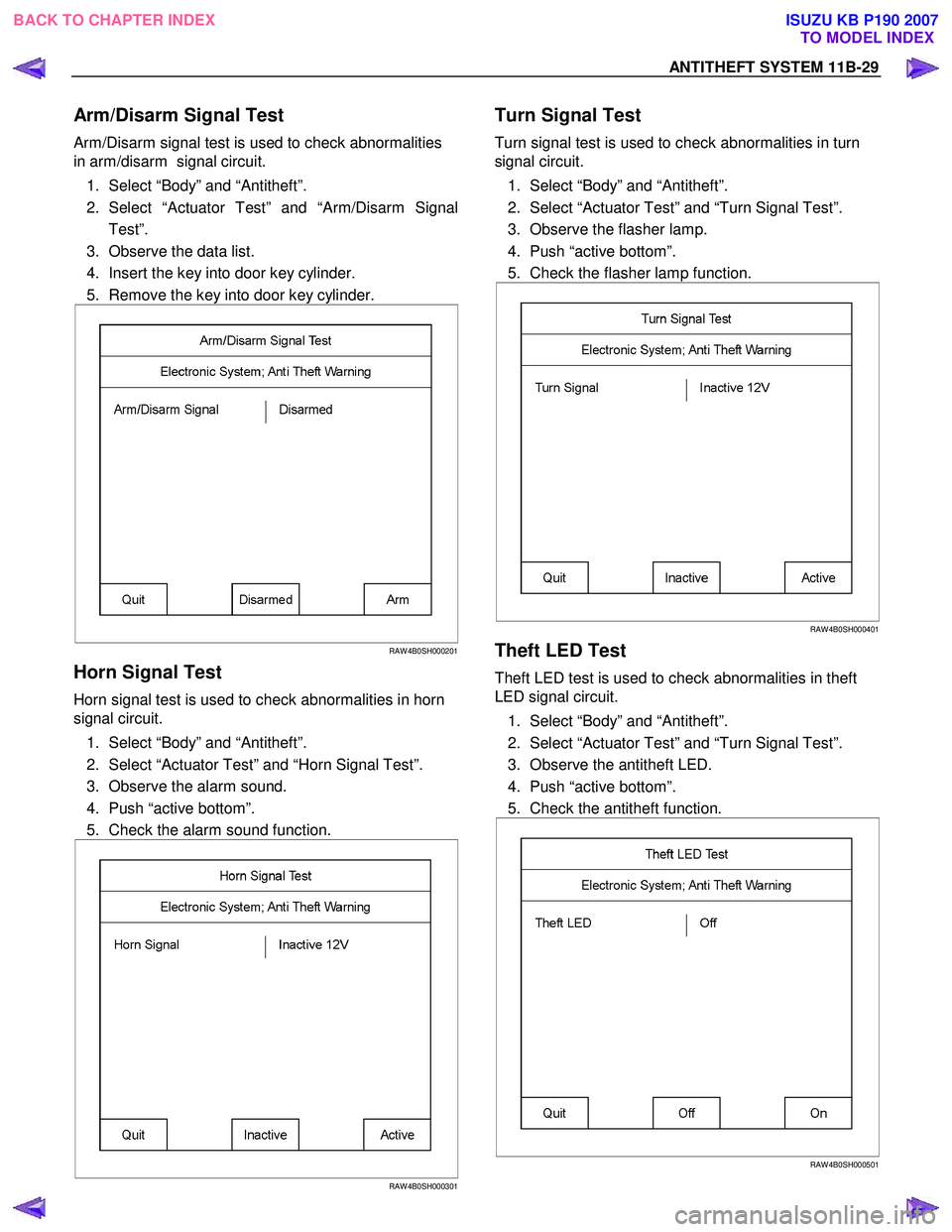
Arm/Disarm Signal Test
Arm/Disarm signal test is used to check abnormalities
in arm/disarm signal circuit.
1. Select “Body” and “Antitheft”.
2. Select “Actuator Test” and “
Arm/Disarm Signal
Test”.
3. Observe the data list.
4. Insert the key into door key cylinder.
5. Remove the key into door key cylinder.
RAW 4B0SH000201
Horn Signal Test
Horn signal test is used to check abnormalities in horn
signal circuit.
1. Select “Body” and “Antitheft”.
2. Select “Actuator Test” and “Horn Signal Test”.
3. Observe the alarm sound.
4. Push “active bottom”.
5. Check the alarm sound function.
RAW 4B0SH000301
Turn Signal Test
Turn signal test is used to check abnormalities in turn
signal circuit.
1. Select “Body” and “Antitheft”.
2. Select “Actuator Test” and “Turn Signal Test”.
3. Observe the flasher lamp.
4. Push “active bottom”.
5. Check the flasher lamp function.
RAW 4B0SH000401
Theft LED Test
Theft LED test is used to check abnormalities in theft
LED signal circuit.
1. Select “Body” and “Antitheft”.
2. Select “Actuator Test” and “Turn Signal Test”.
3. Observe the antitheft LED.
4. Push “active bottom”.
5. Check the antitheft function.
RAW 4B0SH000501
BACK TO CHAPTER INDEX
TO MODEL INDEX
ISUZU KB P190 2007
Page 5984 of 6020
11B-30 ANTITHEFT SYSTEM
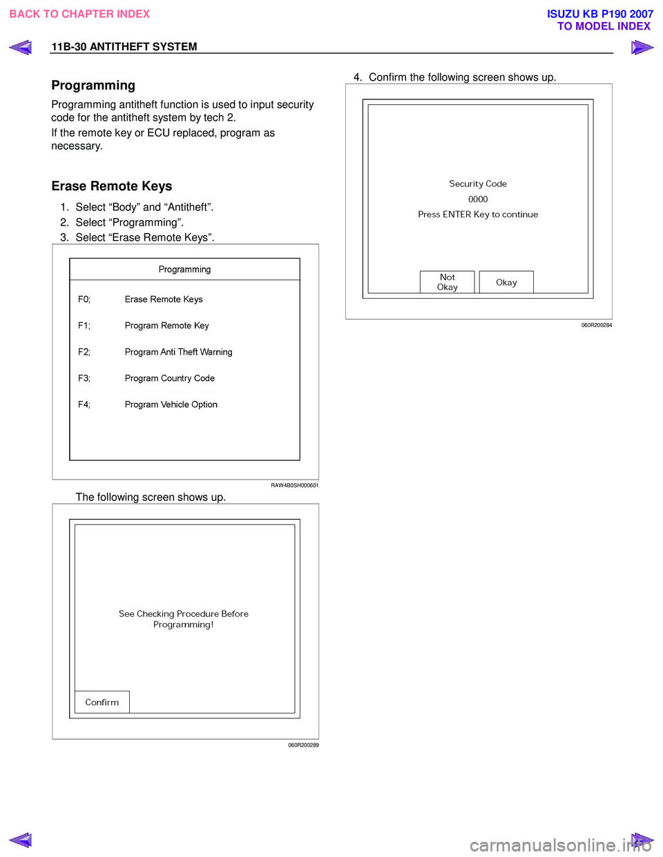
Programming
Programming antitheft function is used to input security
code for the antitheft system by tech 2.
If the remote key or ECU replaced, program as
necessary.
Erase Remote Keys
1. Select “Body” and “Antitheft”.
2. Select “Programming”.
3. Select “Erase Remote Keys”.
RAW 4B0SH000601
The following screen shows up.
060R200289
4. Confirm the following screen shows up.
060R200284
BACK TO CHAPTER INDEX TO MODEL INDEX
ISUZU KB P190 2007
Page 5985 of 6020
ANTITHEFT SYSTEM 11B-31
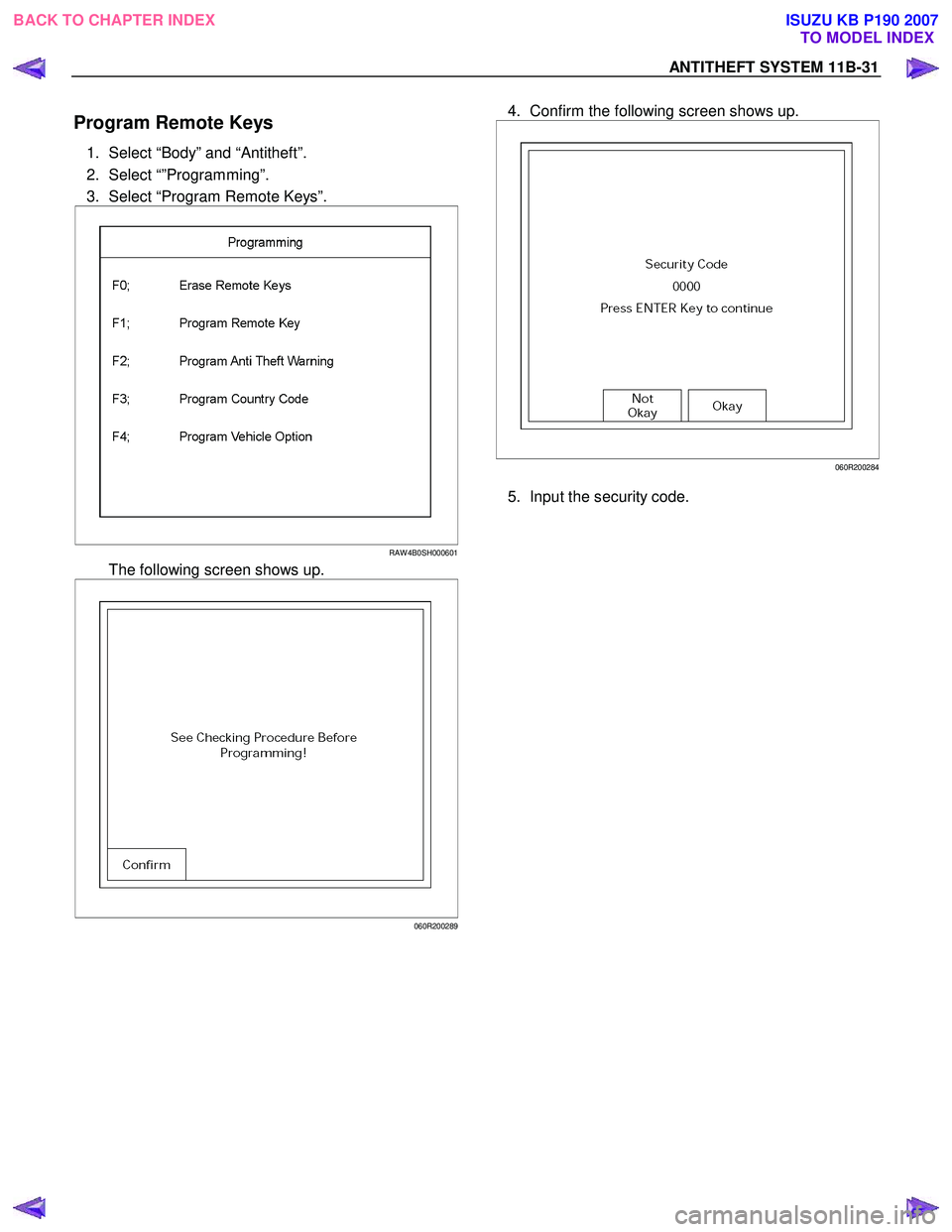
Program Remote Keys
1. Select “Body” and “Antitheft”.
2. Select “”Programming”.
3. Select “Program Remote Keys”.
RAW 4B0SH000601
The following screen shows up.
060R200289
4. Confirm the following screen shows up.
060R200284
5. Input the security code.
BACK TO CHAPTER INDEX TO MODEL INDEX
ISUZU KB P190 2007