2007 ISUZU KB P190 BATTERY
[x] Cancel search: BATTERYPage 1967 of 6020
6E-350 ENGINE CONTROL SYSTEM (4JK1/4JJ1)
• The hardware key is plugged into the computerport.
• Vehicle system voltage: - There are no charging system concerns. Allcharging system concerns must be repaired
before programming the ECM.
- The battery voltage is greater than 12 volts but less than 16 volts. The battery must be fully
charged before programming the ECM.
- A battery charger is NOT connected to the vehicles battery. Incorrect system voltage or
voltage fluctuations from a battery charger may
cause programming failure or ECM damage.
- Turn OFF or disable any system that may put a load on the vehicles battery. Turn OFF or
disable systems such as:
◊ Heating, ventilation, and air conditioning
(HVAC) systems
◊ Headlights
◊ Room lights
◊ Accessory equipment
• The ignition switch is in the proper position. The scan tool prompts you to turn ON the ignition, with
the engine OFF. DO NOT change the position of
the ignition switch during the programming
procedure unless instructed to do so.
• All tool connections are secure: - The RS-232 cable
- The connection at the DLC
- The voltage supply circuits
• DO NOT disturb the tool harnesses while programming. If an interruption occurs during the
programming procedure, programming failure or
ECM damage may occur.
• If you are performing the Pass-Thru programming procedure using a notebook computer without the
power cord, ensure that the internal battery is fully
charged.
Service Programming System (SPS)
(Remote Procedure)
Notice: Some module will not accept SPS remote
procedure using 10MB PCMCIA card. In such case,
use 32MB PCMCIA card or SPS pass-thru procedure.
The Remote SPS method is a three-step process that
involves the following procedures:
1. Connecting the scan tool to the vehicle and obtaining the information from the ECM.
2. Connecting the scan tool to the terminal and downloading a new calibration file from the
terminal into the scan tool memory.
3. Reconnecting the scan tool to the vehicle and uploading the new calibration file into the ECM. Performing the Remote Procedure
1. Connect a scan tool to the vehicle and obtain the ECM information using the following procedure:
Notice: Ensure the ECM is installed in the vehicle and
the battery is fully charged before programming.
a. Install a scan tool.
b. Turn ON the ignition, with the engine OFF.
c. Select Service Programming System (SPS) > Request Info.
d. If there is already stored in the scan tool, the existing data is displayed on the screen. The
scan tool asks user to keep existing data "Keep
Data" or "Continue" to request new vehicle
information from the ECM. If there is no data in
the scan tool, it will immediately start vehicle
identification.
e. Select the vehicle description by following the on-screen instructions based on stamped VIN
or affixed VIN plate on the vehicle.
f. During obtaining information, the scan tool is receiving information from all modules at the
same time. But only ECM information is
displayed on the screen.
g. Turn OFF all accessories and press "Okay".
h. Verify that the correct VIN is displayed on the scan tool. If the VIN is incorrect or no VIN,
record the correct VIN.
2. Turn OFF the ignition.
3. Turn OFF the scan tool and disconnect from the vehicle.
4. Transfer the data from the terminal to the scan tool using the following procedure:
Notice: The TIS supports service programming with
the Tech 2 scan tool only.
a. Connect the scan tool to the terminal.
b. Launch the TIS application.
c. Select the Service Programming System at the main screen.
d. Highlight the following information on the Select Diagnostic Tool and Programming Process
screen, then click "Next".
• Select Diagnostic Tool - Tech 2
• Select Programming Process - Identify whether an existing ECM is being
reprogrammed or an ECM is being replaced
with a new one
• Select ECU Location - Vehicle
e. Verify the connections on the Preparing for Communication screen, then click "Next".
f. Verify the VIN on the Validate Vehicle Identification Number (VIN) screen, then click
"Next".
BACK TO CHAPTER INDEX
TO MODEL INDEX
ISUZU KB P190 2007
Page 1970 of 6020
ENGINE CONTROL SYSTEM (4JK1/4JJ1) 6E-353
Description and Operation
Engine Control Module (ECM) Description
Engine Control Module (ECM) Service Precautions
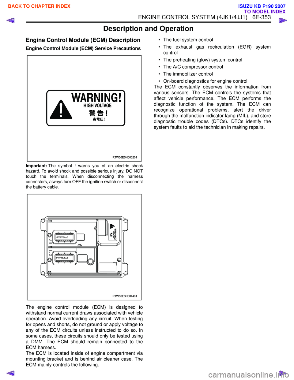
Important:The symbol ! warns you of an electric shock
hazard. To avoid shock and possible serious injury, DO NOT
touch the terminals. When disconnecting the harness
connectors, always turn OFF the ignition switch or disconnect
the battery cable.
The engine control module (ECM) is designed to
withstand normal current draws associated with vehicle
operation. Avoid overloading any circuit. When testing
for opens and shorts, do not ground or apply voltage to
any of the ECM circuits unless instructed to do so. In
some cases, these circuits should only be tested using
a DMM. The ECM should remain connected to the
ECM harness.
The ECM is located inside of engine compartment via
mounting bracket and is behind air cleaner case. The
ECM mainly controls the following. • The fuel system control
• The exhaust gas recirculation (EGR) system control
• The preheating (glow) system control
• The A/C compressor control
• The immobilizer control
• On-board diagnostics for engine control
The ECM constantly observes the information from
various sensors. The ECM controls the systems that
affect vehicle performance. The ECM performs the
diagnostic function of the system. The ECM can
recognize operational problems, alert the driver
through the malfunction indicator lamp (MIL), and store
diagnostic trouble codes (DTCs). DTCs identify the
system faults to aid the technician in making repairs.
RTW56ESH000201
RTW56ESH004401
BACK TO CHAPTER INDEX
TO MODEL INDEX
ISUZU KB P190 2007
Page 1971 of 6020
6E-354 ENGINE CONTROL SYSTEM (4JK1/4JJ1)
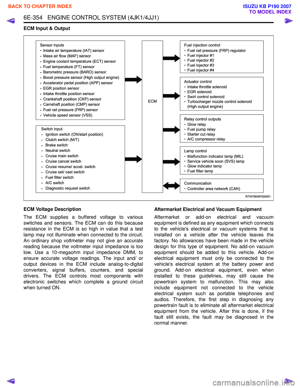
ECM Input & Output
ECM Voltage Description
The ECM supplies a buffered voltage to various
switches and sensors. The ECM can do this because
resistance in the ECM is so high in value that a test
lamp may not illuminate when connected to the circuit.
An ordinary shop voltmeter may not give an accurate
reading because the voltmeter input impedance is too
low. Use a 10-megaohm input impedance DMM, to
ensure accurate voltage readings. The input and/ or
output devices in the ECM include analog-to-digital
converters, signal buffers, counters, and special
drivers. The ECM controls most components with
electronic switches which complete a ground circuit
when turned ON. Aftermarket Electrical and Vacuum Equipment
Aftermarket or add-on electrical and vacuum
equipment is defined as any equipment which connects
to the vehicle's electrical or vacuum systems that is
installed on a vehicle after the vehicle leaves the
factory. No allowances have been made in the vehicle
design for this type of equipment. No add-on vacuum
equipment should be added to this vehicle. Add-on
electrical equipment must only be connected to the
vehicle's electrical system at the battery power and
ground. Add-on electrical equipment, even when
installed to these guidelines, may still cause the
powertrain system to malfunction. This may also
include equipment not connected to the vehicle
electrical system such as portable telephones and
audios. Therefore, the first step in diagnosing any
powertrain fault is to eliminate all aftermarket electrical
equipment from the vehicle. After this is done, if the
fault still exists, the fault may be diagnosed in the
normal manner.
RTW76EMF000501
Sensor inputs
· Intake air temperature (IAT) sensor
· Mass air flow (MAF) sensor
· Engine coolant temperature (ECT) sensor
· Fuel temperature (FT) sensor
· Barometric pressure (BARO) sensor
· Boost pressure sensor (High output engine)
· Accelerator pedal position (APP) sensor
· EGR position sensor
· Intake throttle position sensor
· Crankshaft position (CKP) sensor
· Camshaft position (CMP) sensor
· Fuel rail pressure (FRP) sensor
· Vehicle speed sensor (VSS)
Switch input
· Ignition switch (ON/start position)
· Clutch switch (M/T)
· Brake switch
· Neutral switch
· Cruise main switch
· Cruise cancel switch
· Cruise resume/ accel. switch
· Cruise set/ cast switch
· Fuel filter switch
· A/C switch
· Diagnostic request switch
Fuel injection control
· Fuel rail pressure (FRP) regulator
· Fuel injector #1
· Fuel injector #2
· Fuel injector #3
· Fuel injector #4
Relay control outputs
· Glow relay
· Fuel pump relay
· Starter cut relay
· A/C compressor relay
Lamp control
· Malfunction indicator lamp (MIL)
· Service vehicle soon (SVS) lamp
· Glow indicator lamp
· Fuel filter lamp
Communication
· Controller area network (CAN)
Actuator control
· Intake throttle solenoid
· EGR solenoid
· Swirl control solenoid
· Turbocharger nozzle control solenoid
(High output engine)ECM
BACK TO CHAPTER INDEX
TO MODEL INDEX
ISUZU KB P190 2007
Page 2002 of 6020
6-2 ENGINE DIAGNOSIS (C24SE)
Engine Diagnosis
Hard Starting
1.Starting Motor Does Not Turn Over
Trouble Shooting Procedure
Turn on headlights and starter switch.
Condition Possible cause Correction
Headlights go out or dim
considerably Battery run down or under
charged Recharge or replace battery
Terminals poorly connected Clean battery posts and terminals
and connect properly
Starting motor coil circuit shorted Overhaul or replace
Starting motor defective Overhaul or replace
2.Ignition Trouble - Starting Motor Turns Over But Engine Does Not Start
Spark Test Disconnect a high tension cable from any spark plug.
Connect the spark plug tester (use commercially
available tool), crank the engine, and check if a spark is
generated in the spark plug tester. Before cranking the
engine, make sure that the spark plug tester is properly
grounded. To avoid electrical shock, do not touch the
high tension cable while the engine is running.
Condition Possible cause Correction
Spark jumps across gap Spark plug defective Clean, adjust spark gap or replace
Spark plug wire in correct Connect properly or replace
Ignition timing incorrect Refer to Ignition System
Fuel not reaching fuel injector(s)
or engine Refer to item 3 (Trouble in fuel
system)
Valve timing incorrect Adjust
Engine lacks compression Refer to item 4 (Engine lacks
compression)
No sparking takes place Ignition coil disconnected or
broken Connect properly or replace
Electronic Ignition System with
module Replace
Poor connections in engine
harness Correct
Engine Control Module cable
disconnected or defective Correct or replace
BACK TO CHAPTER INDEX
TO MODEL INDEX
ISUZU KB P190 2007
Page 2018 of 6020
6A-4 ENGINE MECHANICAL (C24SE)
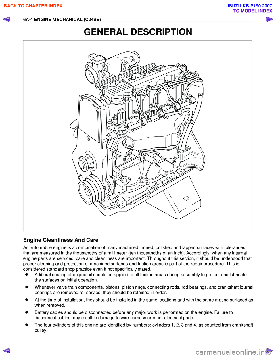
GENERAL DESCRIPTION
Engine Cleanliness And Care
An automobile engine is a combination of many machined, honed, polished and lapped surfaces with tolerances
that are measured in the thousandths of a millimeter (ten thousandths of an inch). Accordingly, when any internal
engine parts are serviced, care and cleanliness are important. Throughout this section, it should be understood that
proper cleaning and protection of machined surfaces and friction areas is part of the repair procedure. This is
considered standard shop practice even if not specifically stated.
�z A liberal coating of engine oil should be applied to all friction areas during assembly to protect and lubricate
the surfaces on initial operation.
�z W henever valve train components, pistons, piston rings, connecting rods, rod bearings, and crankshaft journal
bearings are removed for service, they should be retained in order.
�z
At the time of installation, they should be installed in the same locations and with the same mating surfaced as
when removed.
�z Battery cables should be disconnected before any major work is performed on the engine. Failure to
disconnect cables may result in damage to wire harness or other electrical parts.
�z The four cylinders of this engine are identified by numbers; cylinders 1, 2, 3 and 4, as counted from crankshaft
pulley.
BACK TO CHAPTER INDEX
TO MODEL INDEX
ISUZU KB P190 2007
Page 2019 of 6020
ENGINE MECHANICAL (C24SE) 6A-5
General Information on Engine Service
The following information on engine service should be noted carefully, as it is important in preventing damage and
contributing to reliable engine performance:
�z W hen raising or supporting the engine for any reason, do not use a jack under the oil pan. Due to the small
clearance between the oil pan and the oil pump strainer, jacking against the oil pan may cause damage to the
oil pick up unit.
�z The 12-volt electrical system is capable of damaging circuits. W hen performing any work where electrical
terminals could possible be grounded, the ground cable of the battery should be disconnected at the battery.
�z Any time the intake air duct or air cleaner is removed, the intake opening should be covered. This will protect
against accidental entrance of foreign material into the cylinder which could cause extensive damage when
the engine is started.
Cylinder Block
The cylinder block is made of cast iron. The crankshaft is supported by five bearings. The bearing cap is made of
nodular cast iron.
Cylinder Head
The cylinder head is made of aluminum alloy casting with a spark plug in the center.
Valve Train
Valve system is a single over head camshaft.
The valves clearance adjustment are hydraulic.
Hydraulic valve lifter adjustment, no adjustment necessary.
Intake Manifold
The intake manifold is made of aluminum alloy.
Exhaust Manifold
The exhaust manifold is made of high Si-Mo nodular iron.
Pistons and Connecting Rods
Aluminum pistons are used after selecting the grade that meets the cylinder bore diameter. Each piston has two
compression rings and one oil ring. The piston pin is made of cast hardened steel. The connecting rod bearings are
made of modular cast iron. The connecting rod bearings are made of steel backed with tri-metal babbitt metal.
Crankshaft and Bearings
The crank shaft is made of modular cast iron. Pins and journal are graded for correct size selection for their bearing.
BACK TO CHAPTER INDEX
TO MODEL INDEX
ISUZU KB P190 2007
Page 2025 of 6020
ENGINE MECHANICAL (C24SE) 6A-11
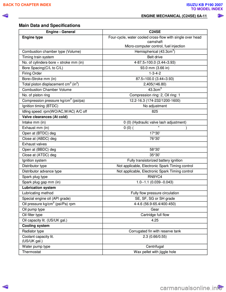
Main Data and Specifications
Engine - General C24SE
Engine type Four-cycle, water cooled cross-flow with single over head
camshaft
Micro-computer control, fuel injection
Combustion chamber type (Volume) Hemispherical (43.3cm3)
Timing train system Belt drive
No. of cylinders-bore × stroke mm (in) 4-87.5 ×100.0 (3.44 ×3.93)
Bore Spacing(C/L to C/L) 93.0 mm (3.66 in)
Firing Order 1-3-4-2
Bore×Stroke mm (in) 87.5 ×100.0 (3.44 ×3.93)
Total piston displacement cm3 (in3) 2,405(146.80)
Combustion Chamber Volume 43.3cm3
No. of piston ring Compression ring: 2, Oil ring: 1
Compression pressure kg/cm2 (psi/pa) 12.2-16.3 (174-232/1200-1600)
Ignition timing (BTDC) No adjustment
Idling speed: rpm(W O/AC,W /AC) A/C off 825
Valve clearances (At cold)
Intake mm (in) 0 (0) (Hydraulic valve lash adjustment)
Exhaust mm (in) 0 (0) ( " )
Open at (BTDC) deg 17°30’
Close at (ABDC) deg 76°30’
Exhaust valves
Open at (BBDC) deg 58°30’
Close at (ATDC) deg 35°30’
Ignition system Fully transistorized battery ignition
Distributor type Not applicable, Electronic Spark Timing control
Distributor advance type Not applicable, Electronic Spark Timing control
Spark plug type RN9YC4
Spark plug gap mm (in) 1.0--1.1 (0.039--0.043)
Lubrication system
Lubricating method Fully flow pressure circulation
Special engine oil (API grade) SE, SF, SG or SH grade
Oil pressure kg/cm2 (psi/Pa) rpm 4-4.6 (56.9-65.4/400-450)
Oil pump type Gear
Oil filter type Cartridge full flow
Oil capacity lit. (US/UK gal.) 4.25
Cooling system
Radiator type Corrugated fin with reserve tank
Coolant capacity lit.
(US/UK gal.) 2.3 (0.66/0.55)
W ater pump type
Centrifugal
Thermostat W ax pellet with jiggle hole
BACK TO CHAPTER INDEX
TO MODEL INDEX
ISUZU KB P190 2007
Page 2026 of 6020
6A-12 ENGINE MECHANICAL (C24SE)
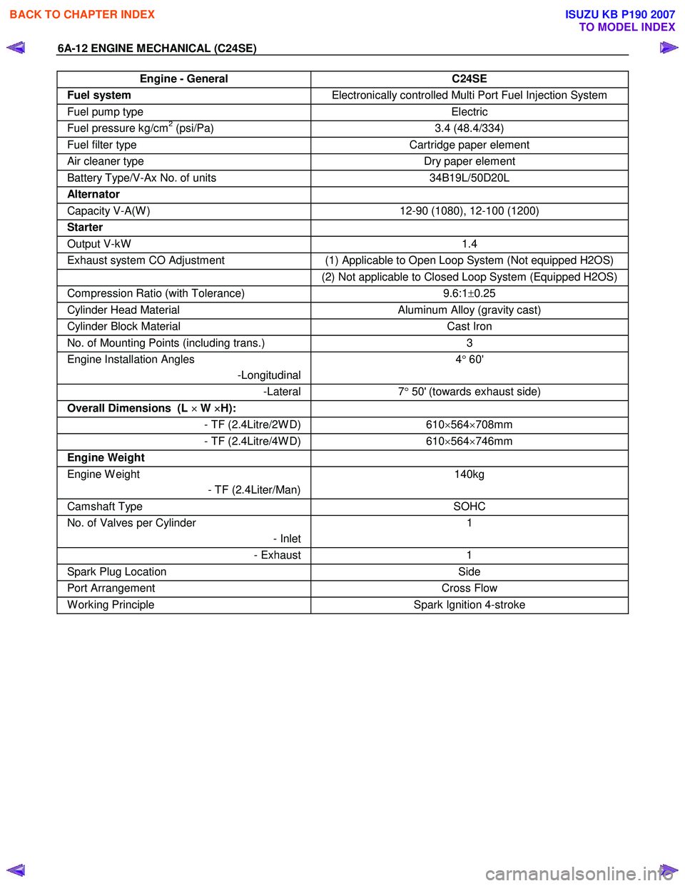
Engine - General C24SE
Fuel system Electronically controlled Multi Port Fuel Injection System
Fuel pump type Electric
Fuel pressure kg/cm2 (psi/Pa) 3.4 (48.4/334)
Fuel filter type Cartridge paper element
Air cleaner type Dry paper element
Battery Type/V-Ax No. of units 34B19L/50D20L
Alternator
Capacity V-A(W ) 12-90 (1080), 12-100 (1200)
Starter
Output V-kW 1.4
Exhaust system CO Adjustment (1) Applicable to Open Loop System (Not equipped H2OS)
(2) Not applicable to Closed Loop System (Equipped H2OS)
Compression Ratio (with Tolerance) 9.6:1±0.25
Cylinder Head Material Aluminum Alloy (gravity cast)
Cylinder Block Material Cast Iron
No. of Mounting Points (including trans.) 3
Engine Installation Angles
-Longitudinal 4
° 60'
-Lateral 7° 50' (towards exhaust side)
Overall Dimensions (L ×
××
×
W ×
××
×
H):
- TF (2.4Litre/2W D)610×564 ×708mm
- TF (2.4Litre/4W D) 610×564 ×746mm
Engine Weight
Engine W eight
- TF (2.4Liter/Man) 140kg
Camshaft Type
SOHC
No. of Valves per Cylinder
- Inlet1
- Exhaust
1
Spark Plug Location Side
Port Arrangement Cross Flow
W orking Principle Spark Ignition 4-stroke
BACK TO CHAPTER INDEX
TO MODEL INDEX
ISUZU KB P190 2007