2007 ISUZU KB P190 BATTERY
[x] Cancel search: BATTERYPage 1926 of 6020
ENGINE CONTROL SYSTEM (4JK1/4JJ1) 6E-309
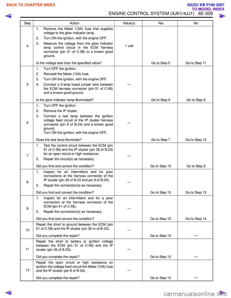
41. Remove the Meter (10A) fuse that supplies
voltage to the glow indicator lamp.
2. Turn ON the ignition, with the engine OFF.
3. Measure the voltage from the glow indicator lamp control circuit in the ECM harness
connector (pin 51 of C-58) to a known good
ground.
Is the voltage less than the specified value? 1 volt
Go to Step 5 Go to Step 11
5 1. Turn OFF the ignition.
2. Reinstall the Meter (10A) fuse.
3. Turn ON the ignition, with the engine OFF.
4. Connect a 3-amp fused jumper wire between the ECM harness connector (pin 51 of C-58)
and a known good ground.
Is the glow indicator lamp illuminated? —
Go to Step 9 Go to Step 6
6 1. Turn OFF the ignition.
2. Remove the IP cluster.
3. Connect a test lamp between the ignition voltage feed circuit of the IP cluster harness
connector (pin 8 of B-24) and a known good
ground.
Turn ON the ignition, with the engine OFF.
Does the test lamp illuminate? —
Go to Step 7 Go to Step 12
7 1. Test the control circuit between the ECM (pin
51 of C-58) and the IP cluster (pin 35 of B-23)
for an open circuit or high resistance.
2. Repair the circuit(s) as necessary.
Did you find and correct the condition? —
Go to Step 15 Go to Step 8
8 1. Inspect for an intermittent and for poor
connections at the harness connector of the
IP cluster (pin 35 of B-23 and pin 8 of B-24).
2. Repair the connection(s) as necessary.
Did you find and correct the condition? —
Go to Step 15 Go to Step 13
9 1. Inspect for an intermittent and for a poor
connection at the harness connector of the
ECM (pin 51 of C-58).
2. Repair the connection(s) as necessary.
Did you find and correct the condition? —
Go to Step 15 Go to Step 14
10 Repair the short to ground between the ECM (pin
51 of C-58) and the IP cluster (pin 35 or of B-23).
Did you complete the repair? —
Go to Step 15
—
11Repair the short to battery or ignition voltage
between the ECM (pin 51 of C-58) and the IP
cluster (pin 35 of B-23).
Did you complete the repair? —
Go to Step 15
—
12Repair the open circuit or high resistance on
ignition the voltage feed circuit the Meter (10A) fuse
and the IP cluster (pin 8 of B-24).
Did you complete the repair? —
Go to Step 15
—
Step Action Value(s)Yes No
BACK TO CHAPTER INDEX
TO MODEL INDEX
ISUZU KB P190 2007
Page 1928 of 6020
ENGINE CONTROL SYSTEM (4JK1/4JJ1) 6E-311
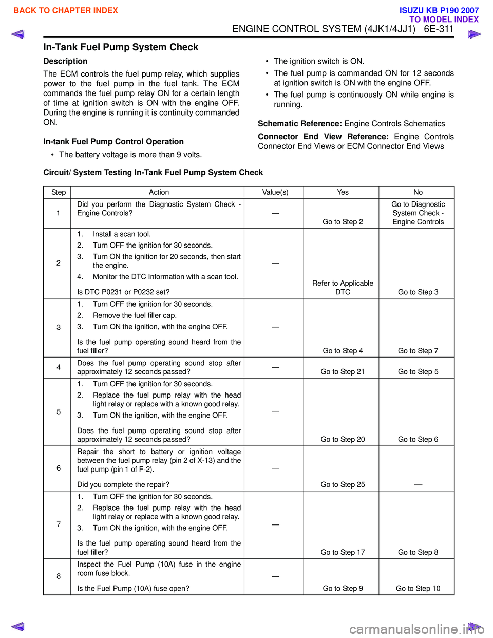
In-Tank Fuel Pump System Check
Description
The ECM controls the fuel pump relay, which supplies
power to the fuel pump in the fuel tank. The ECM
commands the fuel pump relay ON for a certain length
of time at ignition switch is ON with the engine OFF.
During the engine is running it is continuity commanded
ON.
In-tank Fuel Pump Control Operation • The battery voltage is more than 9 volts. • The ignition switch is ON.
• The fuel pump is commanded ON for 12 seconds at ignition switch is ON with the engine OFF.
• The fuel pump is continuously ON while engine is running.
Schematic Reference: Engine Controls Schematics
Connector End View Reference: Engine Controls
Connector End Views or ECM Connector End Views
Circuit/ System Testing In-Tank Fuel Pump System Check
Step Action Value(s)Yes No
1 Did you perform the Diagnostic System Check -
Engine Controls? —
Go to Step 2 Go to Diagnostic
System Check -
Engine Controls
2 1. Install a scan tool.
2. Turn OFF the ignition for 30 seconds.
3. Turn ON the ignition for 20 seconds, then start the engine.
4. Monitor the DTC Information with a scan tool.
Is DTC P0231 or P0232 set? —
Refer to Applicable DTC Go to Step 3
3 1. Turn OFF the ignition for 30 seconds.
2. Remove the fuel filler cap.
3. Turn ON the ignition, with the engine OFF.
Is the fuel pump operating sound heard from the
fuel filler? —
Go to Step 4 Go to Step 7
4 Does the fuel pump operating sound stop after
approximately 12 seconds passed? —
Go to Step 21 Go to Step 5
5 1. Turn OFF the ignition for 30 seconds.
2. Replace the fuel pump relay with the head light relay or replace with a known good relay.
3. Turn ON the ignition, with the engine OFF.
Does the fuel pump operating sound stop after
approximately 12 seconds passed? —
Go to Step 20 Go to Step 6
6 Repair the short to battery or ignition voltage
between the fuel pump relay (pin 2 of X-13) and the
fuel pump (pin 1 of F-2).
Did you complete the repair? —
Go to Step 25
—
71. Turn OFF the ignition for 30 seconds.
2. Replace the fuel pump relay with the head light relay or replace with a known good relay.
3. Turn ON the ignition, with the engine OFF.
Is the fuel pump operating sound heard from the
fuel filler? —
Go to Step 17 Go to Step 8
8 Inspect the Fuel Pump (10A) fuse in the engine
room fuse block.
Is the Fuel Pump (10A) fuse open? —
Go to Step 9 Go to Step 10
BACK TO CHAPTER INDEX
TO MODEL INDEX
ISUZU KB P190 2007
Page 1929 of 6020
6E-312 ENGINE CONTROL SYSTEM (4JK1/4JJ1)
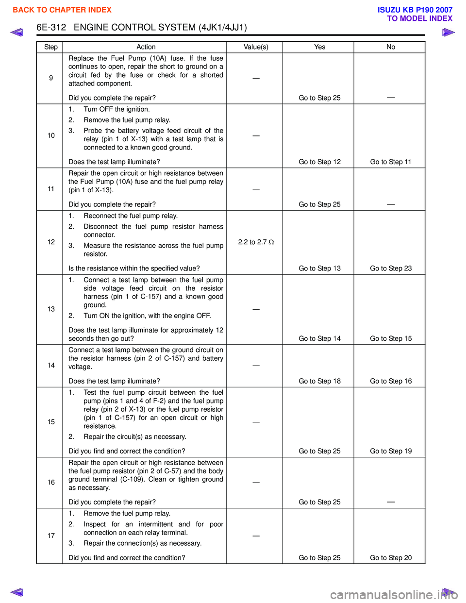
9Replace the Fuel Pump (10A) fuse. If the fuse
continues to open, repair the short to ground on a
circuit fed by the fuse or check for a shorted
attached component.
Did you complete the repair? —
Go to Step 25
—
101. Turn OFF the ignition.
2. Remove the fuel pump relay.
3. Probe the battery voltage feed circuit of the relay (pin 1 of X-13) with a test lamp that is
connected to a known good ground.
Does the test lamp illuminate? —
Go to Step 12 Go to Step 11
11 Repair the open circuit or high resistance between
the Fuel Pump (10A) fuse and the fuel pump relay
(pin 1 of X-13).
Did you complete the repair? —
Go to Step 25
—
121. Reconnect the fuel pump relay.
2. Disconnect the fuel pump resistor harness connector.
3. Measure the resistance across the fuel pump resistor.
Is the resistance within the specified value? 2.2 to 2.7
Ω
Go to Step 13 Go to Step 23
13 1. Connect a test lamp between the fuel pump
side voltage feed circuit on the resistor
harness (pin 1 of C-157) and a known good
ground.
2. Turn ON the ignition, with the engine OFF.
Does the test lamp illuminate for approximately 12
seconds then go out? —
Go to Step 14 Go to Step 15
14 Connect a test lamp between the ground circuit on
the resistor harness (pin 2 of C-157) and battery
voltage.
Does the test lamp illuminate? —
Go to Step 18 Go to Step 16
15 1. Test the fuel pump circuit between the fuel
pump (pins 1 and 4 of F-2) and the fuel pump
relay (pin 2 of X-13) or the fuel pump resistor
(pin 1 of C-157) for an open circuit or high
resistance.
2. Repair the circuit(s) as necessary.
Did you find and correct the condition? —
Go to Step 25 Go to Step 19
16 Repair the open circuit or high resistance between
the fuel pump resistor (pin 2 of C-57) and the body
ground terminal (C-109). Clean or tighten ground
as necessary.
Did you complete the repair? —
Go to Step 25
—
171. Remove the fuel pump relay.
2. Inspect for an intermittent and for poor connection on each relay terminal.
3. Repair the connection(s) as necessary.
Did you find and correct the condition? —
Go to Step 25 Go to Step 20
Step
Action Value(s)Yes No
BACK TO CHAPTER INDEX
TO MODEL INDEX
ISUZU KB P190 2007
Page 1934 of 6020
ENGINE CONTROL SYSTEM (4JK1/4JJ1) 6E-317
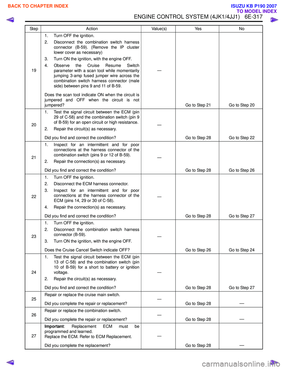
191. Turn OFF the ignition.
2. Disconnect the combination switch harness connector (B-59). (Remove the IP cluster
lower cover as necessary)
3. Turn ON the ignition, with the engine OFF.
4. Observe the Cruise Resume Switch parameter with a scan tool while momentarily
jumping 3-amp fused jumper wire across the
combination switch harness connector (male
side) between pins 9 and 11 of B-59.
Does the scan tool indicate ON when the circuit is
jumpered and OFF when the circuit is not
jumpered? —
Go to Step 21 Go to Step 20
20 1. Test the signal circuit between the ECM (pin
29 of C-58) and the combination switch (pin 9
of B-59) for an open circuit or high resistance.
2. Repair the circuit(s) as necessary.
Did you find and correct the condition? —
Go to Step 28 Go to Step 22
21 1. Inspect for an intermittent and for poor
connections at the harness connector of the
combination switch (pins 9 or 12 of B-59).
2. Repair the connection(s) as necessary.
Did you find and correct the condition? —
Go to Step 28 Go to Step 26
22 1. Turn OFF the ignition.
2. Disconnect the ECM harness connector.
3. Inspect for an intermittent and for poor connections at the harness connector of the
ECM (pins 14, 29 or 30 of C-58).
4. Repair the connection(s) as necessary.
Did you find and correct the condition? —
Go to Step 28 Go to Step 27
23 1. Turn OFF the ignition.
2. Disconnect the combination switch harness connector (B-59).
3. Turn ON the ignition, with the engine OFF.
Does the Cruise Cancel Switch indicate OFF? —
Go to Step 26 Go to Step 24
24 1. Test the signal circuit between the ECM (pin
13 of C-58) and the combination switch (pin
10 of B-59) for a short to battery or ignition
voltage.
2. Repair the circuit(s) as necessary.
Did you find and correct the condition? —
Go to Step 28 Go to Step 27
25 Repair or replace the cruise main switch.
Did you complete the repair or replacement? —
Go to Step 28
—
26Repair or replace the combination switch.
Did you complete the repair or replacement? —
Go to Step 28—
27Important
: Replacement ECM must be
programmed and learned.
Replace the ECM. Refer to ECM Replacement.
Did you complete the replacement? —
Go to Step 28
—
Step Action Value(s)Yes No
BACK TO CHAPTER INDEX
TO MODEL INDEX
ISUZU KB P190 2007
Page 1935 of 6020
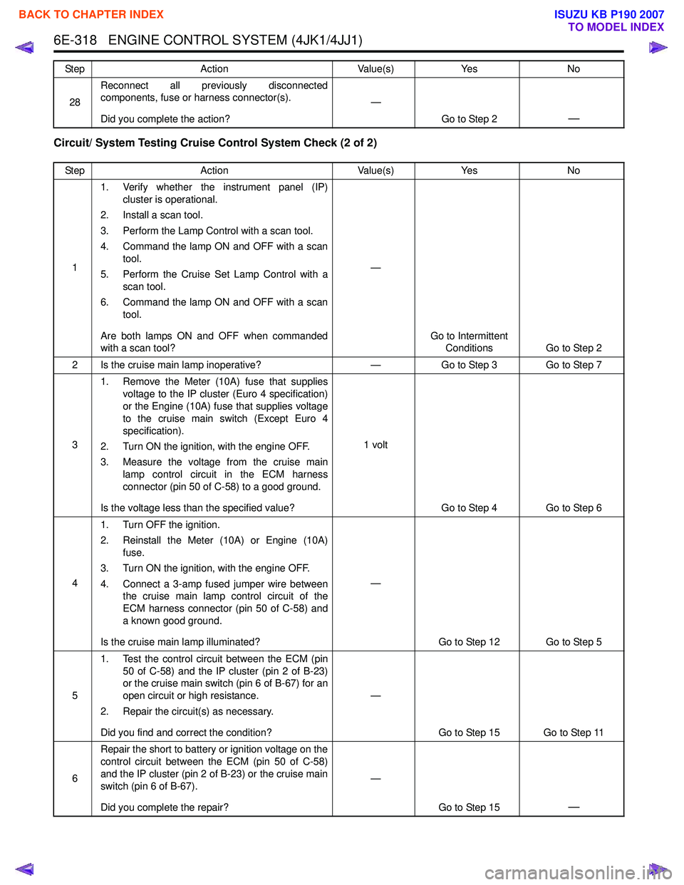
6E-318 ENGINE CONTROL SYSTEM (4JK1/4JJ1)
Circuit/ System Testing Cruise Control System Check (2 of 2)
28Reconnect all previously disconnected
components, fuse or harness connector(s).
Did you complete the action? —
Go to Step 2
—
Step Action Value(s)Yes No
1 1. Verify whether the instrument panel (IP)
cluster is operational.
2. Install a scan tool.
3. Perform the Lamp Control with a scan tool.
4. Command the lamp ON and OFF with a scan tool.
5. Perform the Cruise Set Lamp Control with a scan tool.
6. Command the lamp ON and OFF with a scan tool.
Are both lamps ON and OFF when commanded
with a scan tool? —
Go to Intermittent Conditions Go to Step 2
2 Is the cruise main lamp inoperative? —Go to Step 3 Go to Step 7
3 1. Remove the Meter (10A) fuse that supplies
voltage to the IP cluster (Euro 4 specification)
or the Engine (10A) fuse that supplies voltage
to the cruise main switch (Except Euro 4
specification).
2. Turn ON the ignition, with the engine OFF.
3. Measure the voltage from the cruise main lamp control circuit in the ECM harness
connector (pin 50 of C-58) to a good ground.
Is the voltage less than the specified value? 1 volt
Go to Step 4 Go to Step 6
4 1. Turn OFF the ignition.
2. Reinstall the Meter (10A) or Engine (10A) fuse.
3. Turn ON the ignition, with the engine OFF.
4. Connect a 3-amp fused jumper wire between the cruise main lamp control circuit of the
ECM harness connector (pin 50 of C-58) and
a known good ground.
Is the cruise main lamp illuminated? —
Go to Step 12 Go to Step 5
5 1. Test the control circuit between the ECM (pin
50 of C-58) and the IP cluster (pin 2 of B-23)
or the cruise main switch (pin 6 of B-67) for an
open circuit or high resistance.
2. Repair the circuit(s) as necessary.
Did you find and correct the condition? —
Go to Step 15 Go to Step 11
6 Repair the short to battery or ignition voltage on the
control circuit between the ECM (pin 50 of C-58)
and the IP cluster (pin 2 of B-23) or the cruise main
switch (pin 6 of B-67).
Did you complete the repair? —
Go to Step 15
—
Step Action Value(s)Yes No
BACK TO CHAPTER INDEX
TO MODEL INDEX
ISUZU KB P190 2007
Page 1936 of 6020
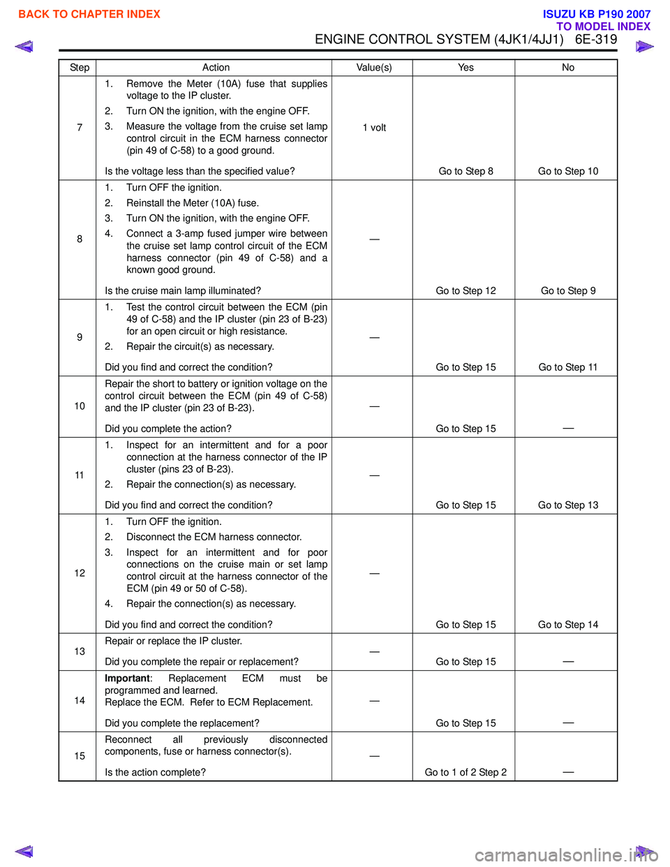
ENGINE CONTROL SYSTEM (4JK1/4JJ1) 6E-319
71. Remove the Meter (10A) fuse that supplies
voltage to the IP cluster.
2. Turn ON the ignition, with the engine OFF.
3. Measure the voltage from the cruise set lamp control circuit in the ECM harness connector
(pin 49 of C-58) to a good ground.
Is the voltage less than the specified value? 1 volt
Go to Step 8 Go to Step 10
8 1. Turn OFF the ignition.
2. Reinstall the Meter (10A) fuse.
3. Turn ON the ignition, with the engine OFF.
4. Connect a 3-amp fused jumper wire between the cruise set lamp control circuit of the ECM
harness connector (pin 49 of C-58) and a
known good ground.
Is the cruise main lamp illuminated? —
Go to Step 12 Go to Step 9
9 1. Test the control circuit between the ECM (pin
49 of C-58) and the IP cluster (pin 23 of B-23)
for an open circuit or high resistance.
2. Repair the circuit(s) as necessary.
Did you find and correct the condition? —
Go to Step 15 Go to Step 11
10 Repair the short to battery or ignition voltage on the
control circuit between the ECM (pin 49 of C-58)
and the IP cluster (pin 23 of B-23).
Did you complete the action? —
Go to Step 15
—
111. Inspect for an intermittent and for a poor
connection at the harness connector of the IP
cluster (pins 23 of B-23).
2. Repair the connection(s) as necessary.
Did you find and correct the condition? —
Go to Step 15 Go to Step 13
12 1. Turn OFF the ignition.
2. Disconnect the ECM harness connector.
3. Inspect for an intermittent and for poor connections on the cruise main or set lamp
control circuit at the harness connector of the
ECM (pin 49 or 50 of C-58).
4. Repair the connection(s) as necessary.
Did you find and correct the condition? —
Go to Step 15 Go to Step 14
13 Repair or replace the IP cluster.
Did you complete the repair or replacement? —
Go to Step 15
—
14Important
: Replacement ECM must be
programmed and learned.
Replace the ECM. Refer to ECM Replacement.
Did you complete the replacement? —
Go to Step 15
—
15Reconnect all previously disconnected
components, fuse or harness connector(s).
Is the action complete? —
Go to 1 of 2 Step 2
—
Step Action Value(s)Yes No
BACK TO CHAPTER INDEX
TO MODEL INDEX
ISUZU KB P190 2007
Page 1949 of 6020
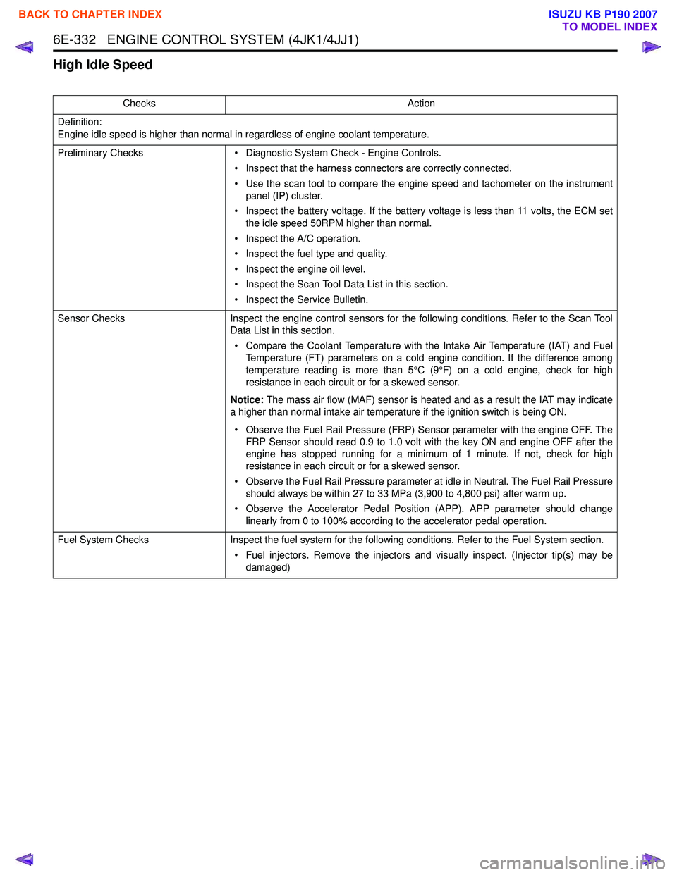
6E-332 ENGINE CONTROL SYSTEM (4JK1/4JJ1)
High Idle Speed
ChecksAction
Definition:
Engine idle speed is higher than normal in regardless of engine coolant temperature.
Preliminary Checks • Diagnostic System Check - Engine Controls.
• Inspect that the harness connectors are correctly connected.
• Use the scan tool to compare the engine speed and tachometer on the instrument panel (IP) cluster.
• Inspect the battery voltage. If the battery voltage is less than 11 volts, the ECM set the idle speed 50RPM higher than normal.
• Inspect the A/C operation.
• Inspect the fuel type and quality.
• Inspect the engine oil level.
• Inspect the Scan Tool Data List in this section.
• Inspect the Service Bulletin.
Sensor Checks Inspect the engine control sensors for the following conditions. Refer to the Scan Tool
Data List in this section.
• Compare the Coolant Temperature with the Intake Air Temperature (IAT) and Fuel Temperature (FT) parameters on a cold engine condition. If the difference among
temperature reading is more than 5 °C (9 °F) on a cold engine, check for high
resistance in each circuit or for a skewed sensor.
Notice: The mass air flow (MAF) sensor is heated and as a result the IAT may indicate
a higher than normal intake air temperature if the ignition switch is being ON.
• Observe the Fuel Rail Pressure (FRP) Sensor parameter with the engine OFF. The FRP Sensor should read 0.9 to 1.0 volt with the key ON and engine OFF after the
engine has stopped running for a minimum of 1 minute. If not, check for high
resistance in each circuit or for a skewed sensor.
• Observe the Fuel Rail Pressure parameter at idle in Neutral. The Fuel Rail Pressure should always be within 27 to 33 MPa (3,900 to 4,800 psi) after warm up.
• Observe the Accelerator Pedal Position (APP). APP parameter should change linearly from 0 to 100% according to the accelerator pedal operation.
Fuel System Checks Inspect the fuel system for the following conditions. Refer to the Fuel System section.
• Fuel injectors. Remove the injectors and visually inspect. (Injector tip(s) may be damaged)
BACK TO CHAPTER INDEX
TO MODEL INDEX
ISUZU KB P190 2007
Page 1965 of 6020
6E-348 ENGINE CONTROL SYSTEM (4JK1/4JJ1)
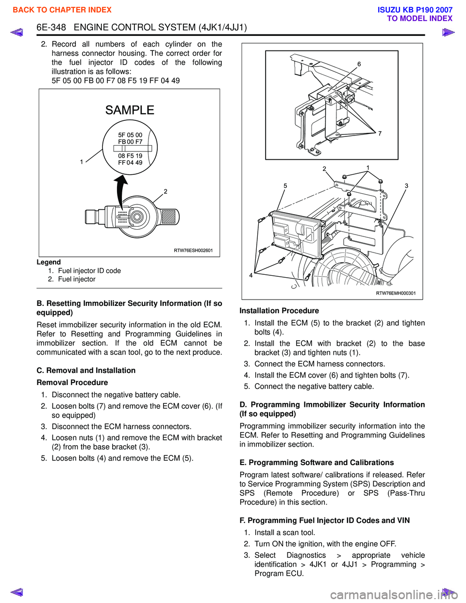
2. Record all numbers of each cylinder on theharness connector housing. The correct order for
the fuel injector ID codes of the following
illustration is as follows:
5F 05 00 FB 00 F7 08 F5 19 FF 04 49
Legend
1. Fuel injector ID code
2. Fuel injector
B. Resetting Immobilizer Security Information (If so
equipped)
Reset immobilizer security information in the old ECM.
Refer to Resetting and Programming Guidelines in
immobilizer section. If the old ECM cannot be
communicated with a scan tool, go to the next produce.
C. Removal and Installation
Removal Procedure 1. Disconnect the negative battery cable.
2. Loosen bolts (7) and remove the ECM cover (6). (If so equipped)
3. Disconnect the ECM harness connectors.
4. Loosen nuts (1) and remove the ECM with bracket (2) from the base bracket (3).
5. Loosen bolts (4) and remove the ECM (5). Installation Procedure
1. Install the ECM (5) to the bracket (2) and tighten bolts (4).
2. Install the ECM with bracket (2) to the base bracket (3) and tighten nuts (1).
3. Connect the ECM harness connectors.
4. Install the ECM cover (6) and tighten bolts (7).
5. Connect the negative battery cable.
D. Programming Immobilizer Security Information
(If so equipped)
Programming immobilizer security information into the
ECM. Refer to Resetting and Programming Guidelines
in immobilizer section.
E. Programming Software and Calibrations
Program latest software/ calibrations if released. Refer
to Service Programming System (SPS) Description and
SPS (Remote Procedure) or SPS (Pass-Thru
Procedure) in this section.
F. Programming Fuel Injector ID Codes and VIN 1. Install a scan tool.
2. Turn ON the ignition, with the engine OFF.
3. Select Diagnostics > appropriate vehicle identification > 4JK1 or 4JJ1 > Programming >
Program ECU.
RTW76ESH002601
5F 05 00
FB 00 F7
SAMPLE
08 F5 19
FF 0 4 49
2
1
RTW76EMH000301
5
1
2
3
4
6
7
BACK TO CHAPTER INDEX
TO MODEL INDEX
ISUZU KB P190 2007