Page 4269 of 6020

7A1-30 CONSTRUCTION AND FUNCTION
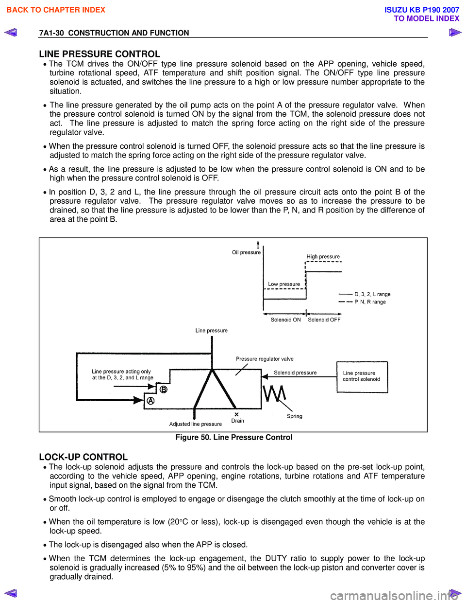
LINE PRESSURE CONTROL
• The TCM drives the ON/OFF type line pressure solenoid based on the APP opening, vehicle speed,
turbine rotational speed, ATF temperature and shift position signal. The ON/OFF type line pressure
solenoid is actuated, and switches the line pressure to a high or low pressure number appropriate to the
situation.
• The line pressure generated by the oil pump acts on the point A of the pressure regulator valve. When
the pressure control solenoid is turned ON by the signal from the TCM, the solenoid pressure does not
act. The line pressure is adjusted to match the spring force acting on the right side of the pressure
regulator valve.
• When the pressure control solenoid is turned OFF, the solenoid pressure acts so that the line pressure is
adjusted to match the spring force acting on the right side of the pressure regulator valve.
• As a result, the line pressure is adjusted to be low when the pressure control solenoid is ON and to be
high when the pressure control solenoid is OFF.
• In position D, 3, 2 and L, the line pressure through the oil pressure circuit acts onto the point B of the
pressure regulator valve. The pressure regulator valve moves so as to increase the pressure to be
drained, so that the line pressure is adjusted to be lower than the P, N, and R position by the difference of
area at the point B.
Figure 50. Line Pressure Control
LOCK-UP CONTROL
• The lock-up solenoid adjusts the pressure and controls the lock-up based on the pre-set lock-up point,
according to the vehicle speed, APP opening, engine rotations, turbine rotations and ATF temperature
input signal, based on the signal from the TCM.
• Smooth lock-up control is employed to engage or disengage the clutch smoothly at the time of lock-up on
or off.
• When the oil temperature is low (20°C or less), lock-up is disengaged even though the vehicle is at the
lock-up speed.
• The lock-up is disengaged also when the APP is closed.
• When the TCM determines the lock-up engagement, the DUTY ratio to supply power to the lock-up
solenoid is gradually increased (5% to 95%) and the oil between the lock-up piston and converter cover is
gradually drained.
BACK TO CHAPTER INDEX
TO MODEL INDEX
ISUZU KB P190 2007
Page 4270 of 6020

CONSTRUCTION AND FUNCTION 7A1-31
As a result, the lock-up piston is fitted slowly to the converter cover under pressure securing smooth lock-
up engagement.
Figure 51. Lock-up Control
DIRECT ELECTRIC SHIFT CONTROL (DESC)
Feature
• Based on each switch signal (low & reverse brake pressure, 2-4 brake pressure & high clutch pressure)
and each sensor signal (turbine sensor, speed sensor, engine speed signal & APP position signal), the
duty cycle type solenoid adjusts the clutch pressure to match the engine load and vehicle travel
conditions. Controlling the engagement and disengagement of the clutch and brake pressure is directly
and accurately controlled via TCM, which is different to the previous accumulator type.
Operation
• Instead of the previous system (on/off type of shift solenoid and shift valve), the combination of the duty
cycle type solenoid and the amplifier (Amp) valve are used to adjust the clutch pressure to match the
engine load and vehicle travel conditions, based on the signal from the TCM. Also, the pressure switch
provided in the oil passage of the control valve transmits the oil pressure condition (at that time) to TCM,
enabling the engagement and disengagement control of the clutch and brake to be directly and finely
carried out.
• When the gear is shifted from the 2nd to 3rd, 3rd to 4th (O/D), 4th (O/D) to 3rd and 3rd to 2nd, the clutch
pressures on the engagement side and disengagement side are simultaneously controlled.
As a result, engine racing or clutch drag is prevented which enables a smooth and quick shift response.
BACK TO CHAPTER INDEX
TO MODEL INDEX
ISUZU KB P190 2007
Page 4272 of 6020

CONSTRUCTION AND FUNCTION 7A1-33
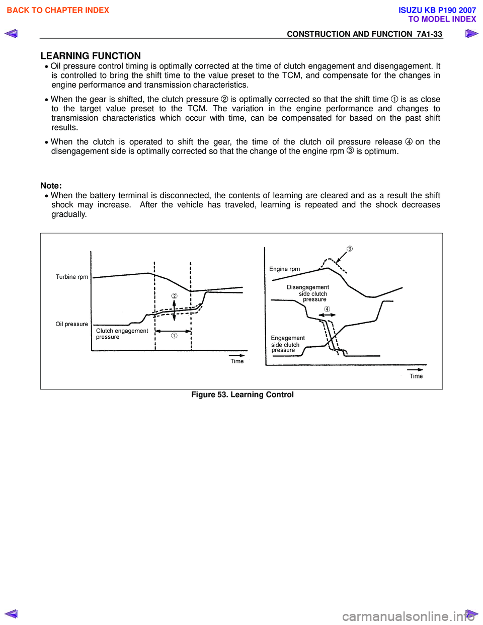
LEARNING FUNCTION
• Oil pressure control timing is optimally corrected at the time of clutch engagement and disengagement. It
is controlled to bring the shift time to the value preset to the TCM, and compensate for the changes in
engine performance and transmission characteristics.
• When the gear is shifted, the clutch pressure 2 is optimally corrected so that the shift time 1 is as close
to the target value preset to the TCM. The variation in the engine performance and changes to
transmission characteristics which occur with time, can be compensated for based on the past shift
results.
• When the clutch is operated to shift the gear, the time of the clutch oil pressure release 4 on the
disengagement side is optimally corrected so that the change of the engine rpm
3 is optimum.
Note:
• When the battery terminal is disconnected, the contents of learning are cleared and as a result the shift
shock may increase. After the vehicle has traveled, learning is repeated and the shock decreases
gradually.
Figure 53. Learning Control
BACK TO CHAPTER INDEX
TO MODEL INDEX
ISUZU KB P190 2007
Page 4273 of 6020

7A1-34 CONSTRUCTION AND FUNCTION
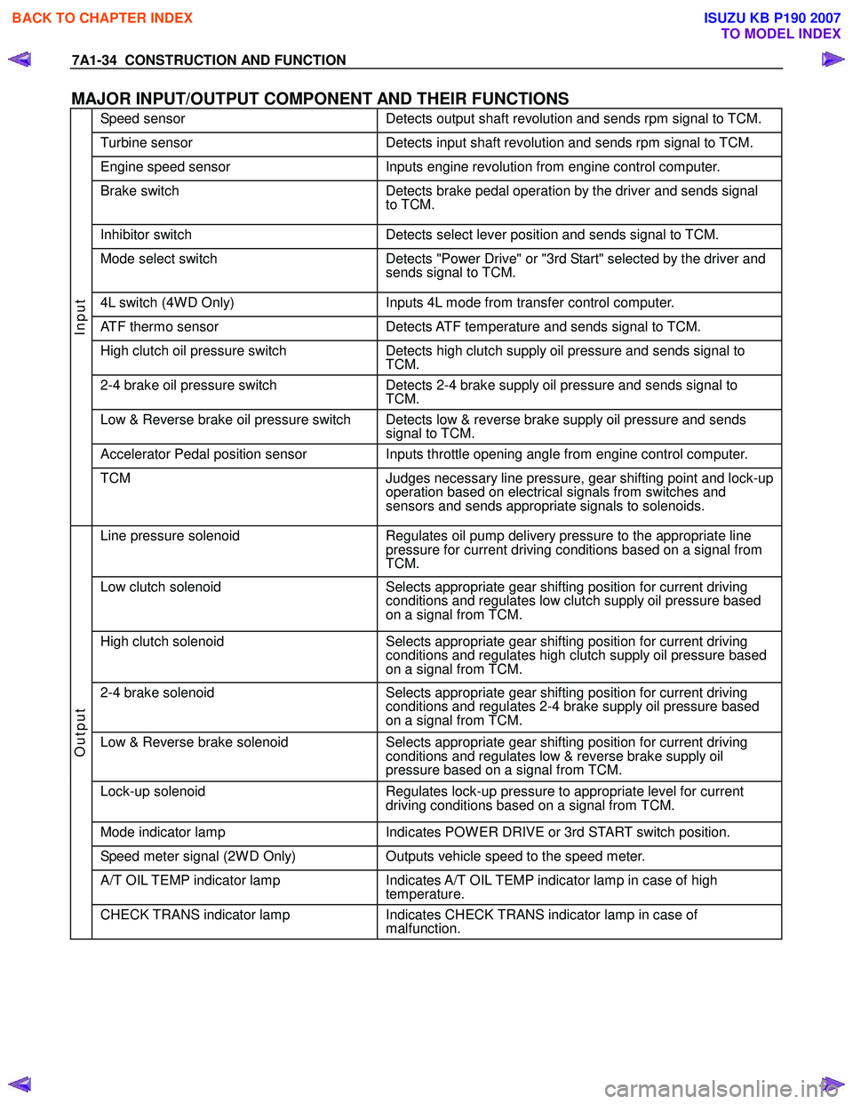
MAJOR INPUT/OUTPUT COMPONENT AND THEIR FUNCTIONS
Speed sensor Detects output shaft revolution and sends rpm signal to TCM.
Turbine sensor Detects input shaft revolution and sends rpm signal to TCM.
Engine speed sensor Inputs engine revolution from engine control computer.
Brake switch Detects brake pedal operation by the driver and sends signal
to TCM.
Inhibitor switch Detects select lever position and sends signal to TCM.
Mode select switch Detects "Power Drive" or "3rd Start" selected by the driver and
sends signal to TCM.
4L switch (4W D Only) Inputs 4L mode from transfer control computer.
ATF thermo sensor Detects ATF temperature and sends signal to TCM.
High clutch oil pressure switch Detects high clutch supply oil pressure and sends signal to
TCM.
2-4 brake oil pressure switch Detects 2-4 brake supply oil pressure and sends signal to
TCM.
Low & Reverse brake oil pressure switch Detects low & reverse brake supply oil pressure and sends signal to TCM.
Accelerator Pedal position sensor Inputs throttle opening angle from engine control computer.
Input
TCM Judges necessary line pressure, gear shifting point and lock-up
operation based on electrical signals from switches and
sensors and sends appropriate signals to solenoids.
Line pressure solenoid Regulates oil pump delivery pressure to the appropriate line
pressure for current driving conditions based on a signal from
TCM.
Low clutch solenoid Selects appropriate gear shifting position for current driving
conditions and regulates low clutch supply oil pressure based
on a signal from TCM.
High clutch solenoid Selects appropriate gear shifting position for current driving
conditions and regulates high clutch supply oil pressure based
on a signal from TCM.
2-4 brake solenoid Selects appropriate gear shifting position for current driving
conditions and regulates 2-4 brake supply oil pressure based
on a signal from TCM.
Low & Reverse brake solenoid Selects appropriate gear shifting position for current driving
conditions and regulates low & reverse brake supply oil
pressure based on a signal from TCM.
Lock-up solenoid Regulates lock-up pressure to appropriate level for current
driving conditions based on a signal from TCM.
Mode indicator lamp Indicates POW ER DRIVE or 3rd START switch position.
Speed meter signal (2W D Only) Outputs vehicle speed to the speed meter.
A/T OIL TEMP indicator lamp Indicates A/T OIL TEMP indicator lamp in case of high
temperature.
Output
CHECK TRANS indicator lamp Indicates CHECK TRANS indicator lamp in case of
malfunction.
BACK TO CHAPTER INDEX
TO MODEL INDEX
ISUZU KB P190 2007
Page 4274 of 6020
CONSTRUCTION AND FUNCTION 7A1-35
CONTROL CIRCUIT BLOCK DIAGRAM
Speed sensor
Turbine sensor
Brake switch
Inhibitor switch
Power drive, 3rd start
switch
ATF oil thermo sensor
High clutch oil pressure
switch
2-4 brake oil pressure
switch
Low & reverse brake oil
pressure switch
Transfer control module
(4W D Only)
Engine Control Module
(ECM)
Line pressure solenoid
Low clutch solenoid
High clutch solenoid
2-4 brake solenoid
Low & reverse brake
solenoid
Lock-up solenoid
ATF temperature
indicator lamp
Speed meter (2W D
Only)
Power, 3rd start indicator
lamp
Check trans indicator
lamp
Data link connector Self-diagnosis
function
Transmission
Control
Module (TCM)
4L mode
Tachometer
signal output
APP PW M
position signal
output
Figure 54. Control Circuit Block Diagram
BACK TO CHAPTER INDEX
TO MODEL INDEX
ISUZU KB P190 2007
Page 4276 of 6020
CONSTRUCTION AND FUNCTION 7A1-37
COMPONENT AND THEIR OPERATING CONDITION
Clutch Brake Solenoid Pressure Switch
Select
lever
position
Gear
position
Gear Shift
Lock- up
L/C
H/C
R/C
L/O.C
L&R/B
2-4/B
L/C.S
H/C.S
L&R/ B.S
2-4/
B.S
L/U.S H/
C.P/ SW L&R/
B.P/SW 2-4
B.P/ SW
P - -
R Reverse -
N - -
1st
2nd
3rd
D
4th
1st
2nd
3rd
3
4th(*1)
1st
2nd
3rd(*1)
2
4th(*1)
1st
2nd(*1)
3rd(*1)
L
4th(*1)
*1: Shifting the select lever to manual position at high speed, the transmission may hold the gear position
until vehicle speed get down to certain speed to prevent engine overrun.
- Engaged or operated
- Operative when accelerating
BACK TO CHAPTER INDEX
TO MODEL INDEX
ISUZU KB P190 2007
Page 4280 of 6020

CONSTRUCTION AND FUNCTION 7A1-41
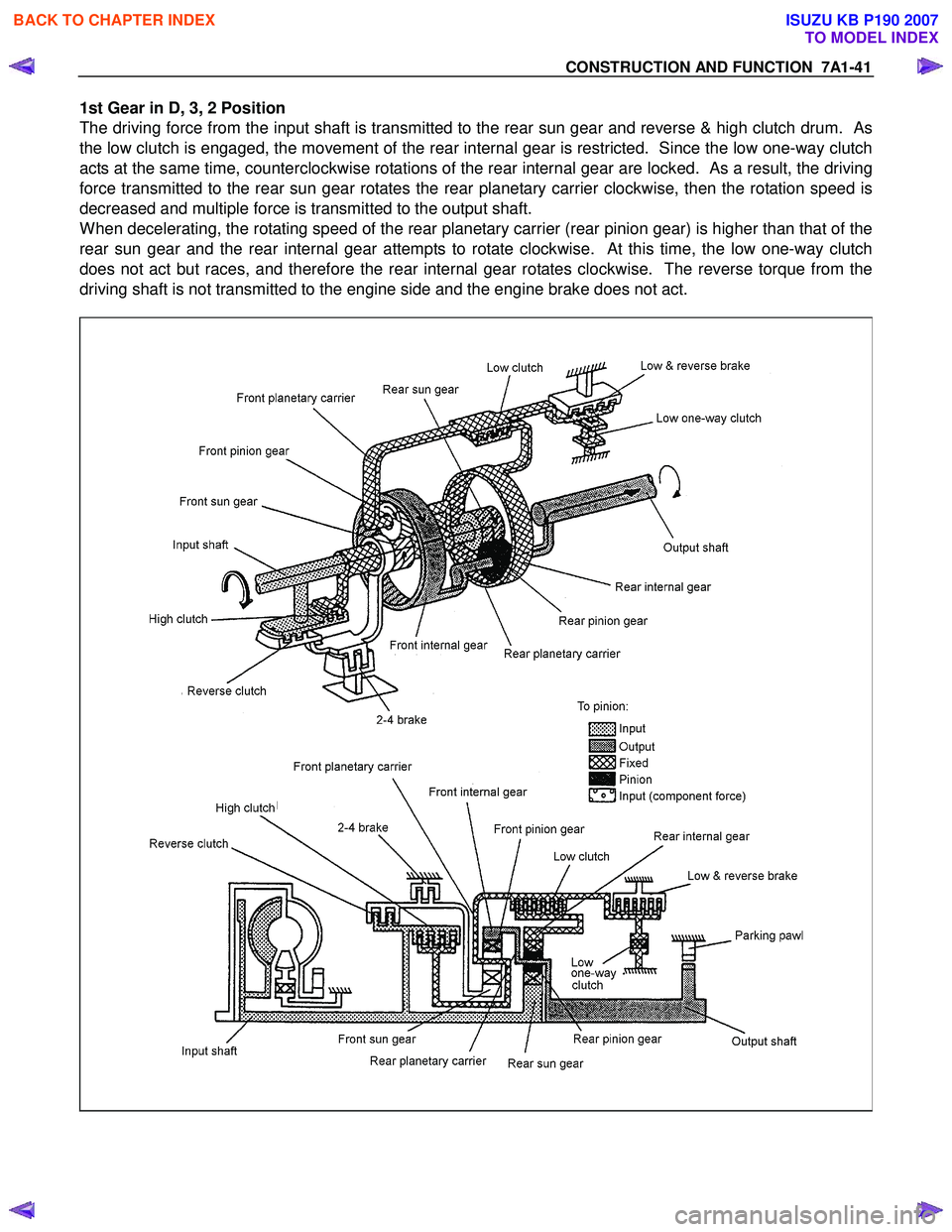
1st Gear in D, 3, 2 Position
The driving force from the input shaft is transmitted to the rear sun gear and reverse & high clutch drum. As
the low clutch is engaged, the movement of the rear internal gear is restricted. Since the low one-way clutch
acts at the same time, counterclockwise rotations of the rear internal gear are locked. As a result, the driving
force transmitted to the rear sun gear rotates the rear planetary carrier clockwise, then the rotation speed is
decreased and multiple force is transmitted to the output shaft.
When decelerating, the rotating speed of the rear planetary carrier (rear pinion gear) is higher than that of the
rear sun gear and the rear internal gear attempts to rotate clockwise. At this time, the low one-way clutch
does not act but races, and therefore the rear internal gear rotates clockwise. The reverse torque from the
driving shaft is not transmitted to the engine side and the engine brake does not act.
BACK TO CHAPTER INDEX
TO MODEL INDEX
ISUZU KB P190 2007
Page 4281 of 6020
7A1-42 CONSTRUCTION AND FUNCTION
1st Gear in L Position
The basic mechanism is the same as in the D, 3, and 2 positions. To apply the engine brake, the low &
reverse brake is engaged to restrict the movement of the low one-way clutch.
When decelerating, as the rear internal gear is fixed, reverse torque from the drive shaft is transmitted to the
engine side so that the engine brake is applied.
BACK TO CHAPTER INDEX
TO MODEL INDEX
ISUZU KB P190 2007