2007 ISUZU KB P190 turn signal
[x] Cancel search: turn signalPage 4269 of 6020
7A1-30 CONSTRUCTION AND FUNCTION
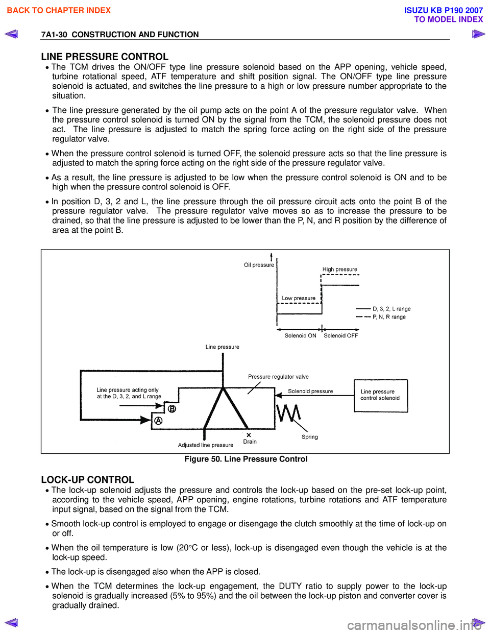
LINE PRESSURE CONTROL
• The TCM drives the ON/OFF type line pressure solenoid based on the APP opening, vehicle speed,
turbine rotational speed, ATF temperature and shift position signal. The ON/OFF type line pressure
solenoid is actuated, and switches the line pressure to a high or low pressure number appropriate to the
situation.
• The line pressure generated by the oil pump acts on the point A of the pressure regulator valve. When
the pressure control solenoid is turned ON by the signal from the TCM, the solenoid pressure does not
act. The line pressure is adjusted to match the spring force acting on the right side of the pressure
regulator valve.
• When the pressure control solenoid is turned OFF, the solenoid pressure acts so that the line pressure is
adjusted to match the spring force acting on the right side of the pressure regulator valve.
• As a result, the line pressure is adjusted to be low when the pressure control solenoid is ON and to be
high when the pressure control solenoid is OFF.
• In position D, 3, 2 and L, the line pressure through the oil pressure circuit acts onto the point B of the
pressure regulator valve. The pressure regulator valve moves so as to increase the pressure to be
drained, so that the line pressure is adjusted to be lower than the P, N, and R position by the difference of
area at the point B.
Figure 50. Line Pressure Control
LOCK-UP CONTROL
• The lock-up solenoid adjusts the pressure and controls the lock-up based on the pre-set lock-up point,
according to the vehicle speed, APP opening, engine rotations, turbine rotations and ATF temperature
input signal, based on the signal from the TCM.
• Smooth lock-up control is employed to engage or disengage the clutch smoothly at the time of lock-up on
or off.
• When the oil temperature is low (20°C or less), lock-up is disengaged even though the vehicle is at the
lock-up speed.
• The lock-up is disengaged also when the APP is closed.
• When the TCM determines the lock-up engagement, the DUTY ratio to supply power to the lock-up
solenoid is gradually increased (5% to 95%) and the oil between the lock-up piston and converter cover is
gradually drained.
BACK TO CHAPTER INDEX
TO MODEL INDEX
ISUZU KB P190 2007
Page 4289 of 6020
TRANSMISSION CONTROL SYSTEM (JR405E) 7A2-5
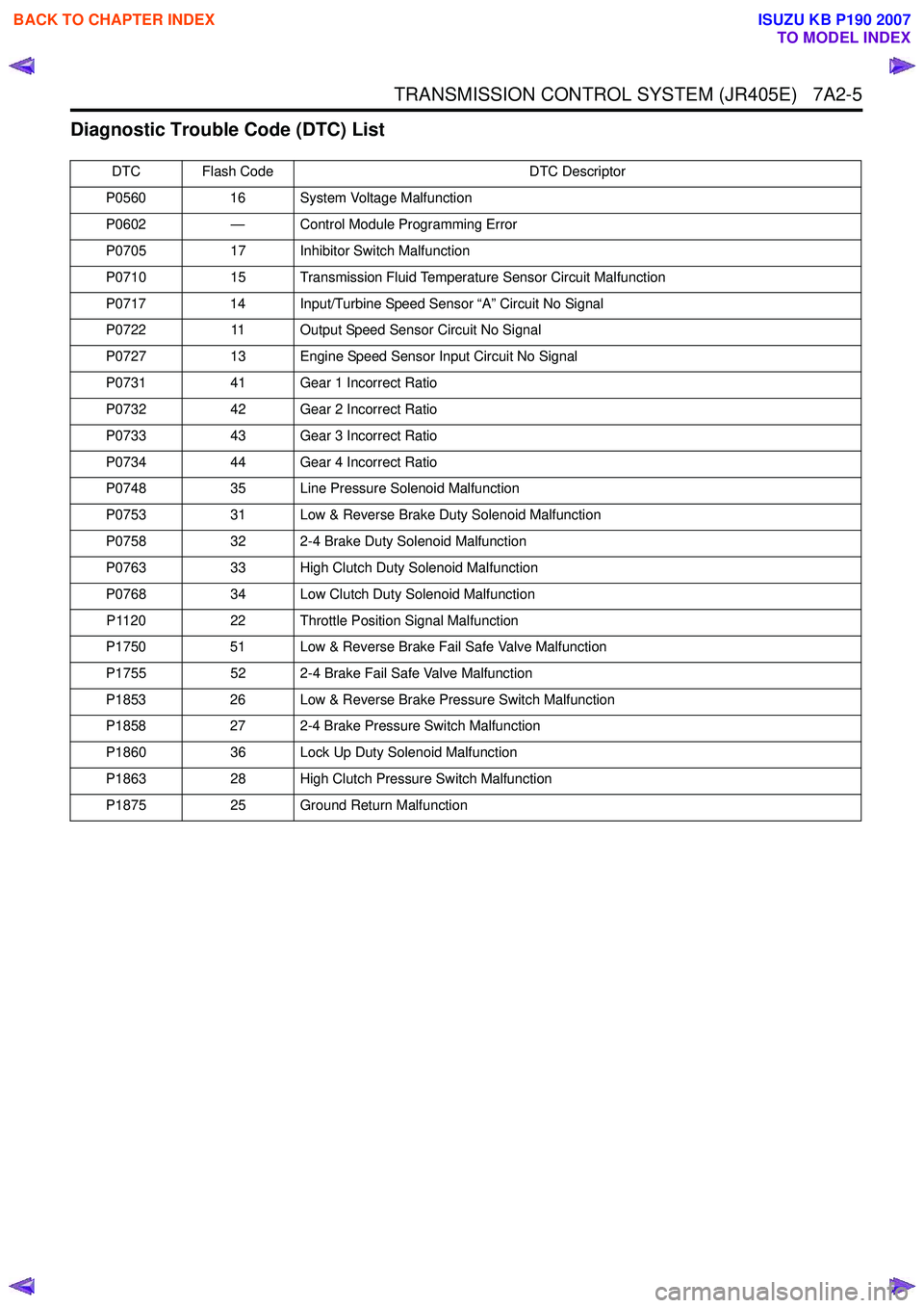
Diagnostic Trouble Code (DTC) List
DTC Flash CodeDTC Descriptor
P0560 16 System Voltage Malfunction
P0602 — Control Module Programming Error
P0705 17 Inhibitor Switch Malfunction
P0710 15 Transmission Fluid Temperature Sensor Circuit Malfunction
P0717 14 Input/Turbine Speed Sensor “A” Circuit No Signal
P0722 11 Output Speed Sensor Circuit No Signal
P0727 13 Engine Speed Sensor Input Circuit No Signal
P0731 41 Gear 1 Incorrect Ratio
P0732 42 Gear 2 Incorrect Ratio
P0733 43 Gear 3 Incorrect Ratio
P0734 44 Gear 4 Incorrect Ratio
P0748 35 Line Pressure Solenoid Malfunction
P0753 31 Low & Reverse Brake Duty Solenoid Malfunction
P0758 32 2-4 Brake Duty Solenoid Malfunction
P0763 33 High Clutch Duty Solenoid Malfunction
P0768 34 Low Clutch Duty Solenoid Malfunction
P1120 22 Throttle Position Signal Malfunction
P1750 51 Low & Reverse Brake Fail Safe Valve Malfunction
P1755 52 2-4 Brake Fail Safe Valve Malfunction
P1853 26 Low & Reverse Brake Pressure Switch Malfunction
P1858 27 2-4 Brake Pressure Switch Malfunction
P1860 36 Lock Up Duty Solenoid Malfunction
P1863 28 High Clutch Pressure Switch Malfunction
P1875 25 Ground Return Malfunction
BACK TO CHAPTER INDEX
TO MODEL INDEX
ISUZU KB P190 2007
Page 4302 of 6020
7A2-18 TRANSMISSION CONTROL SYSTEM (JR405E)
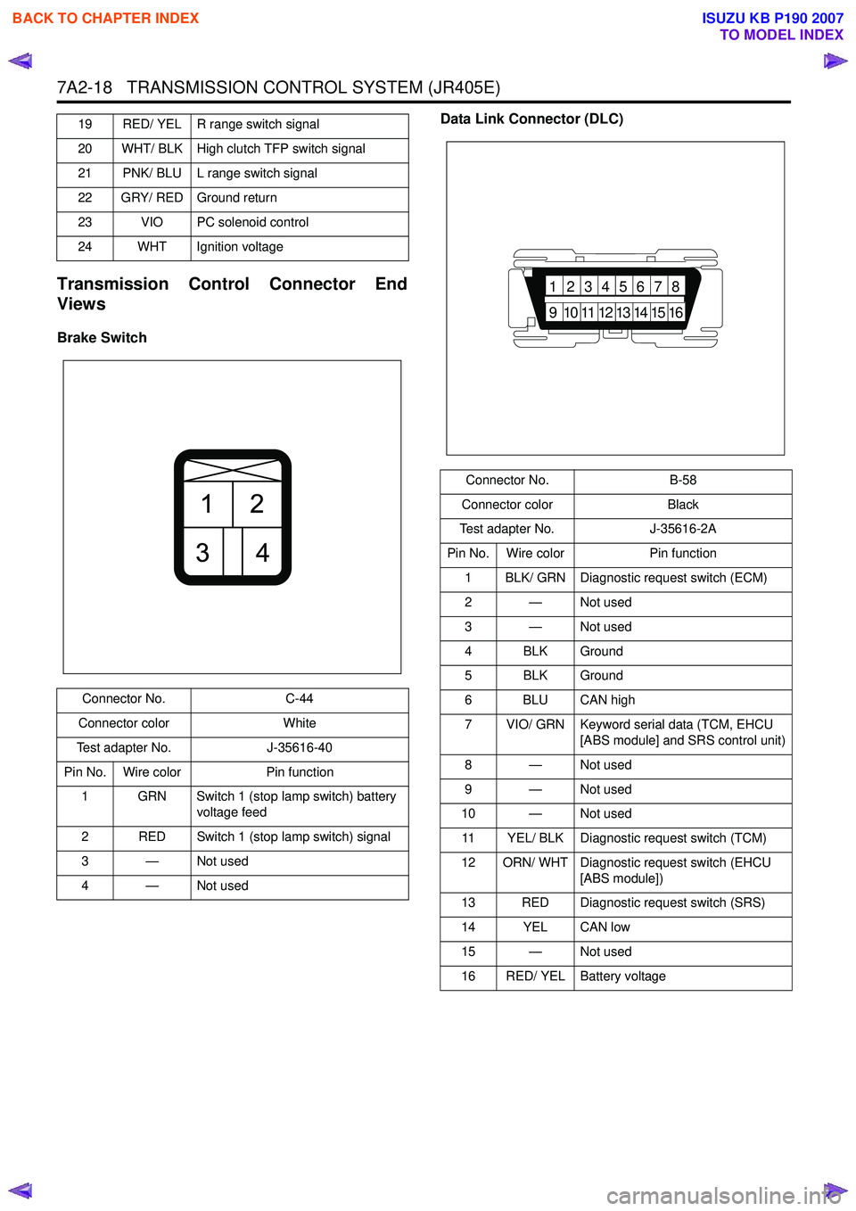
Transmission Control Connector End
Views
Brake Switch Data Link Connector (DLC)
19 RED/ YEL R range switch signal
20 WHT/ BLK High clutch TFP switch signal
21 PNK/ BLU L range switch signal
22 GRY/ RED Ground return
23 VIO PC solenoid control
24 WHT Ignition voltage
Connector No. C-44
Connector color White
Test adapter No. J-35616-40
Pin No. Wire color Pin function
1 GRN Switch 1 (stop lamp switch) battery voltage feed
2 RED Switch 1 (stop lamp switch) signal
3—Not used
4—Not used
21
34
Connector No. B-58
Connector color Black
Test adapter No. J-35616-2A
Pin No. Wire color Pin function
1 BLK/ GRN Diagnostic request switch (ECM)
2 — Not used
3 — Not used
4 BLK Ground
5 BLK Ground
6 BLU CAN high
7 VIO/ GRN Keyword serial data (TCM, EHCU [ABS module] and SRS control unit)
8 — Not used
9 — Not used
10 — Not used
11 YEL/ BLK Diagnostic request switch (TCM)
12 ORN/ WHT Diagnostic request switch (EHCU [ABS module])
13 RED Diagnostic request switch (SRS)
14 YEL CAN low
15 — Not used
16 RED/ YEL Battery voltage
87654321
16151413121110
9
BACK TO CHAPTER INDEX
TO MODEL INDEX
ISUZU KB P190 2007
Page 4304 of 6020
7A2-20 TRANSMISSION CONTROL SYSTEM (JR405E)
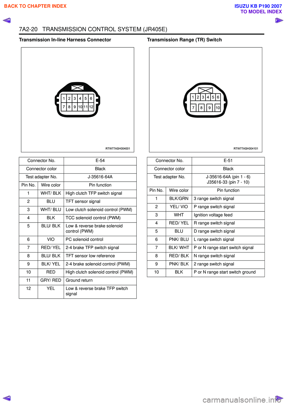
Transmission In-line Harness ConnectorTransmission Range (TR) Switch
Connector No.E-54
Connector color Black
Test adapter No. J-35616-64A
Pin No. Wire color Pin function
1 WHT/ BLK High clutch TFP switch signal
2 BLU TFT sensor signal
3 WHT/ BLU Low clutch solenoid control (PWM)
4 BLK TCC solenoid control (PWM)
5 BLU/ BLK Low & reverse brake solenoid control (PWM)
6 VIO PC solenoid control
7 RED/ YEL 2-4 brake TFP switch signal
8 BLU/ BLK TFT sensor low reference
9 BLK/ YEL 2-4 brake solenoid control (PWM)
10 RED High clutch solenoid control (PWM)
11 GRY/ RED Ground return
12 YEL Low & reverse brake TFP switch signal
RTW77ASH004001
123456
789101112
Connector No. E-51
Connector color Black
Test adapter No. J-35616-64A (pin 1 - 6) J35616-33 (pin 7 - 10)
Pin No. Wire color Pin function
1 BLK/GRN 3 range switch signal
2 YEL/ VIO P range switch signal
3 WHT Ignition voltage feed
4 RED/ YEL R range switch signal
5 BLU D range switch signal
6 PNK/ BLU L range switch signal
7 BLK/ WHT P or N range start switch signal
8 RED/ BLK N range switch signal
9 PNK/ BLK 2 range switch signal
10 BLK P or N range start switch ground
RTW77ASH004101
123456
78910
BACK TO CHAPTER INDEX
TO MODEL INDEX
ISUZU KB P190 2007
Page 4312 of 6020
7A2-28 TRANSMISSION CONTROL SYSTEM (JR405E)
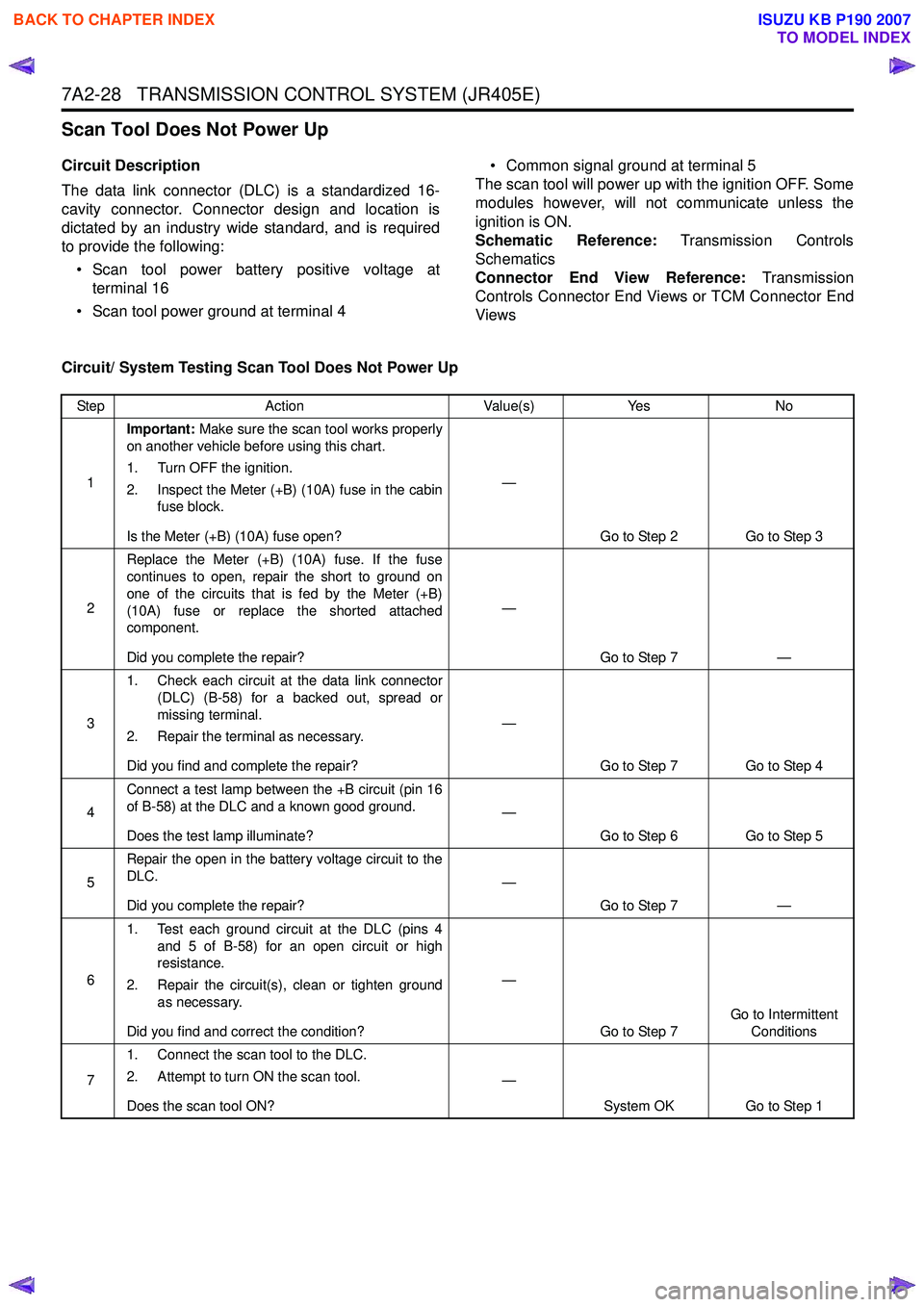
Scan Tool Does Not Power Up
Circuit Description
The data link connector (DLC) is a standardized 16-
cavity connector. Connector design and location is
dictated by an industry wide standard, and is required
to provide the following:
• Scan tool power battery positive voltage at terminal 16
• Scan tool power ground at terminal 4 • Common signal ground at terminal 5
The scan tool will power up with the ignition OFF. Some
modules however, will not communicate unless the
ignition is ON.
Schematic Reference: Transmission Controls
Schematics
Connector End View Reference: Transmission
Controls Connector End Views or TCM Connector End
Views
Circuit/ System Testing Scan Tool Does Not Power Up
Step Action Value(s)Yes No
1 Important:
Make sure the scan tool works properly
on another vehicle before using this chart.
1. Turn OFF the ignition.
2. Inspect the Meter (+B) (10A) fuse in the cabin fuse block.
Is the Meter (+B) (10A) fuse open? —
Go to Step 2 Go to Step 3
2 Replace the Meter (+B) (10A) fuse. If the fuse
continues to open, repair the short to ground on
one of the circuits that is fed by the Meter (+B)
(10A) fuse or replace the shorted attached
component.
Did you complete the repair? —
Go to Step 7 —
3 1. Check each circuit at the data link connector
(DLC) (B-58) for a backed out, spread or
missing terminal.
2. Repair the terminal as necessary.
Did you find and complete the repair? —
Go to Step 7 Go to Step 4
4 Connect a test lamp between the +B circuit (pin 16
of B-58) at the DLC and a known good ground.
Does the test lamp illuminate? —
Go to Step 6 Go to Step 5
5 Repair the open in the battery voltage circuit to the
DLC.
Did you complete the repair? —
Go to Step 7 —
6 1. Test each ground circuit at the DLC (pins 4
and 5 of B-58) for an open circuit or high
resistance.
2. Repair the circuit(s), clean or tighten ground as necessary.
Did you find and correct the condition? —
Go to Step 7 Go to Intermittent
Conditions
7 1. Connect the scan tool to the DLC.
2. Attempt to turn ON the scan tool.
Does the scan tool ON? —
System OK Go to Step 1
BACK TO CHAPTER INDEX
TO MODEL INDEX
ISUZU KB P190 2007
Page 4320 of 6020

7A2-36 TRANSMISSION CONTROL SYSTEM (JR405E)
DTC P0705 (Flash Code 17)
Circuit Description
The transmission range (TR) switch is connected to the
transmission manual shaft and installed externally to
the transmission case. The TR switch relays a signal to
the TCM indicating transmission range position by
detecting ignition voltage through an internal switch.
Only one of the seven internal switches will close for
each P, R, N, D, 3, 2 and L position. Normally, the TCM
expects to detect one high voltage input for each
position. If the TCM detects more than one high voltage
input at the same time or no input, this DTC will set.
Condition for Running the DTC • The ignition switch is ON.
Condition for Setting the DTC
Either of following condition is met: • The TCM detects that the TR switch signals are all OFF for 2 seconds when the engine speed is more
than 500 RPM.
• The TCM detects that multiple TR switch signals for 1 second.
Action Taken When the DTC Sets • The TCM blinks the Check Trans lamp when the diagnostic runs and fails. During the vehicle running;
• The TCM holds the last gear position when the diagnostic runs and fails.
• The TCM inhibits lock up control.
After the vehicle stopped;
• The TCM stops all shift solenoid valves and fixes to the 3rd gear. If a fail-safe valve problem is
detected, the shift solenoid valves are not stopped
but gear is fixed to the 3rd gear.
• The TCM stops PC solenoid valve.
Condition for Clearing the DTC • The TCM turns OFF the Check Trans lamp when the diagnostic runs and does not fail.
• A current DTC clears when the diagnostic runs and does not fail.
Diagnostic Aids • If an intermittent condition is suspected, refer to Intermittent Conditions in this section.
Schematic Reference: Transmission Controls
Schematics
Connector End View Reference: Transmission
Controls Connector End Views or TCM Connector End
Views
Circuit/ System Testing DTC P0705
Step Action Value(s)Yes No
1 Did you perform the Diagnostic System Check -
Transmission Controls? —
Go to Step 2 Go to Diagnostic
System Check - Transmission Controls
2 1. Install a scan tool.
2. Turn ON the ignition, with the engine OFF.
3. Observe the Transmission Range (TR) Switch P, R, N, D, 3, 2 and L parameter with a scan
tool while selecting each transmission range.
Does the scan tool indicate ON when its position
and OFF when other positions? —
Go to Diagnostic Aids Go to Step 3
3 1. Check to ensure the TR switch is adjusted
correctly.
2. Adjust the TR switch as necessary. Refer to repair instructions (On-Vehicle Service).
Did you find and correct the condition? —
Go to Step 16 Go to Step 4
4 1. Turn OFF the ignition.
2. Disconnect the TR switch harness connector.
3. Turn ON the ignition, with the engine OFF.
Does the scan tool indicate all TR Switch
parameters OFF? —
Go to Step 5 Go to Step 11
BACK TO CHAPTER INDEX
TO MODEL INDEX
ISUZU KB P190 2007
Page 4322 of 6020
7A2-38 TRANSMISSION CONTROL SYSTEM (JR405E)
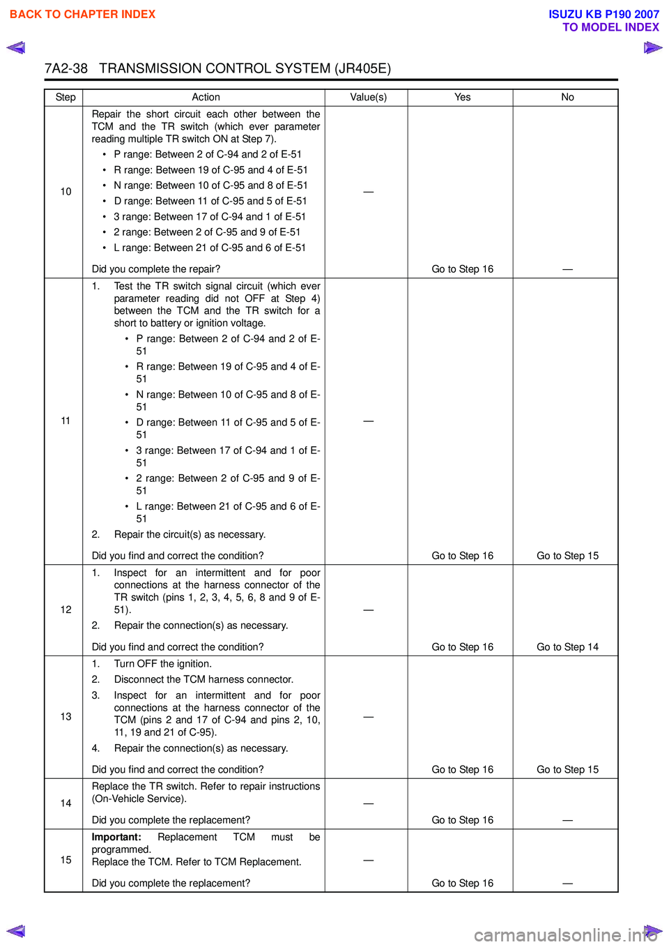
10Repair the short circuit each other between the
TCM and the TR switch (which ever parameter
reading multiple TR switch ON at Step 7).
• P range: Between 2 of C-94 and 2 of E-51
• R range: Between 19 of C-95 and 4 of E-51
• N range: Between 10 of C-95 and 8 of E-51
• D range: Between 11 of C-95 and 5 of E-51
• 3 range: Between 17 of C-94 and 1 of E-51
• 2 range: Between 2 of C-95 and 9 of E-51
• L range: Between 21 of C-95 and 6 of E-51
Did you complete the repair? —
Go to Step 16 —
11 1. Test the TR switch signal circuit (which ever
parameter reading did not OFF at Step 4)
between the TCM and the TR switch for a
short to battery or ignition voltage.
• P range: Between 2 of C-94 and 2 of E- 51
• R range: Between 19 of C-95 and 4 of E- 51
• N range: Between 10 of C-95 and 8 of E- 51
• D range: Between 11 of C-95 and 5 of E- 51
• 3 range: Between 17 of C-94 and 1 of E- 51
• 2 range: Between 2 of C-95 and 9 of E- 51
• L range: Between 21 of C-95 and 6 of E- 51
2. Repair the circuit(s) as necessary.
Did you find and correct the condition? —
Go to Step 16 Go to Step 15
12 1. Inspect for an intermittent and for poor
connections at the harness connector of the
TR switch (pins 1, 2, 3, 4, 5, 6, 8 and 9 of E-
51).
2. Repair the connection(s) as necessary.
Did you find and correct the condition? —
Go to Step 16 Go to Step 14
13 1. Turn OFF the ignition.
2. Disconnect the TCM harness connector.
3. Inspect for an intermittent and for poor connections at the harness connector of the
TCM (pins 2 and 17 of C-94 and pins 2, 10,
11, 19 and 21 of C-95).
4. Repair the connection(s) as necessary.
Did you find and correct the condition? —
Go to Step 16 Go to Step 15
14 Replace the TR switch. Refer to repair instructions
(On-Vehicle Service).
Did you complete the replacement? —
Go to Step 16 —
15 Important:
Replacement TCM must be
programmed.
Replace the TCM. Refer to TCM Replacement.
Did you complete the replacement? —
Go to Step 16 —
Step
Action Value(s)Yes No
BACK TO CHAPTER INDEX
TO MODEL INDEX
ISUZU KB P190 2007
Page 4324 of 6020
7A2-40 TRANSMISSION CONTROL SYSTEM (JR405E)
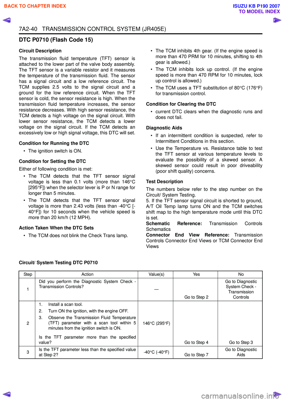
DTC P0710 (Flash Code 15)
Circuit Description
The transmission fluid temperature (TFT) sensor is
attached to the lower part of the valve body assembly.
The TFT sensor is a variable resistor and it measures
the temperature of the transmission fluid. The sensor
has a signal circuit and a low reference circuit. The
TCM supplies 2.5 volts to the signal circuit and a
ground for the low reference circuit. When the TFT
sensor is cold, the sensor resistance is high. When the
transmission fluid temperature increases, the sensor
resistance decreases. With high sensor resistance, the
TCM detects a high voltage on the signal circuit. With
lower sensor resistance, the TCM detects a lower
voltage on the signal circuit. If the TCM detects an
excessively low or high signal voltage, this DTC will set.
Condition for Running the DTC • The ignition switch is ON.
Condition for Setting the DTC
Either of following condition is met: • The TCM detects that the TFT sensor signal voltage is less than 0.1 volts (more than 146 °C
[295 °F]) when the selector lever is P or N range for
longer than 5 minutes.
• The TCM detects that the TFT sensor signal voltage is more than 2.43 volts (less than -40 °C [-
40 °F]) for 10 seconds when the vehicle speed is
more than 20 km/h (12 MPH).
Action Taken When the DTC Sets • The TCM does not blink the Check Trans lamp. • The TCM inhibits 4th gear. (If the engine speed is
more than 470 PRM for 10 minutes, shifting to 4th
gear is allowed.)
• The TCM inhibits lock up control. (If the engine speed is more than 470 RPM for 10 minutes, lock
up control is allowed.)
• The TCM uses a TFT substitution of 80 °C (176 °F)
for transmission control.
Condition for Clearing the DTC • current DTC clears when the diagnostic runs and does not fail.
Diagnostic Aids • If an intermittent condition is suspected, refer to Intermittent Conditions in this section.
• Use the Temperature vs. Resistance table to test the TFT sensor at various temperature levels to
evaluate the possibility of a skewed sensor. A
skewed sensor could result in poor driveability
(poor shift quality) concerns.
Test Description
The numbers below refer to the step number on the
Circuit/ System Testing.
5. If the TFT sensor signal circuit is shorted to ground,
A/T Oil Temp lamp turns ON and the TCM switches
shift map to the high temperature mode until this DTC
is set.
Schematic Reference: Transmission Controls
Schematics
Connector End View Reference: Transmission
Controls Connector End Views or TCM Connector End
Views
Circuit/ System Testing DTC P0710
Step Action Value(s)Yes No
1 Did you perform the Diagnostic System Check -
Transmission Controls? —
Go to Step 2 Go to Diagnostic
System Check -
Transmission Controls
2 1. Install a scan tool.
2. Turn ON the ignition, with the engine OFF.
3. Observe the Transmission Fluid Temperature (TFT) parameter with a scan tool within 5
minutes from the ignition switch is ON.
Is the TFT parameter more than the specified
value? 146
°C (295 °F)
Go to Step 4 Go to Step 3
3 Is the TFT parameter less than the specified value
at Step 2? -40
°C (-40 °F)
Go to Step 7 Go to Diagnostic
Aids
BACK TO CHAPTER INDEX
TO MODEL INDEX
ISUZU KB P190 2007