2007 ISUZU KB P190 turn signal
[x] Cancel search: turn signalPage 4079 of 6020
TRANSMISSION CONTROL SYSTEM (AW30–40LE) 7A2-113
(2) All of the following conditions are met.
• Device Control is not operating.
• Disable Normal Communication is receiving
enable.
• DTC Clear is not operating.
The following condition at ignition “OFF” form “ON” is
detected seven times in total in 1 cycle.
• Receiving BUS “OFF” information from CAN
controller.
Action Taken When The DTC Set
• Throttle judgment on torque reduction control, line
pressure control at stationary status, line pressure
reduction control at gear change and line pressure
reduction control at garage. (Throttle opening 100%)
• Line pressure FULL output.
• Throttle judgment on gear change control. (Throttle
opening 0%)
• No line pressure reduction control at gear change.
• No torque reduction control.
• No squat control.
• No slope control.
• No L-up control.
• Control Engine rpm at 7000rpm. (No inertia
calculation)
• Control actual torque at MAX.
• Control driver torque at MAX.
• Control engine coolant temperature at 80 °C (176 °F).
• No coast control.
• No 3rd Start mode control.
• No line pressure reduction control at garage.
• No output revolution sensor failure detection.
• No input revolution sensor failure detection.
• No selector position switch failure detection.
• No oil temperature sensor failure detection.
• No T/F Hi-Low SW failure detection.
• No speed mater signal failure detection.
• No throttle signal failure detection.
• No Engine torque signal failure detection.
• No engine coolant temperature signal failure
detection.
• No Engine revolution signal failure detection.
• No shift solenoid functional failure detection.
• No L-up solenoid functional failure detection.
• No DTC U2105 failure detection.
• Cancel engine rpm condition of prerequisite of suppl
y
voltage failure detection.
• Control vehicle speed of speed meter at 0km/h.
• No torque reduction at stall.
• No cruise control.
• No warm up control.
• DTC stored.
• Check Trans “ON”.
• MIL request “ON”. (EURO 4 only)
Conditions For Clearing The DTC
• The DTC can be cleared from the TCM history by
using a scan tool.
• The DTC will be cleared from history when the vehicle has achieved 40 warm-up cycles without a
failure reported.
•
After more than 1 second has elapsed after the
ignition key has been turned “ON”, short between
No.11 and No.4 (ground) of DLC (Data Link
Connector). Then, after 1 second, but within 6
seconds, discontinue shorting.
Diagnostic Aids
• Inspect the wiring for poor electrical connection at the
TCM. Look for possible bent, backed out, deformed
or damaged terminals. Check for weak terminal
tension as well. Also check for a chafed wire that
could short to bare metal or other wiring. Inspect for a
broken wire inside the insulation.
• W hen diagnosing for a possible intermittent short o
r
open condition, move the wiring harness while
observing test equipment for a change.
• Inspect the wiring for EMI (Electro-Magnetic
Interference). Check that all wires are properly routed
away from coil, and generator. Also check fo
r
improperly installed electrical options. W hen this test
is performed, turn “OFF” on electronic auto parts
switches to improperly for a noise preventing.
BACK TO CHAPTER INDEX
TO MODEL INDEX
ISUZU KB P190 2007
Page 4083 of 6020
TRANSMISSION CONTROL SYSTEM (AW30–40LE) 7A2-117
(3) All of the following conditions are met.
• Device Control is not operating.
• Disable Normal Communication is receiving
enable.
• DTC Clear is not operating.
(4) DTC U2104 is not detecting failure or not deciding failure.
Condition For Setting The DTC
Detection standard is met for 2.5 second continuously.
Detection standard:
If one or more ID sent from Engine Control Module
(ECM) is not completed receiving for 2 basic cycles
since last receiving completion.
Action Taken When The DTC Sets
• Throttle judgment on torque reduction control, line
pressure control at stationary status, line pressure
reduction control at gear change and line pressure
reduction control at garage. (Throttle opening 100%)
• Line pressure FULL output.
• Throttle judgment on gear change control (Throttle
opening 0%).
• No line pressure reduction control at gear change.
• No torque reduction control.
• No squat control.
• No slope control (keep mode).
• No L-up control.
• Control Engine rpm at 7000rpm (No inertia
calculation).
• Control actual torque at MAX.
• Control driver torque at MAX.
• Control engine coolant temperature at 80 °C (176 °F).
• No coast control.
• No 3rd Start mode control.
• No line pressure reduction control at garage.
• No output revolution sensor failure detection.
• No C-0 rev sensor failure detection.
• No selector position switch failure detection.
• No oil temperature sensor failure detection.
• No T/F Hi-Low SW failure detection (Execute T/F
judgment using only T/F-SW ).
• No speed mater signal failure detection.
• No throttle signal failure detection.
• No Engine torque signal failure detection.
• No engine coolant temperature signal failure
detection.
• No Engine revolution signal failure detection.
• No shift solenoid functional failure detection.
• No L-up solenoid functional failure detection.
• Cancel engine rpm condition of prerequisite of suppl
y
voltage failure detection.
• Control vehicle speed of speed meter at 0km/h.
• No torque reduction at stall.
• No cruise control.
• No warm up control.
• Check Trans “ON”.
• DTC stored.
• MIL request “ON”. (EURO 4 only)
Conditions For Clearing The DTC
• The DTC can be cleared from the TCM history by
using a scan tool.
• The DTC will be cleared from history when the vehicle has achieved 40 warm-up cycles without a
failure reported.
• After more than 1 second has elapsed after the ignition key has been turned “ON”, short between
No.11 and No.4 (ground) of DLC (Data Link
Connector). Then, after 1 second, but within 6
seconds, discontinue shorting.
Diagnostic Aids
• Inspect the wiring for poor electrical connection at the
TCM. Look for possible bent, backed out, deformed
or damaged terminals. Check for weak terminal
tension as well. Also check for a chafed wire that
could short to bare metal or other wiring. Inspect for a
broken wire inside the insulation.
• W hen diagnosing for a possible intermittent short o
r
open condition, move the wiring harness while
observing test equipment for a change.
• Inspect the wiring for EMI (Electro-Magnetic
Interference). Check that all wires are properly routed
away from coil, and generator. Also check fo
r
improperly installed electrical options. W hen this test
is performed, turn “OFF” on electronic auto parts
switches to improperly for a noise preventing.
BACK TO CHAPTER INDEX
TO MODEL INDEX
ISUZU KB P190 2007
Page 4250 of 6020
CONSTRUCTION AND FUNCTION 7A1-11
• The JR405E consists of two sets of planetary gears, which are called front planetary gear and rear
planetary gear.
• The sun gear of the front planetary gear is fixed to the drive plates of 2-4 brake and reverse clutch.
• The planetary carrier of the front planetary gear is fixed to the drum of the low clutch, the drive plates of
the low & reverse brake, and the hub of the high clutch.
• The internal gear of the front planetary gear, and the planetary carrier of the rear planetary gear, are
connected as one and fixed to the output shaft.
• The sun gear of the rear planetary gear is fixed to the input shaft.
• The internal gear of the rear planetary gear is fixed to the hub of the low clutch.
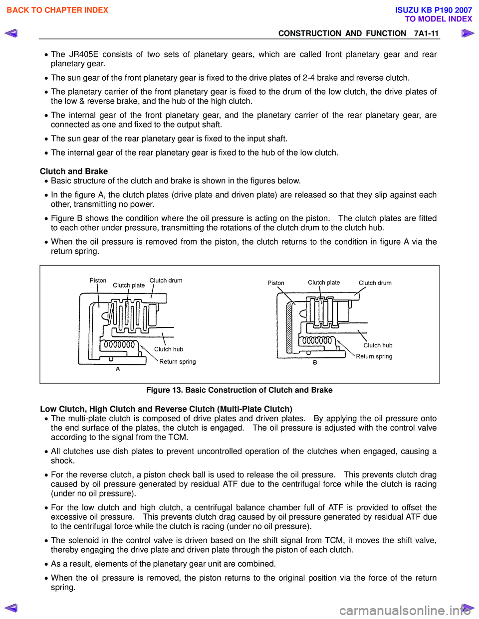
Clutch and Brake • Basic structure of the clutch and brake is shown in the figures below.
• In the figure A, the clutch plates (drive plate and driven plate) are released so that they slip against each
other, transmitting no power.
• Figure B shows the condition where the oil pressure is acting on the piston. The clutch plates are fitted
to each other under pressure, transmitting the rotations of the clutch drum to the clutch hub.
• When the oil pressure is removed from the piston, the clutch returns to the condition in figure A via the
return spring.
Figure 13. Basic Construction of Clutch and Brake
Low Clutch, High Clutch and Reverse Clutch (Multi-Plate Clutch) • The multi-plate clutch is composed of drive plates and driven plates. By applying the oil pressure onto
the end surface of the plates, the clutch is engaged. The oil pressure is adjusted with the control valve
according to the signal from the TCM.
• All clutches use dish plates to prevent uncontrolled operation of the clutches when engaged, causing a
shock.
• For the reverse clutch, a piston check ball is used to release the oil pressure. This prevents clutch drag
caused by oil pressure generated by residual ATF due to the centrifugal force while the clutch is racing
(under no oil pressure).
• For the low clutch and high clutch, a centrifugal balance chamber full of ATF is provided to offset the
excessive oil pressure. This prevents clutch drag caused by oil pressure generated by residual ATF due
to the centrifugal force while the clutch is racing (under no oil pressure).
• The solenoid in the control valve is driven based on the shift signal from TCM, it moves the shift valve,
thereby engaging the drive plate and driven plate through the piston of each clutch.
• As a result, elements of the planetary gear unit are combined.
• When the oil pressure is removed, the piston returns to the original position via the force of the return
spring.
BACK TO CHAPTER INDEX
TO MODEL INDEX
ISUZU KB P190 2007
Page 4252 of 6020
CONSTRUCTION AND FUNCTION 7A1-13
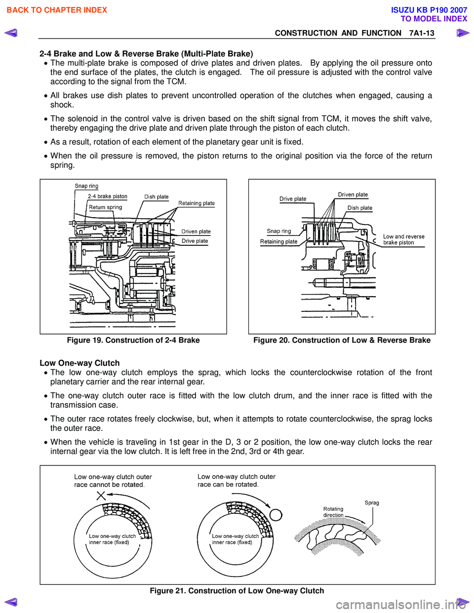
2-4 Brake and Low & Reverse Brake (Multi-Plate Brake) • The multi-plate brake is composed of drive plates and driven plates. By applying the oil pressure onto
the end surface of the plates, the clutch is engaged. The oil pressure is adjusted with the control valve
according to the signal from the TCM.
• All brakes use dish plates to prevent uncontrolled operation of the clutches when engaged, causing a
shock.
• The solenoid in the control valve is driven based on the shift signal from TCM, it moves the shift valve,
thereby engaging the drive plate and driven plate through the piston of each clutch.
• As a result, rotation of each element of the planetary gear unit is fixed.
• When the oil pressure is removed, the piston returns to the original position via the force of the return
spring.
Figure 19. Construction of 2-4 Brake
Figure 20. Construction of Low & Reverse Brake
Low One-way Clutch
• The low one-way clutch employs the sprag, which locks the counterclockwise rotation of the front
planetary carrier and the rear internal gear.
• The one-way clutch outer race is fitted with the low clutch drum, and the inner race is fitted with the
transmission case.
• The outer race rotates freely clockwise, but, when it attempts to rotate counterclockwise, the sprag locks
the outer race.
• When the vehicle is traveling in 1st gear in the D, 3 or 2 position, the low one-way clutch locks the rear
internal gear via the low clutch. It is left free in the 2nd, 3rd or 4th gear.
Figure 21. Construction of Low One-way Clutch
BACK TO CHAPTER INDEX
TO MODEL INDEX
ISUZU KB P190 2007
Page 4254 of 6020
CONSTRUCTION AND FUNCTION 7A1-15
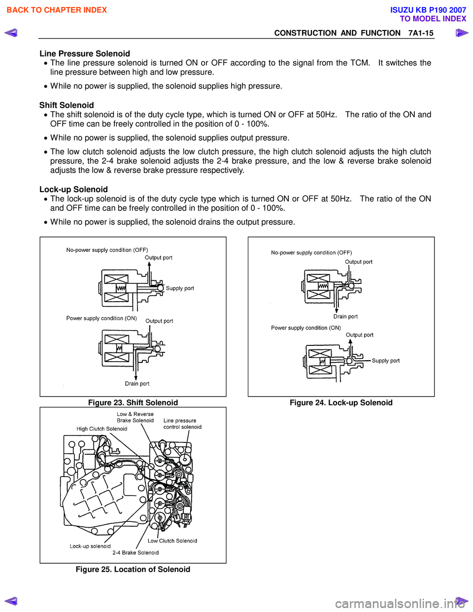
Line Pressure Solenoid • The line pressure solenoid is turned ON or OFF according to the signal from the TCM. It switches the
line pressure between high and low pressure.
• While no power is supplied, the solenoid supplies high pressure.
Shift Solenoid • The shift solenoid is of the duty cycle type, which is turned ON or OFF at 50Hz. The ratio of the ON and
OFF time can be freely controlled in the position of 0 - 100%.
• While no power is supplied, the solenoid supplies output pressure.
• The low clutch solenoid adjusts the low clutch pressure, the high clutch solenoid adjusts the high clutch
pressure, the 2-4 brake solenoid adjusts the 2-4 brake pressure, and the low & reverse brake solenoid
adjusts the low & reverse brake pressure respectively.
Lock-up Solenoid • The lock-up solenoid is of the duty cycle type which is turned ON or OFF at 50Hz. The ratio of the ON
and OFF time can be freely controlled in the position of 0 - 100%.
• While no power is supplied, the solenoid drains the output pressure.
Figure 23. Shift Solenoid Figure 24. Lock-up Solenoid
Figure 25. Location of Solenoid
BACK TO CHAPTER INDEX
TO MODEL INDEX
ISUZU KB P190 2007
Page 4261 of 6020
7A1-22 CONSTRUCTION AND FUNCTION
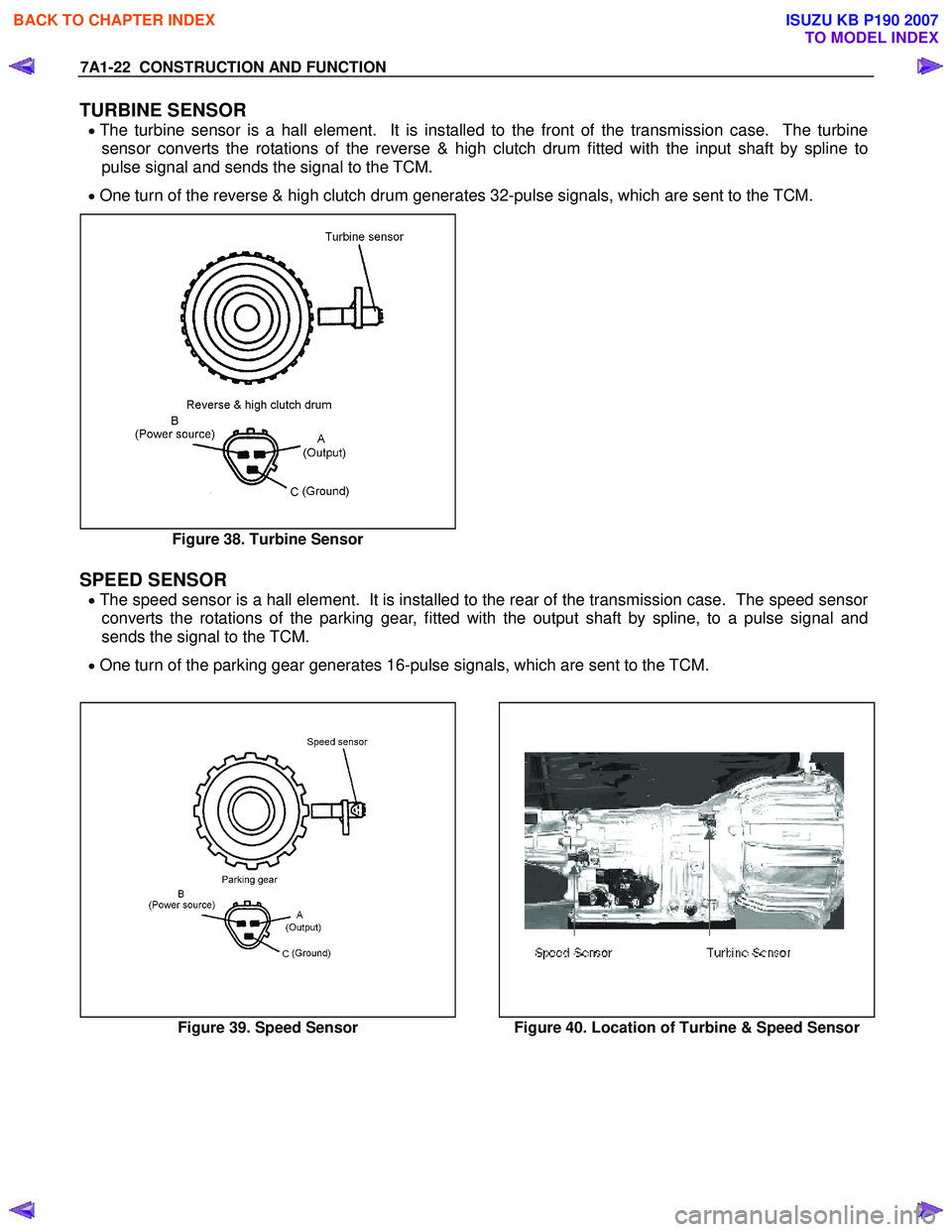
TURBINE SENSOR
• The turbine sensor is a hall element. It is installed to the front of the transmission case. The turbine
sensor converts the rotations of the reverse & high clutch drum fitted with the input shaft by spline to
pulse signal and sends the signal to the TCM.
• One turn of the reverse & high clutch drum generates 32-pulse signals, which are sent to the TCM.
Figure 38. Turbine Sensor
SPEED SENSOR
• The speed sensor is a hall element. It is installed to the rear of the transmission case. The speed sensor
converts the rotations of the parking gear, fitted with the output shaft by spline, to a pulse signal and
sends the signal to the TCM.
• One turn of the parking gear generates 16-pulse signals, which are sent to the TCM.
Figure 39. Speed Sensor Figure 40. Location of Turbine & Speed Sensor
BACK TO CHAPTER INDEX
TO MODEL INDEX
ISUZU KB P190 2007
Page 4263 of 6020
7A1-24 CONSTRUCTION AND FUNCTION
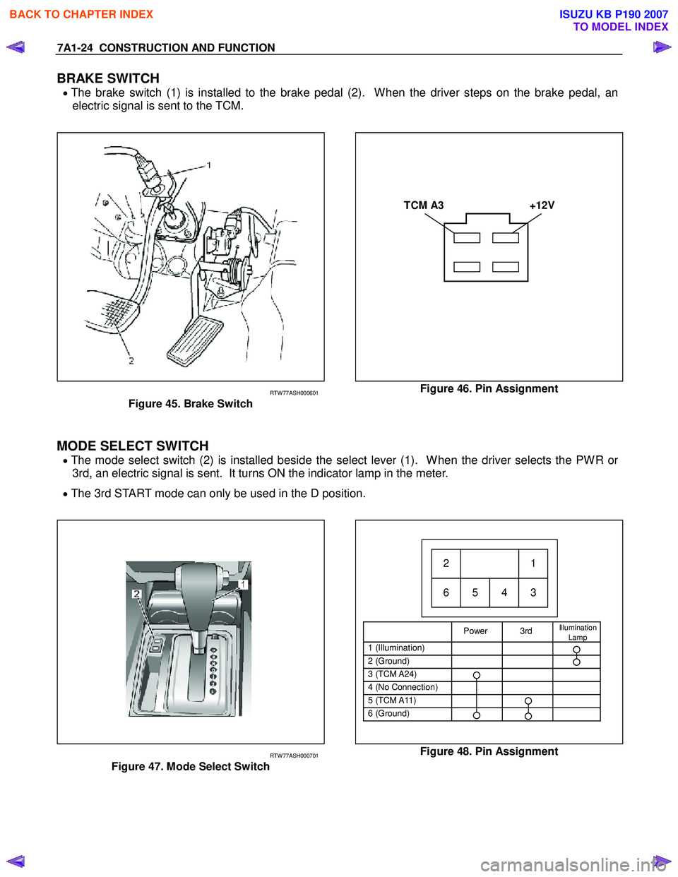
BRAKE SWITCH
• The brake switch (1) is installed to the brake pedal (2). When the driver steps on the brake pedal, an
electric signal is sent to the TCM.
TCM A3 +12V
RTW 77ASH000601
Figure 45. Brake Switch
Figure 46. Pin Assignment
MODE SELECT SWITCH
• The mode select switch (2) is installed beside the select lever (1). When the driver selects the PWR or
3rd, an electric signal is sent. It turns ON the indicator lamp in the meter.
• The 3rd START mode can only be used in the D position.
Power 3rd Illumination
Lamp
1 (Illumination)
2 (Ground)
3 (TCM A24)
4 (No Connection)
5 (TCM A11)
6 (Ground)
21
65 4 3
RTW 77ASH000701
Figure 47. Mode Select Switch
Figure 48. Pin Assignment
BACK TO CHAPTER INDEX
TO MODEL INDEX
ISUZU KB P190 2007
Page 4265 of 6020
7A1-26 CONSTRUCTION AND FUNCTION
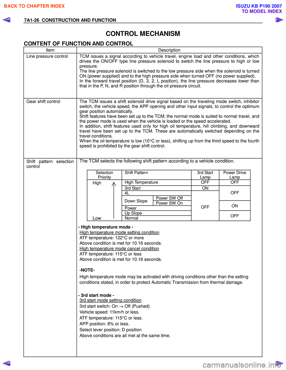
CONTROL MECHANISM
CONTENT OF FUNCTION AND CONTROL
Item Description
Line pressure control TCM issues a signal according to vehicle travel, engine load and other conditions, which
drives the ON/OFF type line pressure solenoid to switch the line pressure to high or low
pressure.
The line pressure solenoid is switched to the low pressure side when the solenoid is turned
ON (power supplied) and to the high pressure side when turned OFF (no power supplied).
In the forward travel position (D, 3, 2, L position), the line pressure decreases lower than
that in the P, N, and R position through the oil pressure circuit.
Gear shift control The TCM issues a shift solenoid drive signal based on the traveling mode switch, inhibitor
switch, the vehicle speed, the APP opening and other input signals, to control the optimum
gear position automatically.
Shift features have been set up to the TCM; the normal mode is suited to normal travel, and
the power mode is used when the vehicle is loaded or the speed accelerated.
In addition, shift features used only for high oil temperature, hill climbing, and downward
travel have been set up to the TCM. These are automatically switched depending on the
travel conditions.
W hen the oil temperature is low (10°C or less), shifting up from the third speed to the fourth
speed is prohibited by the gear shift control.
Shift pattern selection
control
The TCM selects the following shift pattern according to a vehicle condition.
Selection
Priority Shift Pattern 3rd Start
Lamp Power Drive
Lamp
High High Temperature OFF OFF
3rd Start ON
4L
Power SW Off
OFF
Down Slope
Power SW On
Power ON
Up Slope
Low Normal
OFF
OFF
- High temperature mode -
High temperature mode setting condition
ATF temperature: 122 °C or more
Above condition is met for 10.16 seconds.
High temperature mode cancel condition
ATF temperature: 115 °C or less
Above condition is met for 10.16 seconds.
-NOTE-
High temperature mode may be activated with driving conditions other than the setting
conditions stated, in order to protect Automatic Transmission from thermal damage.
- 3rd start mode -
3rd start mode setting condition
3rd start switch: On → Off (Pushed)
Vehicle speed: 11km/h or less.
ATF temperature: 115 °C or less.
APP position: 8% or less.
Select lever position: D position
Above conditions are all met at the same time.
BACK TO CHAPTER INDEX
TO MODEL INDEX
ISUZU KB P190 2007