Page 144 of 6020

Replace
YES
• Are the A/C thermo (X-15),")
1-110 HEATER AND AIR CONDITIONING
MAGNETIC CLUTCH DOES NOT RUN (4JJ1-TC Standard Output, 4JJ1-TC
High Output, 4JK1-TC High Output LHD MODEL)
Replace
YES
• Are the A/C thermo (X-15), heater & A/C (X-11) and
A/C compressor (X-14) relay OK?
• Are the No. SBF-6 fuse (30A) and the No. EB-13
(10A) fuses OK?
YES
• Is the pressure switch (C-24) OK?
YES
• Are the A/C switch (B-57) and the fan switch (B-13)
OK?
NO
YES
• Is there continuity between the engine harness
connector terminal No.1 (E-3) and the engine room
harness connector terminal No.2 (X-14)?
• Disconnect the A/C compressor relay.
• Turn the ignition switch "ON" (Engine is running)
• A/C switch and fan control knob (fan switch) "ON"
NO
Replace
NO
Defective switch or insufficient
refrigerant
NO
NO
Does the magnetic clutch
operate?
YES
Replace
• Disconnect the magnetic clutch connector.
• Is there battery voltage between the engine room
harness connector terminal No.1 (E-3) and ground?
Defective compressor
YESNO
Defective magnetic clutch
• Is the electronic thermostat (C-55) OK?
YES
Replace
NO
BACK TO CHAPTER INDEX
TO MODEL INDEX
ISUZU KB P190 2007
Page 149 of 6020

Replace
YES
• Are the A/C thermo (X-15), heater & A/C (X-11)
and A/C compressor (X-14) relay OK?
• Are the No. SB")
HEATER AND AIR CONDITIONING 1-115
MAGNETIC CLUTCH DOES NOT RUN (C24SE)
Replace
YES
• Are the A/C thermo (X-15), heater & A/C (X-11)
and A/C compressor (X-14) relay OK?
• Are the No. SBF 8 fuse (30A) and the No. EB-13
(10A) fuses OK?
YES
• Is the pressure switch (C-24) OK?
YES
• Are the A/C switch (B-57) and the fan switch (B-13)
OK?
NO
YES
• Is there continuity between the engine harness
connector terminal No.1 (E-2) and the engine room
harness connector terminal No.2 (X-14)?
• Disconnect the A/C compressor relay.
• Turn the ignition switch "ON" (Engine is running)
• A/C switch and fan control knob (fan switch "ON")
NO
Replace
NO
Defective switch or insufficient
refrigerant
NO
NO
Does the magnetic clutch
operate?
YES
Replace
• Disconnect the magnetic clutch connector.
• Is there battery voltage between the engine room
harness connector terminal No.1 (E-2) and ground?
Defective compressor
YESNO
Defective magnetic clutch
• Is the electronic thermostat (C-55) OK?
Replace
NOYES
BACK TO CHAPTER INDEX
TO MODEL INDEX
ISUZU KB P190 2007
Page 153 of 6020
HEATER AND AIR CONDITIONING 1-119
SPECIAL SERVICE TOOL
ILLUSTRATION PART NO. PART NAME
5-8840-0629-0 (J-39500-A)
5-8840-0630-0
(J-39500-220A)
5-8840-0631-0
(J-39500-220ANZ)
5-8840-4056-0 (J-37872)
Drive plate holder
5-8840-0121-0 (J-33943)
Clutch pulley puller pilot
5-8840-0111-0 (J-8433)
Clutch pulley puller
5-8840-0118-0 (J-33940)
Clutch pulley installer
5-8840-0007-0 (J-8092)
Driver handle
BACK TO CHAPTER INDEX
TO MODEL INDEX
ISUZU KB P190 2007
Page 557 of 6020
FRONT WHEEL DRIVE 4C1-53
FRONT HUB AND DISC
(4 ×
××
×
4 Manual Locking Hub Model)
DISASSEMBLY
Refer to SECTION 3E “WHEELS AND TIRES” for wheel removal procedure
RTW 440LF00030 1
Disassembly Steps
� 1 . Bolt
2. Cover assembly
3. Snap ring and shim
4. Body assembly
5. Lock washer
� 6. Hub nut
� 7. Hub and disc assembly
8. Outer bearing
9. Oil seal
10. Inner bearing
11. ABS sensor rotor
� 1 2. Bolt
� 13. W heel pin
�
1 4. Clutch assembly
15. Snap ring
16. Knob
17. Compression spring
18. Follower
� 1 9. Retaining spring
20. X-ring
2 1. Snap ring
22. Inner assembly
23. Snap ring
24. Ring
25. Spacer
BACK TO CHAPTER INDEX
TO MODEL INDEX
ISUZU KB P190 2007
Page 558 of 6020
4C1-54 FRONT WHEEL DRIVE
Important Operations
1. Bolt
Before removal, shift transfer lever into “2H” position and set
free wheeling hub knob into “FREE” position.
6. Hub nut
W rench : 5-8840-2 117-0
7. Hub and disc assembly
Before disassembly, remove the disc brake caliper assembly
and hang it on the frame with wires.
Refer to Section “Brake” for disc brake caliper removal
procedure.
14. Clutch Assembly
W hile pushing follower knob, turn clutch assembly clockwise
and then remove clutch assembly from knob.
19. Retaining Spring
Remove retaining spring from clutch assembly by turning it
counterclockwise.
BACK TO CHAPTER INDEX
TO MODEL INDEX
ISUZU KB P190 2007
Page 560 of 6020
4C1-56 FRONT WHEEL DRIVE
INSPECTION AND REPAIR
Make necessary correction or parts replacement if wear, damage or any other abnormal conditions are found
through inspection.
For inspection and servicing of disc caliper, and relative parts, and ABS parts, refer to Section Brakes.
• Hub
• Hub bearing, oil seal
• Knuckle spindle
• Disc
• Caliper
• ABS sensor rotor
• Cap, Hub flange, Shim, Snap ring
• Free wheeling hub parts (Option)
• Clutch, Knob, follower, inner, ring and
spring
Visual Check
Check the following parts for wear, damage or other abnormal
conditions.
BACK TO CHAPTER INDEX
TO MODEL INDEX
ISUZU KB P190 2007
Page 561 of 6020
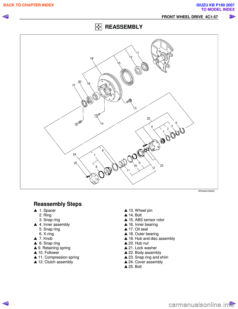
FRONT WHEEL DRIVE 4C1-57
REASSEMBLY
RTW 440LF00040 1
Reassembly Steps
� 1 . Spacer
2. Ring
3. Snap ring
� 4. Inner assembly
5. Snap ring
6. X-ring
� 7. Knob
� 8. Snap ring
� 9. Retaining spring
� 1 0. Follower
� 11 . Compression spring
� 1 2. Clutch assembly
�
1 3. W heel pin
� 1 4. Bolt
� 1 5. ABS sensor rotor
� 1 6. Inner bearing
� 1 7. Oil seal
� 1 8. Outer bearing
� 1 9. Hub and disc assembly
� 20. Hub nut
� 21. Lock washer
� 22. Body assembly
� 23. Snap ring and shim
� 24. Cover assembly
� 25. Bolt
BACK TO CHAPTER INDEX
TO MODEL INDEX
ISUZU KB P190 2007
Page 562 of 6020

Amount o")
4C1-58 FRONT WHEEL DRIVE
Important Operations
1. Spacer
Apply grease to both faces of spacer.
4. Inner Assembly
Apply grease wheel bearing to inside face of ring.
g(oz)
Amount of grease 6 (0.21)
7. Knob
( 1 ) Apply grease W heel bearing to outer circumference of knob
and inner circumference of cover.
(2) Align detent ball to either groove of cover.
8. Snap Ring
Turn the smoother face to knob side.
9. Retaining Spring
Align the end of spring to the end of cut portion of clutch spring
groove.
10. Follower
Install follower to clutch so that follower nail will come closer to
the bent portion of retaining spring by aligning follower stopper
nail to outer teeth of clutch. Then, hook retaining spring onto
upper portion of hanger nails of follower.
11. Compression Spring
Turn the smaller diameter side to follower.
12. Clutch Assembly
Align follower nail to handle groove, and then assemble clutch
with knob by pushing and turning clutch counterclockwise to
knob.
BACK TO CHAPTER INDEX
TO MODEL INDEX
ISUZU KB P190 2007

5-8840-0630-0
(J-39500-220A)
5-8840-0631-0")

DISASSEMBLY
Refer to SECTION 3E “WHEELS AND TIRES” for wheel removal procedure
RTW 440LF000")