Page 5597 of 6020

Cruise Control – HFV6 Page 8C–19
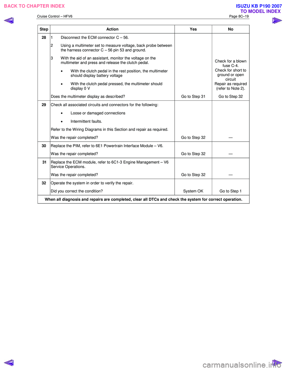
Step Action Yes No
28 1 Disconnect the ECM connector C – 56.
2 Using a multimeter set to measure voltage, back probe between the harness connector C – 56 pin 53 and ground.
3 W ith the aid of an assistant, monitor the voltage on the multimeter and press and release the clutch pedal.
• With the clutch pedal in the rest position, the multimeter
should display battery voltage
• W ith the clutch pedal pressed, the multimeter should
display 0 V
Does the multimeter display as described? Go to Step 31 Check for a blown
fuse C-4.
Check for short to ground or open circuit
Repair as required (refer to Note 2).
Go to Step 32
29 Check all associated circuits and connectors for the following:
• Loose or damaged connections
• Intermittent faults.
Refer to the Wiring Diagrams in this Section and repair as required.
W as the repair completed? Go to Step 32 —
30 Replace the PIM, refer to 6E1 Powertrain Interface Module – V6.
W as the repair completed? Go to Step 32 —
31 Replace the ECM module, refer to 6C1-3 Engine Management – V6
Service Operations.
W as the repair completed? Go to Step 32 —
32 Operate the system in order to verify the repair.
Did you correct the condition? System OK Go to Step 1
When all diagnosis and repairs are completed, clear all DTCs and check the system for correct operation.
BACK TO CHAPTER INDEX
TO MODEL INDEXISUZU KB P190 2007
Page 5602 of 6020
Cruise Control – HFV6 Page 8C–24
3.4 Clutch Pedal Switch (Manual Only)
Remove
1 Disconnect the electrical connector (1) from the clutch
switch (2).
2 Loosen the lock nut (3) and remove the clutch switch from the pedal bracket.
Figure 8C – 13
Test
1 Using a multimeter set to measure ohms, probe the pins (1) of the switch assembly.
2 In the neutral position (plunger extended) there should be an open circuit across the switch.
3 In the active position (plunger extended) there should be a closed circuit across the switch.
4 Replace the switch as per the following reinstall procedure if the tests prove the switch to be faulty.
5 If the test proves the switch to be serviceable, reinstall it as per the following procedure.
Figure 8C – 14
BACK TO CHAPTER INDEX TO MODEL INDEXISUZU KB P190 2007
Page 5603 of 6020
Cruise Control – HFV6 Page 8C–25
Reinstall
6 Install the clutch switch (1) as follows:
a Insert the switch into the clutch pedal bracket.
b Rotate the switch clockwise until obtaining the clearance (2) between the pedal (3) and the
pedal stoper.
Clutch pedal and pedal stoper
clearance specification............................... 0.5 – 1.5 mm
c Tighten the lock nut (4) to the correct torque specification.
Clutch switch lock nut
torque specification ............................................ 31.0 Nm
d Recheck the clutch switch clearance, readjust clearance if required.
NOTE
No adjustment is required for the clutch switch
itself.
Figure 8C – 15
7 Reconnect the electrical connector to the clutch switch.
8 Verify the operation of the clutch switch by operating the cruise control and checking the clutch switch stops operation of the cruise control when the clutch pedal is pressed.
BACK TO CHAPTER INDEX TO MODEL INDEXISUZU KB P190 2007