Page 5712 of 6020

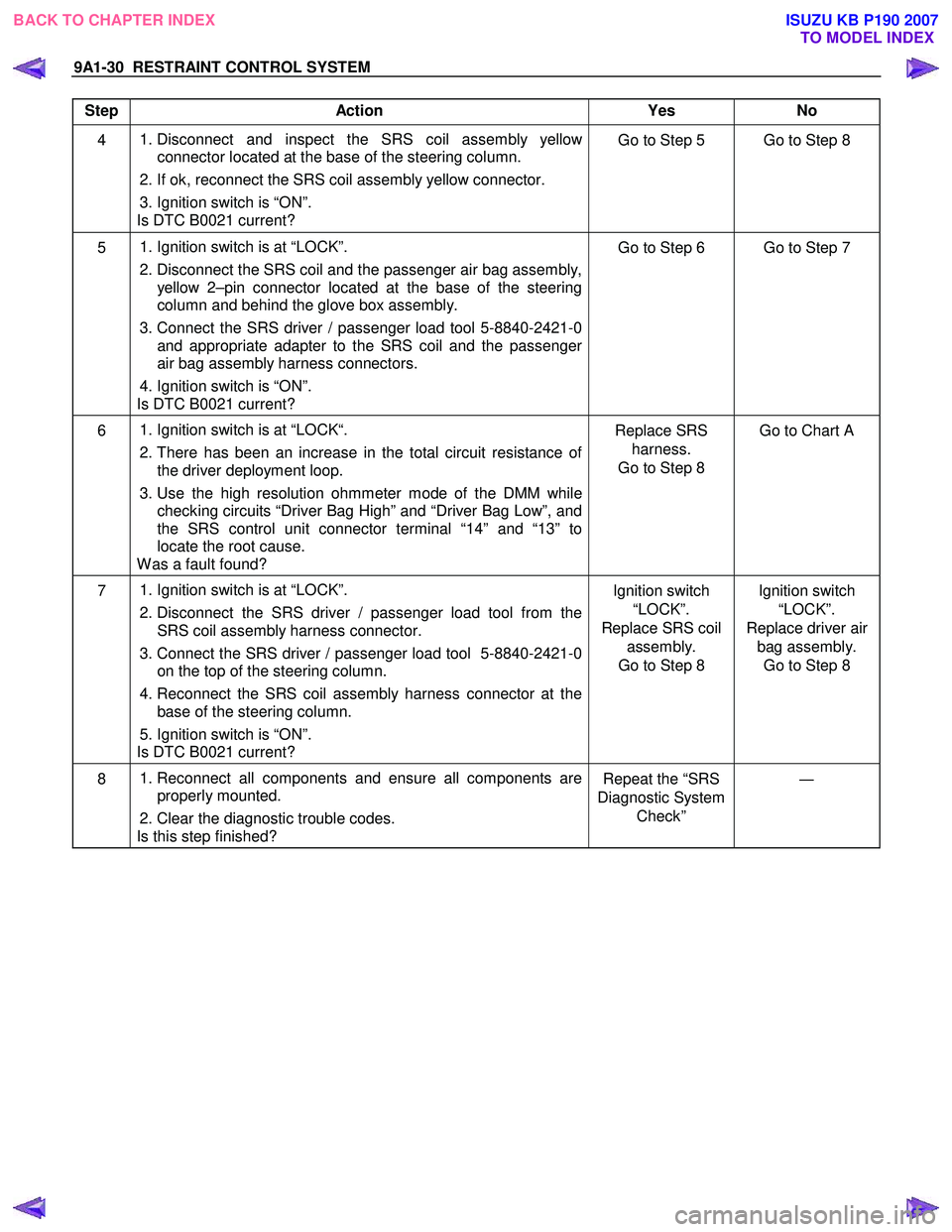
9A1-30 RESTRAINT CONTROL SYSTEM
Step Action Yes No
4
1. Disconnect and inspect the SRS coil assembly yellow
connector located at the base of the steering column.
2. If ok, reconnect the SRS coil assembly yellow connector.
3. Ignition switch is “ON”.
Is DTC B0021 current? Go to Step 5 Go to Step 8
5
1. Ignition switch is at “LOCK”.
2. Disconnect the SRS coil and the passenger air bag assembly,
yellow 2–pin connector located at the base of the steering
column and behind the glove box assembly.
3. Connect the SRS driver / passenger load tool 5-8840-2421-0
and appropriate adapter to the SRS coil and the passenger
air bag assembly harness connectors.
4. Ignition switch is “ON”.
Is DTC B0021 current? Go to Step 6 Go to Step 7
6
1. Ignition switch is at “LOCK“.
2. There has been an increase in the total circuit resistance of
the driver deployment loop.
3. Use the high resolution ohmmeter mode of the DMM while
checking circuits “Driver Bag High” and “Driver Bag Low”, and
the SRS control unit connector terminal “14” and “13” to
locate the root cause.
W as a fault found? Replace SRS
harness.
Go to Step 8 Go to Chart A
7
1. Ignition switch is at “LOCK”.
2. Disconnect the SRS driver / passenger load tool from the
SRS coil assembly harness connector.
3. Connect the SRS driver / passenger load tool 5-8840-2421-0 on the top of the steering column.
4. Reconnect the SRS coil assembly harness connector at the
base of the steering column.
5. Ignition switch is “ON”.
Is DTC B0021 current? Ignition switch
“LOCK”.
Replace SRS coil assembly.
Go to Step 8 Ignition switch
“LOCK”.
Replace driver air bag assembly. Go to Step 8
8
1. Reconnect all components and ensure all components are
properly mounted.
2. Clear the diagnostic trouble codes.
Is this step finished? Repeat the “SRS
Diagnostic System Check” ―
BACK TO CHAPTER INDEX
TO MODEL INDEX
ISUZU KB P190 2007
Page 5715 of 6020

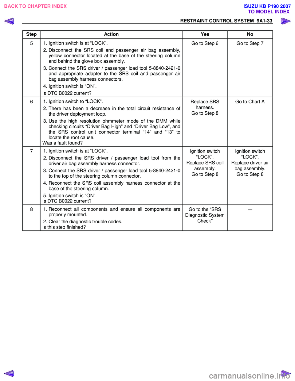
RESTRAINT CONTROL SYSTEM 9A1-33
Step Action Yes No
5 1. Ignition switch is at “LOCK”.
2. Disconnect the SRS coil and passenger air bag assembly, yellow connector located at the base of the steering column
and behind the glove box assembly.
3. Connect the SRS driver / passenger load tool 5-8840-2421-0 and appropriate adapter to the SRS coil and passenger air
bag assembly harness connectors.
4. Ignition switch is “ON”.
Is DTC B0022 current? Go to Step 6 Go to Step 7
6
1. Ignition switch to “LOCK”.
2. There has been a decrease in the total circuit resistance of
the driver deployment loop.
3. Use the high resolution ohmmeter mode of the DMM while
checking circuits “Driver Bag High” and “Driver Bag Low”, and
the SRS control unit connector terminal “14” and “13” to
locate the root cause.
W as a fault found? Replace SRS
harness.
Go to Step 8 Go to Chart A
7
1. Ignition switch is at “LOCK”.
2. Disconnect the SRS driver / passenger load tool from the
driver air bag assembly harness connector.
3. Connect the SRS driver / passenger load tool 5-8840-2421-0 to the top of the steering column connector.
4. Reconnect the SRS coil assembly harness connector at the
base of the steering column.
5. Ignition switch is “ON”.
Is DTC B0022 current? Ignition switch
“LOCK”.
Replace SRS coil assembly.
Go to Step 8 Ignition switch
“LOCK”.
Replace driver air bag assembly. Go to Step 8
8
1. Reconnect all components and ensure all components are
properly mounted.
2. Clear the diagnostic trouble codes.
Is this step finished? Go to the “SRS
Diagnostic System Check” ―
BACK TO CHAPTER INDEX
TO MODEL INDEX
ISUZU KB P190 2007
Page 5727 of 6020

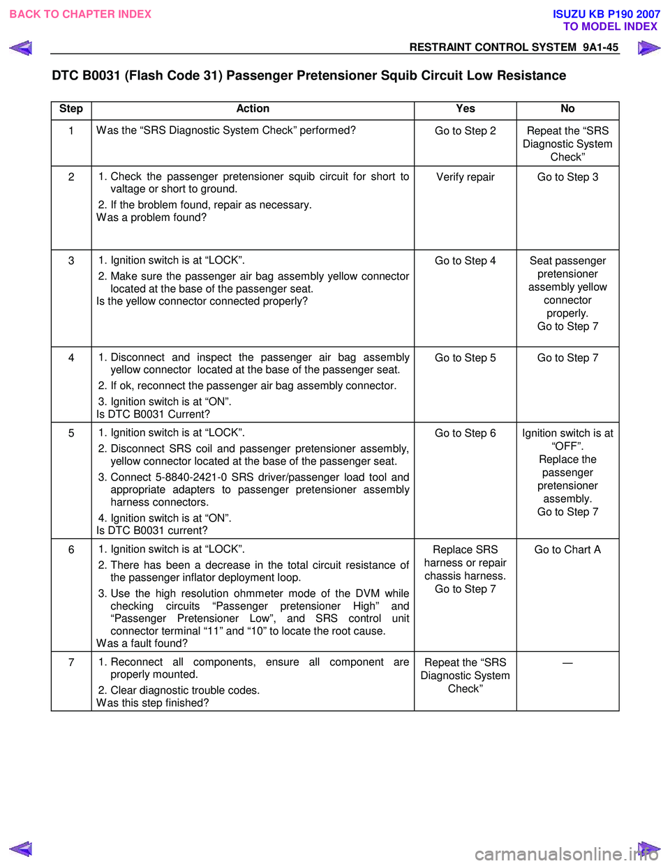
RESTRAINT CONTROL SYSTEM 9A1-45
DTC B0031 (Flash Code 31) Passenger Pretensioner Squib Circuit Low Resistance
Step Action Yes No
1 W as the “SRS Diagnostic System Check” performed?
Go to Step 2 Repeat the “SRS
Diagnostic System Check”
2
1. Check the passenger pretensioner squib circuit for short to
valtage or short to ground.
2. If the broblem found, repair as necessary.
W as a problem found? Verify repair Go to Step 3
3
1. Ignition switch is at “LOCK”.
2. Make sure the passenger air bag assembly yellow connector
located at the base of the passenger seat.
Is the yellow connector connected properly? Go to Step 4 Seat passenger
pretensioner
assembly yellow connector properly.
Go to Step 7
4
1. Disconnect and inspect the passenger air bag assembly
yellow connector located at the base of the passenger seat.
2. If ok, reconnect the passenger air bag assembly connector.
3. Ignition switch is at “ON”.
Is DTC B0031 Current? Go to Step 5 Go to Step 7
5
1. Ignition switch is at “LOCK”.
2. Disconnect SRS coil and passenger pretensioner assembly,
yellow connector located at the base of the passenger seat.
3. Connect 5-8840-2421-0 SRS driver/passenger load tool and
appropriate adapters to passenger pretensioner assembly
harness connectors.
4. Ignition switch is at “ON”.
Is DTC B0031 current? Go to Step 6 Ignition switch is at
“OFF”.
Replace the passenger
pretensioner assembly.
Go to Step 7
6
1. Ignition switch is at “LOCK”.
2. There has been a decrease in the total circuit resistance of
the passenger inflator deployment loop.
3. Use the high resolution ohmmeter mode of the DVM while checking circuits “Passenger pretensioner High” and
“Passenger Pretensioner Low”, and SRS control unit
connector terminal “11” and “10” to locate the root cause.
W as a fault found? Replace SRS
harness or repair chassis harness. Go to Step 7 Go to Chart A
7
1. Reconnect all components, ensure all component are
properly mounted.
2. Clear diagnostic trouble codes.
W as this step finished? Repeat the “SRS
Diagnostic System Check” ―
BACK TO CHAPTER INDEX
TO MODEL INDEX
ISUZU KB P190 2007
Page 5735 of 6020

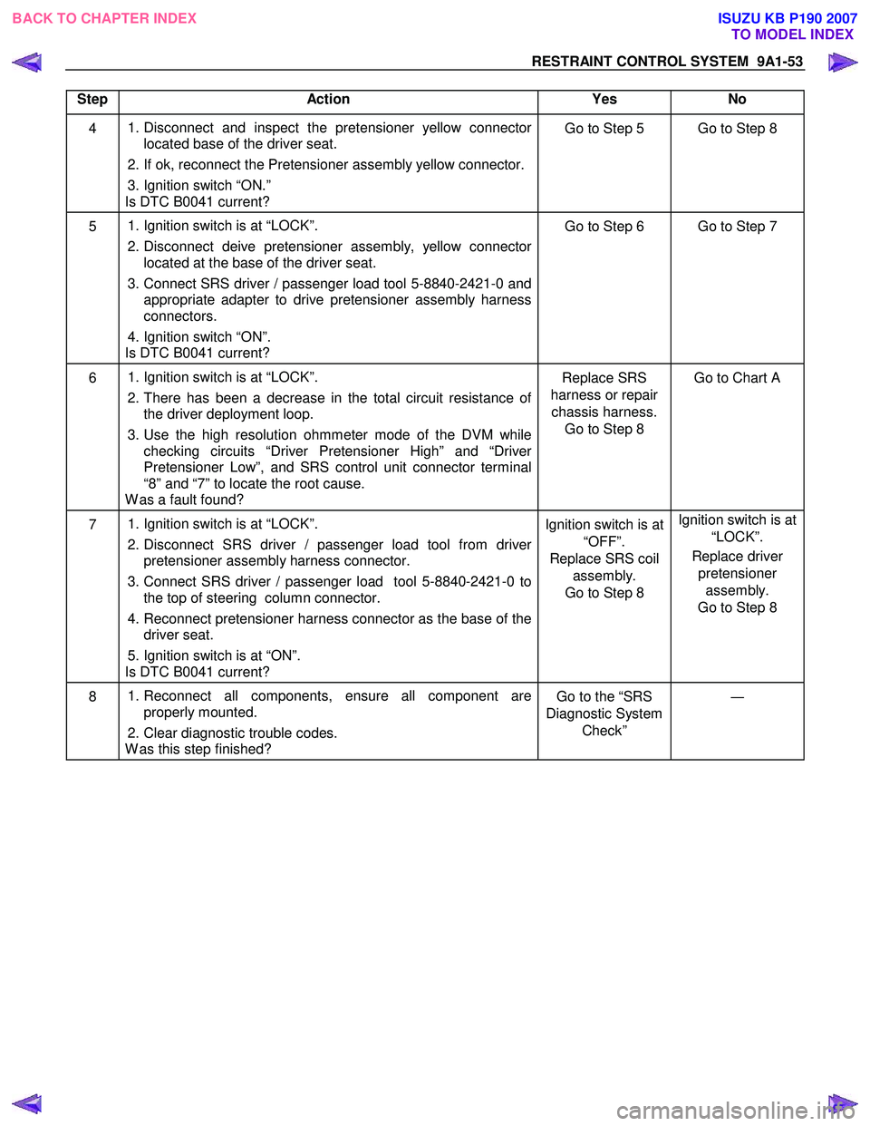
RESTRAINT CONTROL SYSTEM 9A1-53
Step Action Yes No
4
1. Disconnect and inspect the pretensioner yellow connector
located base of the driver seat.
2. If ok, reconnect the Pretensioner assembly yellow connector.
3. Ignition switch “ON.”
Is DTC B0041 current? Go to Step 5 Go to Step 8
5
1. Ignition switch is at “LOCK”.
2. Disconnect deive pretensioner assembly, yellow connector
located at the base of the driver seat.
3. Connect SRS driver / passenger load tool 5-8840-2421-0 and
appropriate adapter to drive pretensioner assembly harness
connectors.
4. Ignition switch “ON”.
Is DTC B0041 current? Go to Step 6 Go to Step 7
6
1. Ignition switch is at “LOCK”.
2. There has been a decrease in the total circuit resistance of
the driver deployment loop.
3. Use the high resolution ohmmeter mode of the DVM while
checking circuits “Driver Pretensioner High” and “Driver
Pretensioner Low”, and SRS control unit connector terminal
“8” and “7” to locate the root cause.
W as a fault found? Replace SRS
harness or repair chassis harness. Go to Step 8 Go to Chart A
7
1. Ignition switch is at “LOCK”.
2. Disconnect SRS driver / passenger load tool from driver
pretensioner assembly harness connector.
3. Connect SRS driver / passenger load tool 5-8840-2421-0 to the top of steering column connector.
4. Reconnect pretensioner harness connector as the base of the
driver seat.
5. Ignition switch is at “ON”.
Is DTC B0041 current? Ignition switch is at
“OFF”.
Replace SRS coil assembly.
Go to Step 8 Ignition switch is at
“LOCK”.
Replace driver pretensioner assembly.
Go to Step 8
8
1. Reconnect all components, ensure all component are
properly mounted.
2. Clear diagnostic trouble codes.
W as this step finished? Go to the “SRS
Diagnostic System Check” ―
BACK TO CHAPTER INDEX
TO MODEL INDEX
ISUZU KB P190 2007
Page:
< prev 1-8 9-16 17-24