2007 ISUZU KB P190 checking oil
[x] Cancel search: checking oilPage 3765 of 6020
Automatic Transmission – 4L60E – General Information Page 7C1–5
Clean and Inspect
Do not use solvents on neoprene seals,
composition faced clutch plates or thrust
washers as damage to parts may occur.
After complete disassembly of a component, wash all metal parts in a clean solvent and dry with compressed air. Blow
oil passages out and check to make sure they are not obstructed, small passages should be checked with tag wire. All
parts should be inspected to determine if replacement is required.
Pay particular attention to the following:
• Inspect linkage and pivot points for excessive wear.
• Bearing and thrust surfaces of all parts should be checked for excessive wear and scoring.
• Check for broken seal rings, damaged ring lands and damaged threads.
• Inspect seals for damage.
• Mating surfaces of castings should be checked for burrs. Irregularities may be removed by lapping the surface with
emery paper laid on a flat surface, such as a piece of plate glass.
• Castings should be checked for cracks and porosity.
1.3 7C2 Automatic Transmission – 4L60E –
Electrical Diagnosis
For transmissions fitted to V6 engines, the electrical diagnosis is in this Section. A new electrical circuit and control
module has been introduced for automatic transmissions fitted to the V6 engines.
1.4 7C3 Automatic Transmission – 4L60E – Hydraulic and Mechanical Diagnosis
Information contained in 7C3 Automatic Transmission – 4L60E – Hydraulic and Mechanical Diagnosis will assist in the
diagnosis of the mechanical and hydraulic components in the 4L60E automatic transmission, while the transmission
remains installed on the vehicle.
Examples of the type of diagnostic information contained within this section are:
• transmission functional test,
• line pressure information,
• transmission fluid diagnosis,
• symptom diagnosis and
• shift speed charts.
1.5 7C4 Automatic Transmission – 4L60E –
On-vehicle Servicing
Information in 7C4 Automatic Transmission – 4L60E – On-vehicle Servicing covers transmission fluid level checking, as
well as specific information for servicing some components while the transmission remains installed on the vehicle. This
Section also covers the transmission removal and reinstallation to the vehicle.
BACK TO CHAPTER INDEX
TO MODEL INDEX
ISUZU KB P190 2007
Page 3785 of 6020
Automatic Transmission – 4L60E – General Information Page 7C1–25
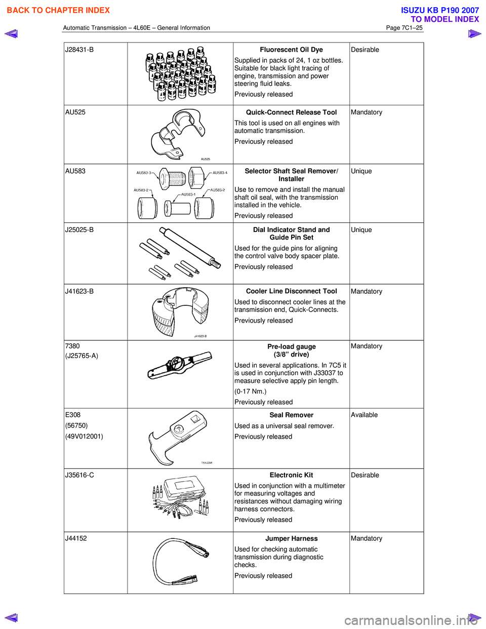
J28431-B
Fluorescent Oil Dye
Supplied in packs of 24, 1 oz bottles.
Suitable for black light tracing of
engine, transmission and power
steering fluid leaks.
Previously released Desirable
AU525
AU525 Quick-Connect Release Tool
This tool is used on all engines with
automatic transmission.
Previously released Mandatory
AU583 Selector Shaft Seal Remover/
Installer
Use to remove and install the manual
shaft oil seal, with the transmission
installed in the vehicle.
Previously released Unique
J25025-B
Dial Indicator Stand and
Guide Pin Set
Used for the guide pins for aligning
the control valve body spacer plate.
Previously released Unique
J41623-B
Cooler Line Disconnect Tool
Used to disconnect cooler lines at the
transmission end, Quick-Connects.
Previously released Mandatory
7380
(J25765-A)
Pre-load gauge
(3/8” drive)
Used in several applications. In 7C5 it
is used in conjunction with J33037 to
measure selective apply pin length.
(0-17 Nm.)
Previously released Mandatory
E308
(56750)
(49V012001)
Seal Remover
Used as a universal seal remover .
Previously released Available
J35616-C
Electronic Kit
Used in conjunction with a multimeter
for measuring voltages and
resistances without damaging wiring
harness connectors.
Previously released Desirable
J44152
Jumper Harness
Used for checking automatic
transmission during diagnostic
checks.
Previously released Mandatory
BACK TO CHAPTER INDEX
TO MODEL INDEX
ISUZU KB P190 2007
Page 3867 of 6020
Automatic Transmission – 4L60E – Electrical Diagnosis Page 7C2–81
Action Taken When the DTC Sets
• The TCM requests the ECM to illuminate the MIL during the second consecutive trip in which the conditions for
setting the DTC are met.
• The TCM commands maximum line pressure.
• The TCM freezes transmission adaptive functions.
• The TCM inhibits TCC.
• The TCM inhibits 4th gear if in hot mode.
• At the time of the first failure, the TCM records the operating conditions when the conditions for setting the DTC are
met. The TCM stores this information as a Failure Record.
• At the time of the second failure, the ECM records the operating conditions when the conditions for setting the DTC
are met. The ECM stores this information as a Freeze Frame.
• The TCM stores DTC P0894 in TCM history during the second consecutive trip in which the conditions for setting
the DTC are met.
Conditions for Clearing the DTC
• The ECM turns off the MIL after the fourth consecutive drive trip in which the TCM does not send a MIL illumination
request.
• Tech 2 can clear the DTC.
• The TCM clears the DTC from TCM history if the vehicle completes 40 warm-up cycles without a non-emission
related diagnostic fault occurring.
• The TCM cancels the DTC default actions when the ignition is off long enough to power down the TCM.
Diagnostic Aids
•
Bronze material found in the transmission oil pan may indicate stator shaft bushing wear. If bushing wear is
suspected, inspect the stator shaft and the input, turbine, shaft for damage.
• Perform the Torque Converter Diagnosis Procedure, refer to 7C3 Automatic Transmission – 4L60E – Hydraulic and
Mechanical Diagnosis.
Test Description
The following numbers refer to the step numbers in the diagnostic table:
3 Checks the torque converter for slippage while in a commanded lock-up state.
4-12 Checks the mechanical components that cause the DTC and their state.
13 W hen the TAP cells are cleared the TCM needs to relearn the TAP cells for the transmission. As such, when the vehicle is first driven, the shifts may be harsh. The transmission shifts should become smoother the more the
vehicle is driven until the TCM has relearned all TAP cells.
DTC P0894 Diagnostic Table
Step Action Yes No
1 Has the Diagnostic System Check been performed?
Go to Step 2 Refer to
4.7 Diagnostic System Check
2 Inspect for correct transmission fluid level, refer to 7C4 Automatic
Transmission – 4L60E – On-vehicle Servicing.
Did you perform the fluid checking procedure?
Go to Step 3 Check the
transmission fluid level, refer to
7C4 Automatic
Transmission –
4L60E – On-vehicle Servicing
BACK TO CHAPTER INDEX
TO MODEL INDEX
ISUZU KB P190 2007
Page 4016 of 6020
7A2-50 TRANSMISSION CONTROL SYSTEM (AW30–40LE)
Action Taken When The DTC Sets
• Control at A/T oil temperature 80 °C (176 °F).
• No squat control.
• No slope control.
• No 3rd start mode.
• No line pressure reduction at gear change.
• No coast control.
• No line pressure reduction control at garage.
• No shift solenoid functional failure detection.
• No L-up solenoid functional failure detection.
• Check Trans “ON”.
• DTC stored.
• MIL request “ON”. (EURO 4 only)
Conditions For Clearing The DTC
• The DTC can be cleared from the TCM history by
using a scan tool.
• The DTC will be cleared from history when the vehicle has achieved 40 warm-up cycles without a
failure reported.
•
After more than 1 second has elapsed after the
ignition key has been turned “ON”, short between
No.11 and No.4 (ground) of DLC (Data Link
Connector). Then, after 1 second, but within 6
seconds, discontinue shorting.
Diagnostic Aids
•
Inspect the wiring for poor electrical connection at the
TCM. Look for possible bent, backed out, deformed
or damaged terminals. Check for weak terminal
tension as well. Also check for a chafed wire that
could short to bare metal or other wiring. Inspect for a
broken wire inside the insulation.
• W hen diagnosing for a possible intermittent short o
r
open condition, move the wiring harness while
observing test equipment for a change.
• Check oil temperature sensor for proper mounting and adjustment.
Circuit/System Testing DTC P0712
Step Action Value(s) YES NO
1
W as the On-Board Diagnostic (OBD) System Check
performed? — Go to
Step 2 Go to OBD
System Check
2 Perform the transmission fluid checking procedure. Refer to checking Transmission Fluid level and
Condition in Automatic Transmission 7A section.
W as the fluid checking procedure performed? — Go to
Step 3 Refer to
Checking
Transmission
Fluid level and Condition in Automatic
Transmission
(AW 30-40LE) section
3 1. Lift the driving wheels.
2. Start the engine and place the select lever in D
position.
3. W ait for 5 minutes.
Does a scan tool indicate DTC P0712? — Go to
Step 4 Refer to
Diagnostic Aids
BACK TO CHAPTER INDEX
TO MODEL INDEX
ISUZU KB P190 2007
Page 4019 of 6020
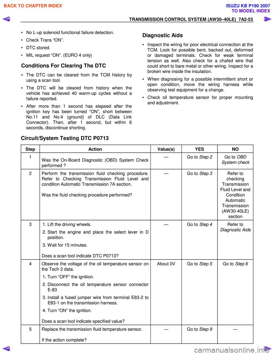
TRANSMISSION CONTROL SYSTEM (AW30–40LE) 7A2-53
• No L-up solenoid functional failure detection.
• Check Trans “ON”.
• DTC stored.
• MIL request “ON”. (EURO 4 only)
Conditions For Clearing The DTC
• The DTC can be cleared from the TCM history by
using a scan tool.
• The DTC will be cleared from history when the
vehicle has achieved 40 warm-up cycles without a
failure reported.
•
After more than 1 second has elapsed after the
ignition key has been turned “ON”, short between
No.11 and No.4 (ground) of DLC (Data Link
Connector). Then, after 1 second, but within 6
seconds, discontinue shorting.
Diagnostic Aids
•
Inspect the wiring for poor electrical connection at the
TCM. Look for possible bent, backed out, deformed
or damaged terminals. Check for weak terminal
tension as well. Also check for a chafed wire that
could short to bare metal or other wiring. Inspect for a
broken wire inside the insulation.
• W hen diagnosing for a possible intermittent short o
r
open condition, move the wiring harness while
observing test equipment for a change.
• Check oil temperature sensor for proper mounting
and adjustment.
Circuit/System Testing DTC P0713
Step Action Value(s) YES NO
1
W as the On-Board Diagnostic (OBD) System Check
performed ? — Go to
Step 2 Go to OBD
System check
2 Perform the transmission fluid checking procedure. Refer to Checking Transmission Fluid Level and
condition Automatic Transmission 7A section.
W as the fluid checking procedure performed? — Go to
Step 3 Refer to
checking
Transmission
Fluid Level and Condition
Automatic
Transmission
(AW 30-40LE) section
3 1. Lift the driving wheels.
2. Start the engine and place the select lever in D
position.
3. W ait for 15 minutes.
Does a scan tool indicate DTC P0713? — Go to
Step 4 Refer to
Diagnostic Aids
4 Observe the voltage of the oil temperature sensor on the Tech 2 data.
1. Turn “OFF” the ignition.
2. Disconnect the oil temperature sensor connector
E-83
3. Install a fused jumper wire from terminal E83-2 to E83-1 on the transmission harness.
4. Turn “ON” the ignition.
Does a scan tool indicate specified value? About 0V Go to
Step 5 Go to Step 6
5 Replace the transmission fluid temperature sensor.
If the action complete? — Go to
Step 9 —
BACK TO CHAPTER INDEX
TO MODEL INDEX
ISUZU KB P190 2007
Page 4311 of 6020
TRANSMISSION CONTROL SYSTEM (JR405E) 7A2-27
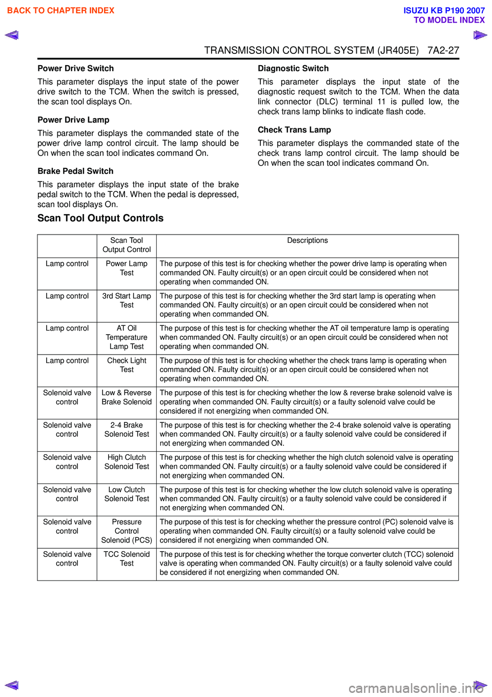
Power Drive Switch
This parameter displays the input state of the power
drive switch to the TCM. When the switch is pressed,
the scan tool displays On.
Power Drive Lamp
This parameter displays the commanded state of the
power drive lamp control circuit. The lamp should be
On when the scan tool indicates command On.
Brake Pedal Switch
This parameter displays the input state of the brake
pedal switch to the TCM. When the pedal is depressed,
scan tool displays On. Diagnostic Switch
This parameter displays the input state of the
diagnostic request switch to the TCM. When the data
link connector (DLC) terminal 11 is pulled low, the
check trans lamp blinks to indicate flash code.
Check Trans Lamp
This parameter displays the commanded state of the
check trans lamp control circuit. The lamp should be
On when the scan tool indicates command On.
Scan Tool Output Controls
Scan Tool
Output Control Descriptions
Lamp control Power Lamp Te s tThe purpose of this test is for checking whether the power drive lamp is operating when
commanded ON. Faulty circuit(s) or an open circuit could be considered when not
operating when commanded ON.
Lamp control 3rd Start Lamp Te s t The purpose of this test is for checking whether the 3rd start lamp is operating when
commanded ON. Faulty circuit(s) or an open circuit could be considered when not
operating when commanded ON.
Lamp control AT Oil Temperature
Lamp Test The purpose of this test is for checking whether the AT oil temperature lamp is operating
when commanded ON. Faulty circuit(s) or an open circuit could be considered when not
operating when commanded ON.
Lamp control Check Light Te s t The purpose of this test is for checking whether the check trans lamp is operating when
commanded ON. Faulty circuit(s) or an open circuit could be considered when not
operating when commanded ON.
Solenoid valve control Low & Reverse
Brake Solenoid The purpose of this test is for checking whether the low & reverse brake solenoid valve is
operating when commanded ON. Faulty circuit(s) or a faulty solenoid valve could be
considered if not energizing when commanded ON.
Solenoid valve control 2-4 Brake
Solenoid Test The purpose of this test is for checking whether the 2-4 brake solenoid valve is operating
when commanded ON. Faulty circuit(s) or a faulty solenoid valve could be considered if
not energizing when commanded ON.
Solenoid valve control High Clutch
Solenoid Test The purpose of this test is for checking whether the high clutch solenoid valve is operating
when commanded ON. Faulty circuit(s) or a faulty solenoid valve could be considered if
not energizing when commanded ON.
Solenoid valve control Low Clutch
Solenoid Test The purpose of this test is for checking whether the low clutch solenoid valve is operating
when commanded ON. Faulty circuit(s) or a faulty solenoid valve could be considered if
not energizing when commanded ON.
Solenoid valve control Pressure
Control
Solenoid (PCS) The purpose of this test is for checking whether the pressure control (PC) solenoid valve is
operating when commanded ON. Faulty circuit(s) or a faulty solenoid valve could be
considered if not energizing when commanded ON.
Solenoid valve control TCC Solenoid
Te s t The purpose of this test is for checking whether the torque converter clutch (TCC) solenoid
valve is operating when commanded ON. Faulty circuit(s) or a faulty solenoid valve could
be considered if not energizing when commanded ON.
BACK TO CHAPTER INDEX
TO MODEL INDEX
ISUZU KB P190 2007
Page 4336 of 6020
7A2-52 TRANSMISSION CONTROL SYSTEM (JR405E)
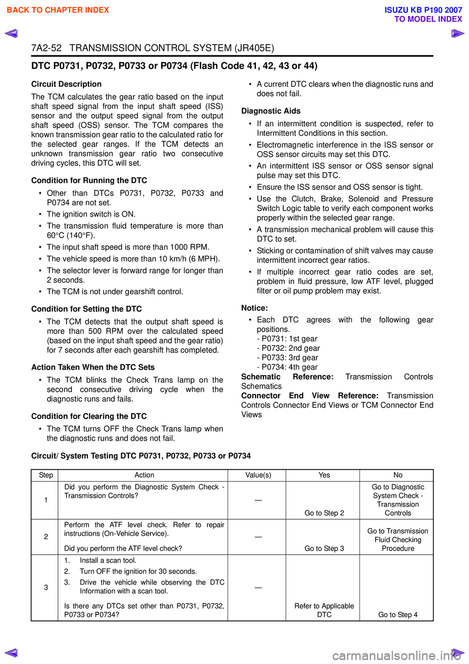
DTC P0731, P0732, P0733 or P0734 (Flash Code 41, 42, 43 or 44)
Circuit Description
The TCM calculates the gear ratio based on the input
shaft speed signal from the input shaft speed (ISS)
sensor and the output speed signal from the output
shaft speed (OSS) sensor. The TCM compares the
known transmission gear ratio to the calculated ratio for
the selected gear ranges. If the TCM detects an
unknown transmission gear ratio two consecutive
driving cycles, this DTC will set.
Condition for Running the DTC • Other than DTCs P0731, P0732, P0733 and P0734 are not set.
• The ignition switch is ON.
• The transmission fluid temperature is more than 60 °C (140 °F).
• The input shaft speed is more than 1000 RPM.
• The vehicle speed is more than 10 km/h (6 MPH).
• The selector lever is forward range for longer than 2 seconds.
• The TCM is not under gearshift control.
Condition for Setting the DTC • The TCM detects that the output shaft speed is more than 500 RPM over the calculated speed
(based on the input shaft speed and the gear ratio)
for 7 seconds after each gearshift has completed.
Action Taken When the DTC Sets • The TCM blinks the Check Trans lamp on the second consecutive driving cycle when the
diagnostic runs and fails.
Condition for Clearing the DTC • The TCM turns OFF the Check Trans lamp when the diagnostic runs and does not fail. • A current DTC clears when the diagnostic runs and
does not fail.
Diagnostic Aids • If an intermittent condition is suspected, refer to Intermittent Conditions in this section.
• Electromagnetic interference in the ISS sensor or OSS sensor circuits may set this DTC.
• An intermittent ISS sensor or OSS sensor signal pulse may set this DTC.
• Ensure the ISS sensor and OSS sensor is tight.
• Use the Clutch, Brake, Solenoid and Pressure Switch Logic table to verify each component works
properly within the selected gear range.
• A transmission mechanical problem will cause this DTC to set.
• Sticking or contamination of shift valves may cause intermittent incorrect gear ratios.
• If multiple incorrect gear ratio codes are set, problem in fluid pressure, low ATF level, plugged
filter or oil pump problem may exist.
Notice: • Each DTC agrees with the following gear positions.
- P0731: 1st gear
- P0732: 2nd gear
- P0733: 3rd gear
- P0734: 4th gear
Schematic Reference: Transmission Controls
Schematics
Connector End View Reference: Transmission
Controls Connector End Views or TCM Connector End
Views
Circuit/ System Testing DTC P0731, P0732, P0733 or P0734
Step Action Value(s)Yes No
1 Did you perform the Diagnostic System Check -
Transmission Controls? —
Go to Step 2 Go to Diagnostic
System Check - Transmission Controls
2 Perform the ATF level check. Refer to repair
instructions (On-Vehicle Service).
Did you perform the ATF level check? —
Go to Step 3 Go to Transmission
Fluid Checking Procedure
3 1. Install a scan tool.
2. Turn OFF the ignition for 30 seconds.
3. Drive the vehicle while observing the DTC Information with a scan tool.
Is there any DTCs set other than P0731, P0732,
P0733 or P0734? —
Refer to Applicable DTC Go to Step 4
BACK TO CHAPTER INDEX
TO MODEL INDEX
ISUZU KB P190 2007
Page 4401 of 6020
TRANSMISSION CONTROL SYSTEM (JR405E) 7A2-117
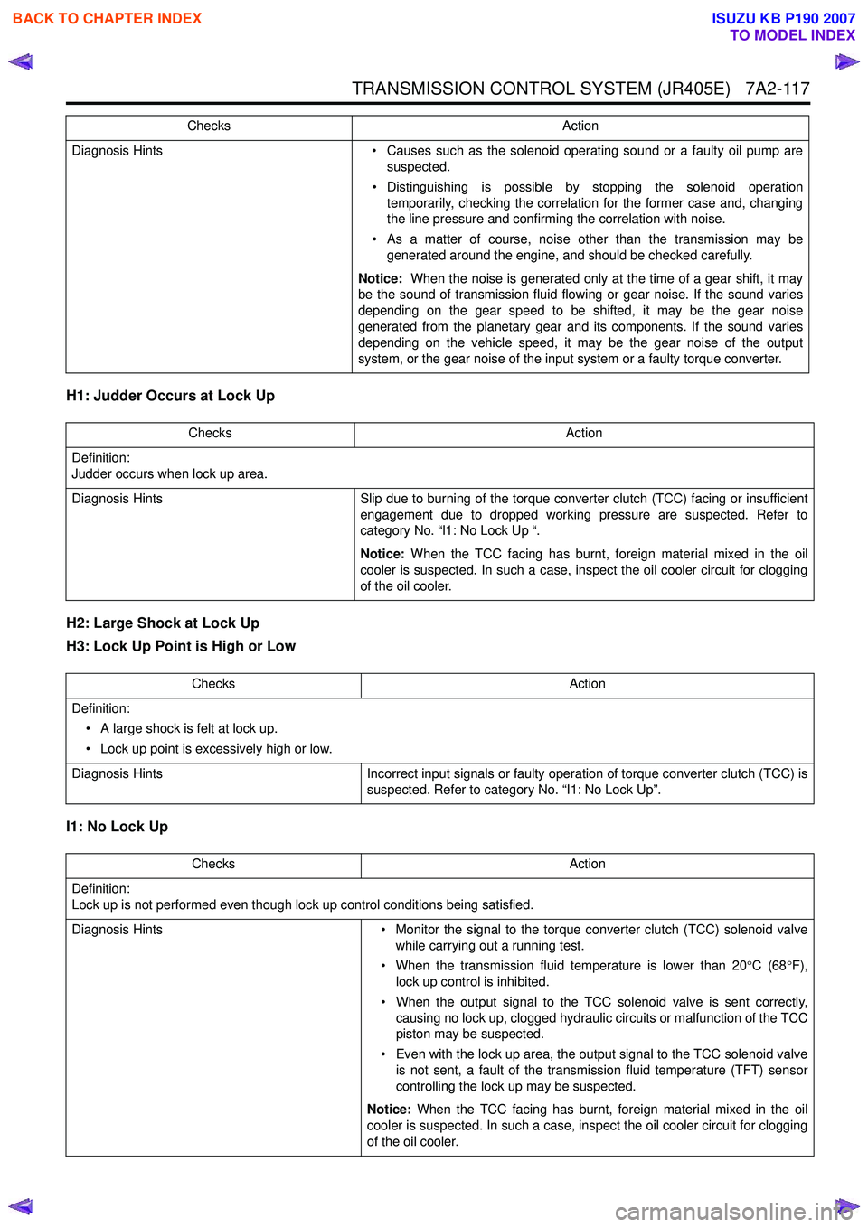
H1: Judder Occurs at Lock Up
H2: Large Shock at Lock Up
H3: Lock Up Point is High or Low
I1: No Lock Up
Diagnosis Hints • Causes such as the solenoid operating sound or a faulty oil pump are
suspected.
• Distinguishing is possible by stopping the solenoid operation temporarily, checking the correlation for the former case and, changing
the line pressure and confirming the correlation with noise.
• As a matter of course, noise other than the transmission may be generated around the engine, and should be checked carefully.
Notice: When the noise is generated only at the time of a gear shift, it may
be the sound of transmission fluid flowing or gear noise. If the sound varies
depending on the gear speed to be shifted, it may be the gear noise
generated from the planetary gear and its components. If the sound varies
depending on the vehicle speed, it may be the gear noise of the output
system, or the gear noise of the input system or a faulty torque converter.
Checks
Action
Checks Action
Definition:
Judder occurs when lock up area.
Diagnosis Hints Slip due to burning of the torque converter clutch (TCC) facing or insufficient
engagement due to dropped working pressure are suspected. Refer to
category No. “l1: No Lock Up “.
Notice: When the TCC facing has burnt, foreign material mixed in the oil
cooler is suspected. In such a case, inspect the oil cooler circuit for clogging
of the oil cooler.
Checks Action
Definition: • A large shock is felt at lock up.
• Lock up point is excessively high or low.
Diagnosis Hints Incorrect input signals or faulty operation of torque converter clutch (TCC) is
suspected. Refer to category No. “I1: No Lock Up”.
Checks Action
Definition:
Lock up is not performed even though lock up control conditions being satisfied.
Diagnosis Hints • Monitor the signal to the torque converter clutch (TCC) solenoid valve
while carrying out a running test.
• When the transmission fluid temperature is lower than 20 °C (68 °F),
lock up control is inhibited.
• When the output signal to the TCC solenoid valve is sent correctly, causing no lock up, clogged hydraulic circuits or malfunction of the TCC
piston may be suspected.
• Even with the lock up area, the output signal to the TCC solenoid valve is not sent, a fault of the transmission fluid temperature (TFT) sensor
controlling the lock up may be suspected.
Notice: When the TCC facing has burnt, foreign material mixed in the oil
cooler is suspected. In such a case, inspect the oil cooler circuit for clogging
of the oil cooler.
BACK TO CHAPTER INDEX
TO MODEL INDEX
ISUZU KB P190 2007