2007 ISUZU KB P190 Wiring harness
[x] Cancel search: Wiring harnessPage 4076 of 6020
7A2-110 TRANSMISSION CONTROL SYSTEM (AW30–40LE)
Conditions For Clearing The DTC
• The DTC can be cleared from the TCM history by
using a scan tool.
• The DTC will be cleared from history when the vehicle has achieved 40 warm-up cycles without a
failure reported.
•
After more than 1 second has elapsed after the
ignition key has been turned “ON”, short between
No.11 and No.4 (ground) of DLC (Data Link
Connector). Then, after 1 second, but within 6
seconds, discontinue shorting.
Diagnostic Aids
• Inspect the wiring for poor electrical connection at the
TCM. Look for possible bent, backed out, deformed
or damaged terminals. Check for weak terminal
tension as well. Also check for a chafed wire that
could short to bare metal or other wiring. Inspect for a
broken wire inside the insulation.
• W hen diagnosing for a possible intermittent short o
r
open condition, move the wiring harness while
observing test equipment for a change.
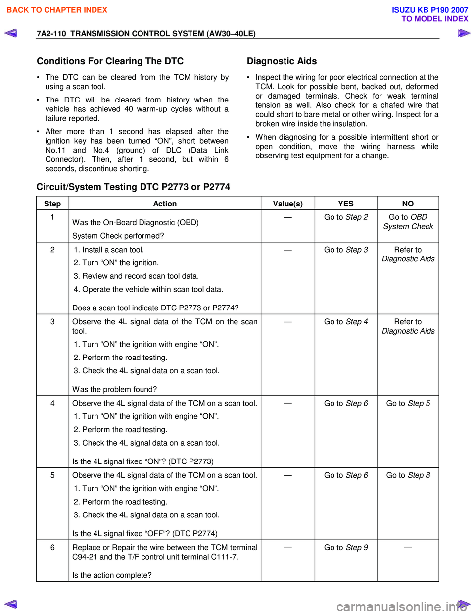
Circuit/System Testing DTC P2773 or P2774
Step Action Value(s) YES NO
1
W as the On-Board Diagnostic (OBD)
System Check performed? — Go to
Step 2 Go to OBD
System Check
2 1. Install a scan tool.
2. Turn “ON” the ignition.
3. Review and record scan tool data.
4. Operate the vehicle within scan tool data.
Does a scan tool indicate DTC P2773 or P2774? — Go to
Step 3 Refer to
Diagnostic Aids
3 Observe the 4L signal data of the TCM on the scan tool.
1. Turn “ON” the ignition with engine “ON”.
2. Perform the road testing.
3. Check the 4L signal data on a scan tool.
W as the problem found? — Go to
Step 4 Refer to
Diagnostic Aids
4 Observe the 4L signal data of the TCM on a scan tool.
1. Turn “ON” the ignition with engine “ON”.
2. Perform the road testing.
3. Check the 4L signal data on a scan tool.
Is the 4L signal fixed “ON”? (DTC P2773) — Go to
Step 6 Go to Step 5
5 Observe the 4L signal data of the TCM on a scan tool.
1. Turn “ON” the ignition with engine “ON”.
2. Perform the road testing.
3. Check the 4L signal data on a scan tool.
Is the 4L signal fixed “OFF”? (DTC P2774) — Go to
Step 6 Go to Step 8
6 Replace or Repair the wire between the TCM terminal
C94-21 and the T/F control unit terminal C111-7.
Is the action complete? — Go to
Step 9 —
BACK TO CHAPTER INDEX
TO MODEL INDEX
ISUZU KB P190 2007
Page 4079 of 6020
TRANSMISSION CONTROL SYSTEM (AW30–40LE) 7A2-113
(2) All of the following conditions are met.
• Device Control is not operating.
• Disable Normal Communication is receiving
enable.
• DTC Clear is not operating.
The following condition at ignition “OFF” form “ON” is
detected seven times in total in 1 cycle.
• Receiving BUS “OFF” information from CAN
controller.
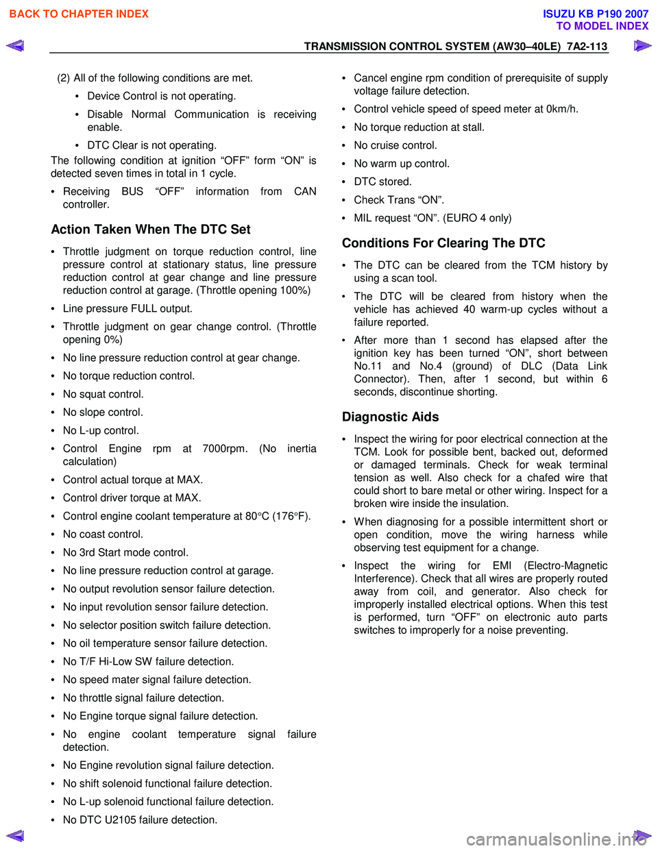
Action Taken When The DTC Set
• Throttle judgment on torque reduction control, line
pressure control at stationary status, line pressure
reduction control at gear change and line pressure
reduction control at garage. (Throttle opening 100%)
• Line pressure FULL output.
• Throttle judgment on gear change control. (Throttle
opening 0%)
• No line pressure reduction control at gear change.
• No torque reduction control.
• No squat control.
• No slope control.
• No L-up control.
• Control Engine rpm at 7000rpm. (No inertia
calculation)
• Control actual torque at MAX.
• Control driver torque at MAX.
• Control engine coolant temperature at 80 °C (176 °F).
• No coast control.
• No 3rd Start mode control.
• No line pressure reduction control at garage.
• No output revolution sensor failure detection.
• No input revolution sensor failure detection.
• No selector position switch failure detection.
• No oil temperature sensor failure detection.
• No T/F Hi-Low SW failure detection.
• No speed mater signal failure detection.
• No throttle signal failure detection.
• No Engine torque signal failure detection.
• No engine coolant temperature signal failure
detection.
• No Engine revolution signal failure detection.
• No shift solenoid functional failure detection.
• No L-up solenoid functional failure detection.
• No DTC U2105 failure detection.
• Cancel engine rpm condition of prerequisite of suppl
y
voltage failure detection.
• Control vehicle speed of speed meter at 0km/h.
• No torque reduction at stall.
• No cruise control.
• No warm up control.
• DTC stored.
• Check Trans “ON”.
• MIL request “ON”. (EURO 4 only)
Conditions For Clearing The DTC
• The DTC can be cleared from the TCM history by
using a scan tool.
• The DTC will be cleared from history when the vehicle has achieved 40 warm-up cycles without a
failure reported.
•
After more than 1 second has elapsed after the
ignition key has been turned “ON”, short between
No.11 and No.4 (ground) of DLC (Data Link
Connector). Then, after 1 second, but within 6
seconds, discontinue shorting.
Diagnostic Aids
• Inspect the wiring for poor electrical connection at the
TCM. Look for possible bent, backed out, deformed
or damaged terminals. Check for weak terminal
tension as well. Also check for a chafed wire that
could short to bare metal or other wiring. Inspect for a
broken wire inside the insulation.
• W hen diagnosing for a possible intermittent short o
r
open condition, move the wiring harness while
observing test equipment for a change.
• Inspect the wiring for EMI (Electro-Magnetic
Interference). Check that all wires are properly routed
away from coil, and generator. Also check fo
r
improperly installed electrical options. W hen this test
is performed, turn “OFF” on electronic auto parts
switches to improperly for a noise preventing.
BACK TO CHAPTER INDEX
TO MODEL INDEX
ISUZU KB P190 2007
Page 4083 of 6020
TRANSMISSION CONTROL SYSTEM (AW30–40LE) 7A2-117
(3) All of the following conditions are met.
• Device Control is not operating.
• Disable Normal Communication is receiving
enable.
• DTC Clear is not operating.
(4) DTC U2104 is not detecting failure or not deciding failure.
Condition For Setting The DTC
Detection standard is met for 2.5 second continuously.
Detection standard:
If one or more ID sent from Engine Control Module
(ECM) is not completed receiving for 2 basic cycles
since last receiving completion.
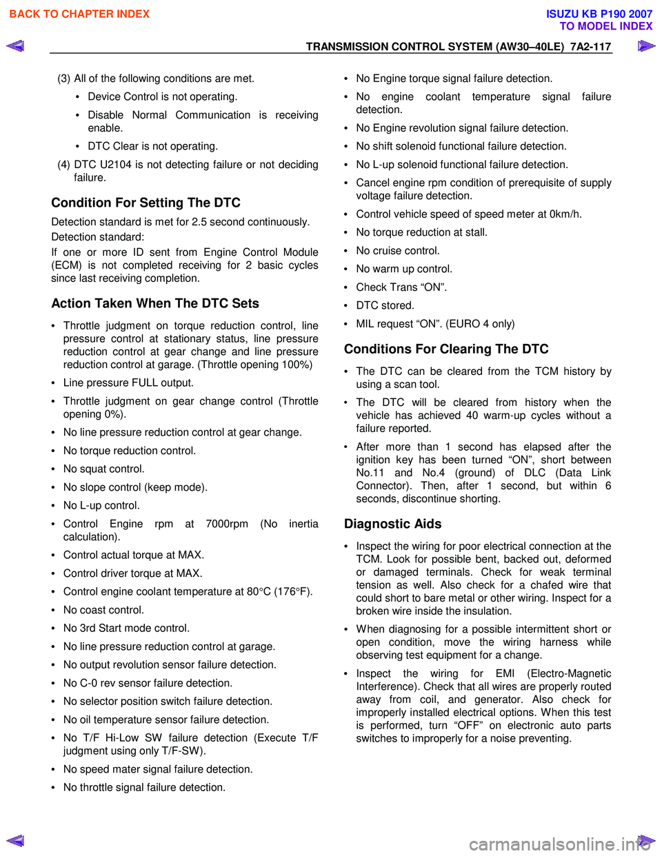
Action Taken When The DTC Sets
• Throttle judgment on torque reduction control, line
pressure control at stationary status, line pressure
reduction control at gear change and line pressure
reduction control at garage. (Throttle opening 100%)
• Line pressure FULL output.
• Throttle judgment on gear change control (Throttle
opening 0%).
• No line pressure reduction control at gear change.
• No torque reduction control.
• No squat control.
• No slope control (keep mode).
• No L-up control.
• Control Engine rpm at 7000rpm (No inertia
calculation).
• Control actual torque at MAX.
• Control driver torque at MAX.
• Control engine coolant temperature at 80 °C (176 °F).
• No coast control.
• No 3rd Start mode control.
• No line pressure reduction control at garage.
• No output revolution sensor failure detection.
• No C-0 rev sensor failure detection.
• No selector position switch failure detection.
• No oil temperature sensor failure detection.
• No T/F Hi-Low SW failure detection (Execute T/F
judgment using only T/F-SW ).
• No speed mater signal failure detection.
• No throttle signal failure detection.
• No Engine torque signal failure detection.
• No engine coolant temperature signal failure
detection.
• No Engine revolution signal failure detection.
• No shift solenoid functional failure detection.
• No L-up solenoid functional failure detection.
• Cancel engine rpm condition of prerequisite of suppl
y
voltage failure detection.
• Control vehicle speed of speed meter at 0km/h.
• No torque reduction at stall.
• No cruise control.
• No warm up control.
• Check Trans “ON”.
• DTC stored.
• MIL request “ON”. (EURO 4 only)
Conditions For Clearing The DTC
• The DTC can be cleared from the TCM history by
using a scan tool.
• The DTC will be cleared from history when the vehicle has achieved 40 warm-up cycles without a
failure reported.
• After more than 1 second has elapsed after the ignition key has been turned “ON”, short between
No.11 and No.4 (ground) of DLC (Data Link
Connector). Then, after 1 second, but within 6
seconds, discontinue shorting.
Diagnostic Aids
• Inspect the wiring for poor electrical connection at the
TCM. Look for possible bent, backed out, deformed
or damaged terminals. Check for weak terminal
tension as well. Also check for a chafed wire that
could short to bare metal or other wiring. Inspect for a
broken wire inside the insulation.
• W hen diagnosing for a possible intermittent short o
r
open condition, move the wiring harness while
observing test equipment for a change.
• Inspect the wiring for EMI (Electro-Magnetic
Interference). Check that all wires are properly routed
away from coil, and generator. Also check fo
r
improperly installed electrical options. W hen this test
is performed, turn “OFF” on electronic auto parts
switches to improperly for a noise preventing.
BACK TO CHAPTER INDEX
TO MODEL INDEX
ISUZU KB P190 2007
Page 4120 of 6020
ON-VEHICLE SERVICE (AW30–40LE) 7A3-35
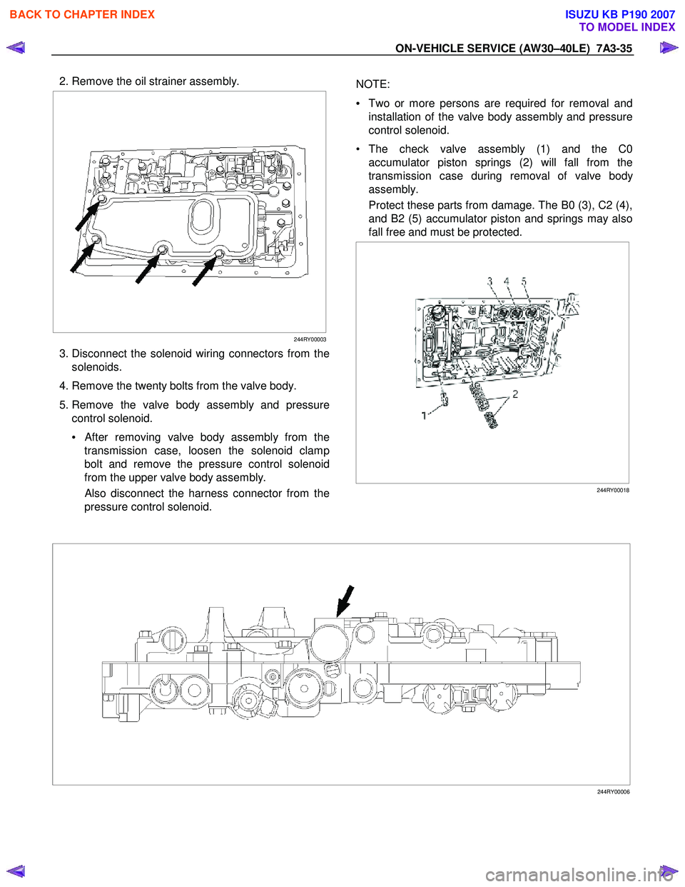
2. Remove the oil strainer assembly.
244RY00003
3. Disconnect the solenoid wiring connectors from the
solenoids.
4. Remove the twenty bolts from the valve body.
5. Remove the valve body assembly and pressure control solenoid.
•
After removing valve body assembly from the
transmission case, loosen the solenoid clamp
bolt and remove the pressure control solenoid
from the upper valve body assembly.
Also disconnect the harness connector from the
pressure control solenoid.
NOTE:
• Two or more persons are required for removal and
installation of the valve body assembly and pressure
control solenoid.
• The check valve assembly (1) and the C0 accumulator piston springs (2) will fall from the
transmission case during removal of valve bod
y
assembly.
Protect these parts from damage. The B0 (3), C2 (4),
and B2 (5) accumulator piston and springs may also
fall free and must be protected.
244RY00018
244RY00006
BACK TO CHAPTER INDEX
TO MODEL INDEX
ISUZU KB P190 2007
Page 4337 of 6020
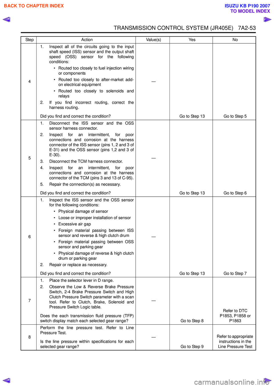
TRANSMISSION CONTROL SYSTEM (JR405E) 7A2-53
41. Inspect all of the circuits going to the input
shaft speed (ISS) sensor and the output shaft
speed (OSS) sensor for the following
conditions:
• Routed too closely to fuel injection wiring or components
• Routed too closely to after-market add- on electrical equipment
• Routed too closely to solenoids and relays
2. If you find incorrect routing, correct the harness routing.
Did you find and correct the condition? —
Go to Step 13 Go to Step 5
5 1. Disconnect the ISS sensor and the OSS
sensor harness connector.
2. Inspect for an intermittent, for poor connections and corrosion at the harness
connector of the ISS sensor (pins 1, 2 and 3 of
E-31) and the OSS sensor (pins 1,2 and 3 of
E-30).
3. Disconnect the TCM harness connector.
4. Inspect for an intermittent, for poor connections and corrosion at the harness
connector of the TCM (pins 3 and 13 of C-95).
5. Repair the connection(s) as necessary.
Did you find and correct the condition? —
Go to Step 13 Go to Step 6
6 1. Inspect the ISS sensor and the OSS sensor
for the following conditions:
• Physical damage of sensor
• Loose or improper installation of sensor
• Excessive air gap
• Foreign material passing between ISS sensor and reverse & high clutch drum
• Foreign material passing between OSS sensor and parking gear
• Physical damage of reverse & high clutch drum or parking gear
2. Repair or replace as necessary.
Did you find and correct the condition? —
Go to Step 13 Go to Step 7
7 1. Place the selector lever in D range.
2. Observe the Low & Reverse Brake Pressure Switch, 2-4 Brake Pressure Switch and High
Clutch Pressure Switch parameter with a scan
tool. Refer to Clutch, Brake, Solenoid and
Pressure Switch Logic table.
Does the each transmission fluid pressure (TFP)
switch display match each selected gear range? —
Go to Step 8 Refer to DTC
P1853, P1858 or P1863
8 Perform the line pressure test. Refer to Line
Pressure Test.
Is the line pressure within specifications for each
selected gear range? —
Go to Step 9 Refer to appropriate
instructions in the
Line Pressure Test
Step
Action Value(s)Yes No
BACK TO CHAPTER INDEX
TO MODEL INDEX
ISUZU KB P190 2007
Page 4376 of 6020
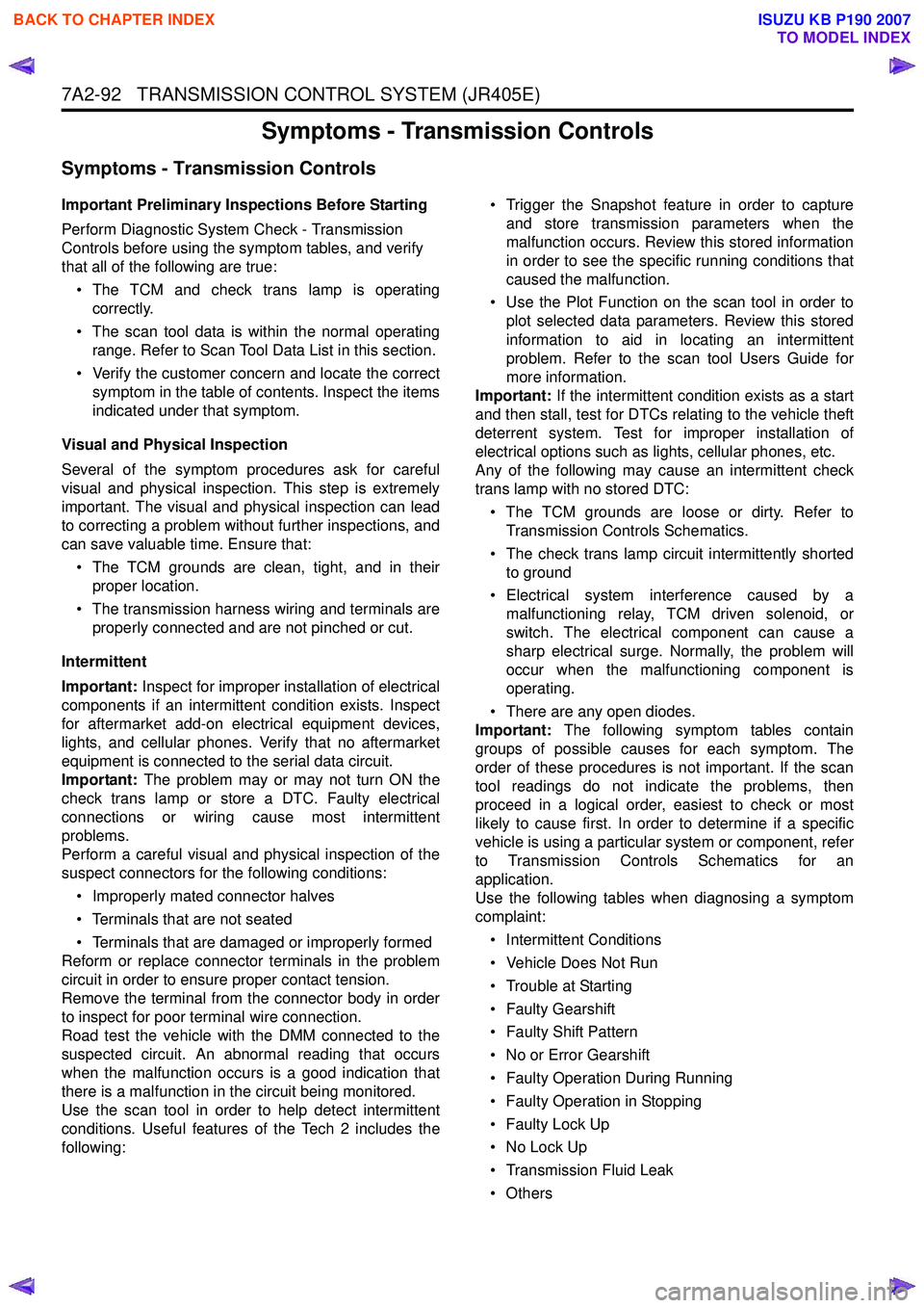
7A2-92 TRANSMISSION CONTROL SYSTEM (JR405E)
Symptoms - Transmission Controls
Symptoms - Transmission Controls
Important Preliminary Inspections Before Starting
Perform Diagnostic System Check - Transmission
Controls before using the symptom tables, and verify
that all of the following are true:
• The TCM and check trans lamp is operating correctly.
• The scan tool data is within the normal operating range. Refer to Scan Tool Data List in this section.
• Verify the customer concern and locate the correct symptom in the table of contents. Inspect the items
indicated under that symptom.
Visual and Physical Inspection
Several of the symptom procedures ask for careful
visual and physical inspection. This step is extremely
important. The visual and physical inspection can lead
to correcting a problem without further inspections, and
can save valuable time. Ensure that:
• The TCM grounds are clean, tight, and in their proper location.
• The transmission harness wiring and terminals are properly connected and are not pinched or cut.
Intermittent
Important: Inspect for improper installation of electrical
components if an intermittent condition exists. Inspect
for aftermarket add-on electrical equipment devices,
lights, and cellular phones. Verify that no aftermarket
equipment is connected to the serial data circuit.
Important: The problem may or may not turn ON the
check trans lamp or store a DTC. Faulty electrical
connections or wiring cause most intermittent
problems.
Perform a careful visual and physical inspection of the
suspect connectors for the following conditions:
• Improperly mated connector halves
• Terminals that are not seated
• Terminals that are damaged or improperly formed
Reform or replace connector terminals in the problem
circuit in order to ensure proper contact tension.
Remove the terminal from the connector body in order
to inspect for poor terminal wire connection.
Road test the vehicle with the DMM connected to the
suspected circuit. An abnormal reading that occurs
when the malfunction occurs is a good indication that
there is a malfunction in the circuit being monitored.
Use the scan tool in order to help detect intermittent
conditions. Useful features of the Tech 2 includes the
following: • Trigger the Snapshot feature in order to capture
and store transmission parameters when the
malfunction occurs. Review this stored information
in order to see the specific running conditions that
caused the malfunction.
• Use the Plot Function on the scan tool in order to plot selected data parameters. Review this stored
information to aid in locating an intermittent
problem. Refer to the scan tool Users Guide for
more information.
Important: If the intermittent condition exists as a start
and then stall, test for DTCs relating to the vehicle theft
deterrent system. Test for improper installation of
electrical options such as lights, cellular phones, etc.
Any of the following may cause an intermittent check
trans lamp with no stored DTC:
• The TCM grounds are loose or dirty. Refer to Transmission Controls Schematics.
• The check trans lamp circuit intermittently shorted to ground
• Electrical system interference caused by a malfunctioning relay, TCM driven solenoid, or
switch. The electrical component can cause a
sharp electrical surge. Normally, the problem will
occur when the malfunctioning component is
operating.
• There are any open diodes.
Important: The following symptom tables contain
groups of possible causes for each symptom. The
order of these procedures is not important. If the scan
tool readings do not indicate the problems, then
proceed in a logical order, easiest to check or most
likely to cause first. In order to determine if a specific
vehicle is using a particular system or component, refer
to Transmission Controls Schematics for an
application.
Use the following tables when diagnosing a symptom
complaint:
• Intermittent Conditions
• Vehicle Does Not Run
• Trouble at Starting
• Faulty Gearshift
• Faulty Shift Pattern
• No or Error Gearshift
• Faulty Operation During Running
• Faulty Operation in Stopping
• Faulty Lock Up
• No Lock Up
• Transmission Fluid Leak
•Others
BACK TO CHAPTER INDEX
TO MODEL INDEX
ISUZU KB P190 2007
Page 4377 of 6020
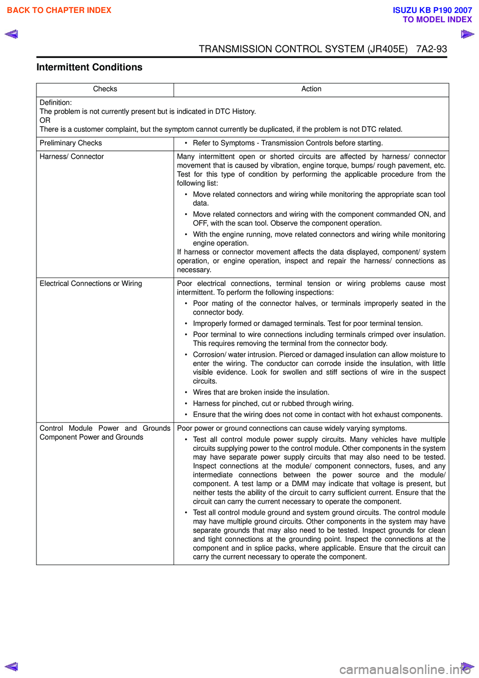
TRANSMISSION CONTROL SYSTEM (JR405E) 7A2-93
Intermittent Conditions
ChecksAction
Definition:
The problem is not currently present but is indicated in DTC History.
OR
There is a customer complaint, but the symptom cannot currently be duplicated, if the problem is not DTC related.
Preliminary Checks • Refer to Symptoms - Transmission Controls before starting.
Harness/ Connector Many intermittent open or shorted circuits are affected by harness/ connector
movement that is caused by vibration, engine torque, bumps/ rough pavement, etc.
Test for this type of condition by performing the applicable procedure from the
following list:
• Move related connectors and wiring while monitoring the appropriate scan tool data.
• Move related connectors and wiring with the component commanded ON, and OFF, with the scan tool. Observe the component operation.
• With the engine running, move related connectors and wiring while monitoring engine operation.
If harness or connector movement affects the data displayed, component/ system
operation, or engine operation, inspect and repair the harness/ connections as
necessary.
Electrical Connections or Wiring Poor electrical connections, terminal tension or wiring problems cause most intermittent. To perform the following inspections:
• Poor mating of the connector halves, or terminals improperly seated in the connector body.
• Improperly formed or damaged terminals. Test for poor terminal tension.
• Poor terminal to wire connections including terminals crimped over insulation. This requires removing the terminal from the connector body.
• Corrosion/ water intrusion. Pierced or damaged insulation can allow moisture to enter the wiring. The conductor can corrode inside the insulation, with little
visible evidence. Look for swollen and stiff sections of wire in the suspect
circuits.
• Wires that are broken inside the insulation.
• Harness for pinched, cut or rubbed through wiring.
• Ensure that the wiring does not come in contact with hot exhaust components.
Control Module Power and Grounds
Component Power and Grounds Poor power or ground connections can cause widely varying symptoms.
• Test all control module power supply circuits. Many vehicles have multiple circuits supplying power to the control module. Other components in the system
may have separate power supply circuits that may also need to be tested.
Inspect connections at the module/ component connectors, fuses, and any
intermediate connections between the power source and the module/
component. A test lamp or a DMM may indicate that voltage is present, but
neither tests the ability of the circuit to carry sufficient current. Ensure that the
circuit can carry the current necessary to operate the component.
• Test all control module ground and system ground circuits. The control module may have multiple ground circuits. Other components in the system may have
separate grounds that may also need to be tested. Inspect grounds for clean
and tight connections at the grounding point. Inspect the connections at the
component and in splice packs, where applicable. Ensure that the circuit can
carry the current necessary to operate the component.
BACK TO CHAPTER INDEX
TO MODEL INDEX
ISUZU KB P190 2007
Page 4885 of 6020
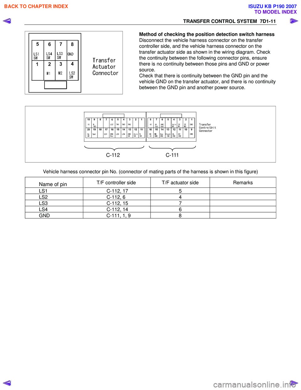
TRANSFER CONTROL SYSTEM 7D1-11
Method of checking the position detection switch harness
Disconnect the vehicle harness connector on the transfer
controller side, and the vehicle harness connector on the
transfer actuator side as shown in the wiring diagram. Check
the continuity between the following connector pins, ensure
there is no continuity between those pins and GND or power
source.
Check that there is continuity between the GND pin and the
vehicle GND on the transfer actuator, and there is no continuity
between the GND pin and another power source.
C-112 C-111
Vehicle harness connector pin No. (connector of mating parts of the harness is shown in this figure)
Name of pin T/F controller side T/F actuator side Remarks
LS1 C-112, 17 5
LS2 C-112, 6 4
LS3 C-112, 15 7
LS4 C-112, 14 6
GND C-111, 1, 9 8
BACK TO CHAPTER INDEX
TO MODEL INDEX
ISUZU KB P190 2007