2007 ISUZU KB P190 Wiring harness
[x] Cancel search: Wiring harnessPage 3902 of 6020
Automatic Transmission – 4L60E – Electrical Diagnosis Page 7C2–116
• At the time of the second failure, the ECM records the operating conditions when the conditions for setting the DTC
are met. The ECM stores this information as a Freeze Frame.
• The TCM stores DTC P2769 in TCM history during the second consecutive trip in which the conditions for setting
the DTC are met.
Conditions for Clearing the DTC
• The ECM turns off the MIL after the fourth consecutive drive trip in which the TCM does not send a MIL illumination
request.
• Tech 2 can clear the DTC.
• The TCM clears the DTC from TCM history if the vehicle completes 40 warm-up cycles without a non-emission
related diagnostic fault occurring.
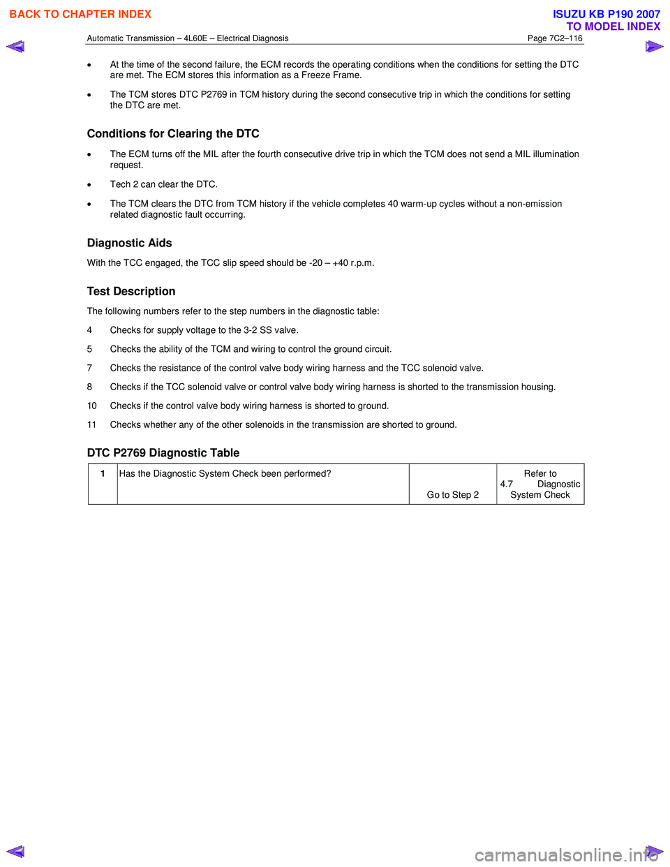
Diagnostic Aids
W ith the TCC engaged, the TCC slip speed should be -20 – +40 r.p.m.
Test Description
The following numbers refer to the step numbers in the diagnostic table:
4 Checks for supply voltage to the 3-2 SS valve.
5 Checks the ability of the TCM and wiring to control the ground circuit.
7 Checks the resistance of the control valve body wiring harness and the TCC solenoid valve.
8 Checks if the TCC solenoid valve or control valve body wiring harness is shorted to the transmission housing.
10 Checks if the control valve body wiring harness is shorted to ground.
11 Checks whether any of the other solenoids in the transmission are shorted to ground.
DTC P2769 Diagnostic Table
1 Has the Diagnostic System Check been performed?
Go to Step 2 Refer to
4.7 Diagnostic System Check
BACK TO CHAPTER INDEX
TO MODEL INDEX
ISUZU KB P190 2007
Page 3904 of 6020
Automatic Transmission – 4L60E – Electrical Diagnosis Page 7C2–118
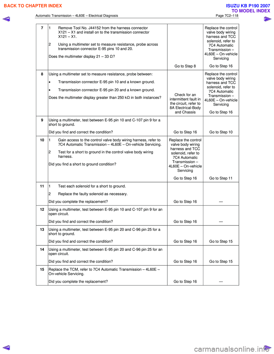
7 1 Remove Tool No. J44152 from the harness connector
X121 – X1 and install on to the transmission connector
X121 – X1.
2 Using a multimeter set to measure resistance, probe across transmission connector E-95 pins 10 and 20.
Does the multimeter display 21 – 33 Ω?
Go to Step 8 Replace the control
valve body wiring
harness and TCC
solenoid, refer to 7C4 Automatic
Transmission –
4L60E – On-vehicle
Servicing
Go to Step 16
8 Using a multimeter set to measure resistance, probe between:
• Transmission connector E-95 pin 10 and a known ground.
• Transmission connector E-95 pin 20 and a known ground.
Does the multimeter display greater than 250 k Ω in both instances? Check for an
intermittent fault in the circuit, refer to
8A Electrical-Body
and Chassis Replace the control
valve body wiring
harness and TCC solenoid, refer to
7C4 Automatic
Transmission –
4L60E – On-vehicle Servicing
Go to Step 16
9 Using a multimeter, test between E-95 pin 10 and C-107 pin 9 for a
short to ground.
Did you find and correct the condition? Go to Step 16 Go to Step 10
10 1 Gain access to the control valve body wiring harness, refer to
7C4 Automatic Transmission – 4L60E – On-vehicle Servicing.
2 Test for a short to ground in the control valve body wiring harness.
Did you find a short to ground condition? Replace the control
valve body wiring
harness and TCC solenoid, refer to
7C4 Automatic
Transmission –
4L60E – On-vehicle Servicing
Go to Step 16 Go to Step 11
11 1 Test each solenoid for a short to ground.
2 Replace the faulty solenoid as necessary.
Did you complete the replacement? Go to Step 16 —
12 Using a multimeter, test between E-95 pin 10 and C-107 pin 9 for an
open circuit.
Did you find and correct the condition? Go to Step 16 —
13 Using a multimeter, test between E-95 pin 20 and C-96 pin 25 for a
short to ground.
Did you find and correct the condition? Go to Step 16 Go to Step 15
14 Using a multimeter, test between E-95 pin 20 and C-96 pin 25 for an
open circuit.
Did you find and correct the condition? Go to Step 16 Go to Step 15
15 Replace the TCM, refer to 7C4 Automatic Transmission – 4L60E –
On-vehicle Servicing.
Did you complete the replacement? Go to Step 16 —
BACK TO CHAPTER INDEX
TO MODEL INDEX
ISUZU KB P190 2007
Page 3905 of 6020
Automatic Transmission – 4L60E – Electrical Diagnosis Page 7C2–119
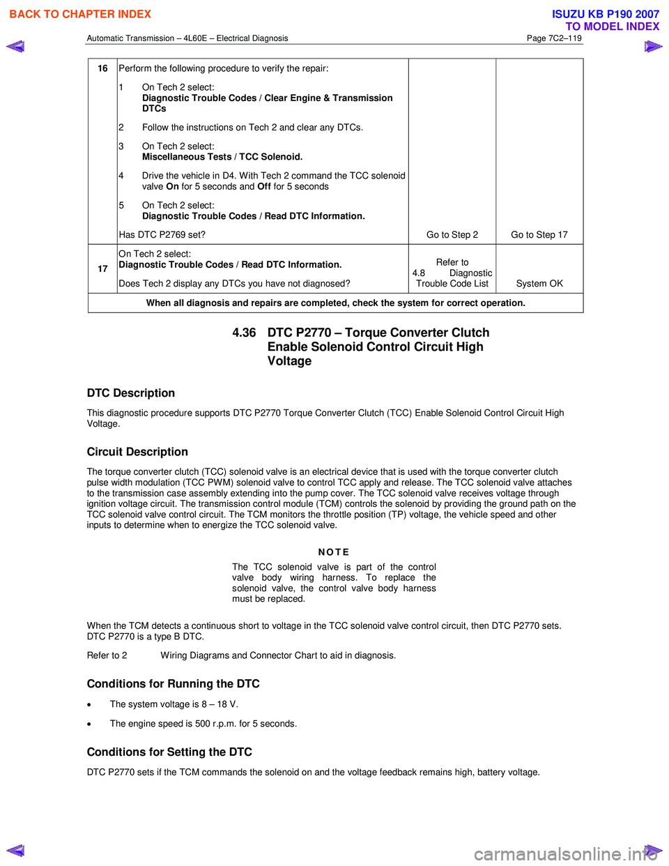
16 Perform the following procedure to verify the repair:
1 On Tech 2 select: Diagnostic Trouble Codes / Clear Engine & Transmission
DTCs
2 Follow the instructions on Tech 2 and clear any DTCs.
3 On Tech 2 select: Miscellaneous Tests / TCC Solenoid.
4 Drive the vehicle in D4. With Tech 2 command the TCC solenoid valve On for 5 seconds and Off for 5 seconds
5 On Tech 2 select:
Diagnostic Trouble Codes / Read DTC Information.
Has DTC P2769 set? Go to Step 2 Go to Step 17
17 On Tech 2 select:
Diagnostic Trouble Codes / Read DTC Information.
Does Tech 2 display any DTCs you have not diagnosed? Refer to
4.8 Diagnostic Trouble Code List System OK
When all diagnosis and repairs are completed, check the
system for correct operation.
4.36 DTC P2770 – Torque Converter Clutch
Enable Solenoid Control Circuit High
Voltage
DTC Description
This diagnostic procedure supports DTC P2770 Torque Converter Clutch (TCC) Enable Solenoid Control Circuit High
Voltage.
Circuit Description
The torque converter clutch (TCC) solenoid valve is an electrical device that is used with the torque converter clutch
pulse width modulation (TCC PWM) solenoid valve to control TCC apply and release. The TCC solenoid valve attaches
to the transmission case assembly extending into the pump cover. The TCC solenoid valve receives voltage through
ignition voltage circuit. The transmission control module (TCM) controls the solenoid by providing the ground path on the
TCC solenoid valve control circuit. The TCM monitors the throttle position (TP) voltage, the vehicle speed and other
inputs to determine when to energize the TCC solenoid valve.
NOTE
The TCC solenoid valve is part of the control
valve body wiring harness. To replace the
solenoid valve, the control valve body harness
must be replaced.
W hen the TCM detects a continuous short to voltage in the TCC solenoid valve control circuit, then DTC P2770 sets.
DTC P2770 is a type B DTC.
Refer to 2 W iring Diagrams and Connector Chart to aid in diagnosis.
Conditions for Running the DTC
• The system voltage is 8 – 18 V.
• The engine speed is 500 r.p.m. for 5 seconds.
Conditions for Setting the DTC
DTC P2770 sets if the TCM commands the solenoid on and the voltage feedback remains high, battery voltage.
BACK TO CHAPTER INDEX
TO MODEL INDEX
ISUZU KB P190 2007
Page 3906 of 6020
Automatic Transmission – 4L60E – Electrical Diagnosis Page 7C2–120
Action Taken When the DTC Sets
• The TCM requests the ECM to illuminate the MIL during the second consecutive trip in which the conditions for
setting the DTC are met.
• The TCM commands maximum line pressure.
• The TCM freezes transmission adaptive functions.
• The TCM inhibits TCC engagement.
• The TCM inhibits 4th gear if in hot mode.
• At the time of the first failure, the TCM records the operating conditions when the conditions for setting the DTC are
met. The TCM stores this information as a Failure Record.
• At the time of the second failure, the ECM records the operating conditions when the conditions for setting the DTC
are met. The ECM stores this information as a Freeze Frame.
• The TCM stores DTC P2770 in TCM history during the second consecutive trip in which the conditions for setting
the DTC are met.
Conditions for Clearing the DTC
• The ECM turns off the MIL after the fourth consecutive drive trip in which the TCM does not send a MIL illumination
request.
• Tech 2 can clear the DTC.
• The TCM clears the DTC from TCM history if the vehicle completes 40 warm-up cycles without a non-emission
related diagnostic fault occurring.
• The TCM cancels the DTC default actions when the ignition is off long enough to power down the TCM.
Test Description
The following numbers refer to the step numbers in the diagnostic table:
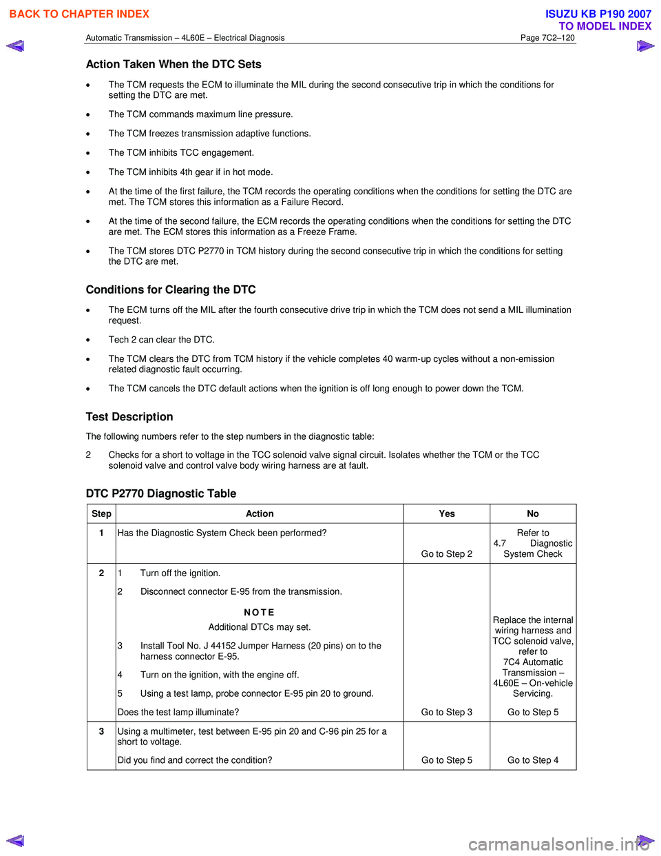
2 Checks for a short to voltage in the TCC solenoid valve signal circuit. Isolates whether the TCM or the TCC solenoid valve and control valve body wiring harness are at fault.
DTC P2770 Diagnostic Table
Step Action Yes No
1 Has the Diagnostic System Check been performed?
Go to Step 2 Refer to
4.7 Diagnostic System Check
2 1 Turn off the ignition.
2 Disconnect connector E-95 from the transmission.
NOTE
Additional DTCs may set.
3 Install Tool No. J 44152 Jumper Harness (20 pins) on to the harness connector E-95.
4 Turn on the ignition, with the engine off.
5 Using a test lamp, probe connector E-95 pin 20 to ground.
Does the test lamp illuminate? Go to Step 3 Replace the internal
wiring harness and
TCC solenoid valve, refer to
7C4 Automatic
Transmission –
4L60E – On-vehicle
Servicing.
Go to Step 5
3 Using a multimeter, test between E-95 pin 20 and C-96 pin 25 for a
short to voltage.
Did you find and correct the condition? Go to Step 5 Go to Step 4
BACK TO CHAPTER INDEX
TO MODEL INDEX
ISUZU KB P190 2007
Page 3959 of 6020
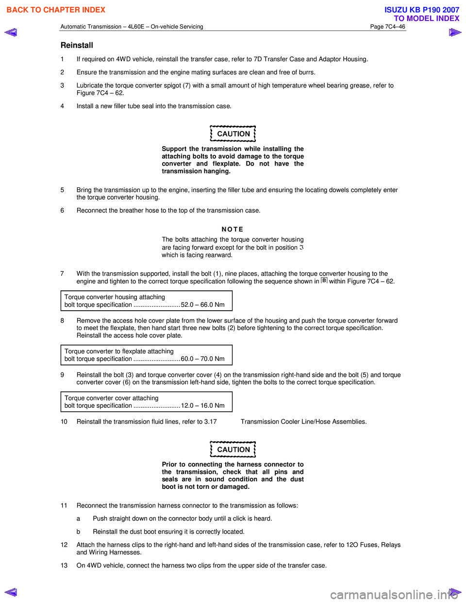
Automatic Transmission – 4L60E – On-vehicle Servicing Page 7C4–46
Reinstall
1 If required on 4W D vehicle, reinstall the transfer case, refer to 7D Transfer Case and Adaptor Housing.
2 Ensure the transmission and the engine mating surfaces are clean and free of burrs.
3 Lubricate the torque converter spigot (7) with a small amount of high temperature wheel bearing grease, refer to Figure 7C4 – 62.
4 Install a new filler tube seal into the transmission case.
Support the transmission while installing the
attaching bolts to avoid damage to the torque
converter and flexplate. Do not have the
transmission hanging.
5 Bring the transmission up to the engine, inserting the filler tube and ensuring the locating dowels completely enter the torque converter housing.
6 Reconnect the breather hose to the top of the transmission case.
NOTE
The bolts attaching the torque converter housing
are facing forward except for the bolt in position ℑ
which is facing rearward.
7 With the transmission supported, install the bolt (1), nine places, attaching the torque converter housing to the engine and tighten to the correct torque specification following the sequence shown in
within Figure 7C4 – 62.
Torque converter housing attaching
bolt torque specification .......................... 52.0 – 66.0 Nm
8 Remove the access hole cover plate from the lower surface of the housing and push the torque converter forward to meet the flexplate, then hand start three new bolts (2) before tightening to the correct torque specification.
Reinstall the access hole cover plate.
Torque converter to flexplate attaching
bolt torque specification .......................... 60.0 – 70.0 Nm
9 Reinstall the bolt (3) and torque converter cover (4) on the transmission right-hand side and the bolt (5) and torque converter cover (6) on the transmission left-hand side, tighten the bolts to the correct torque specification.
Torque converter cover attaching
bolt torque specification .......................... 12.0 – 16.0 Nm
10 Reinstall the transmission fluid lines, refer to 3.17 Transmission Cooler Line/Hose Assemblies.
Prior to connecting the harness connector to
the transmission, check that all pins and
seals are in sound condition and the dust
boot is not torn or damaged.
11 Reconnect the transmission harness connector to the transmission as follows: a Push straight down on the connector body until a click is heard.
b Reinstall the dust boot ensuring it is correctly located.
12 Attach the harness clips to the right-hand and left-hand sides of the transmission case, refer to 12O Fuses, Relays and Wiring Harnesses.
13 On 4WD vehicle, connect the harness two clips from the upper side of the transfer case.
BACK TO CHAPTER INDEX
TO MODEL INDEX
ISUZU KB P190 2007
Page 4007 of 6020
TRANSMISSION CONTROL SYSTEM (AW30–40LE) 7A2-41
• All of the following conditions are met.
- Device Control is not operating
- Disable Normal Communication Service is receiving enable
- DTC Clear is not operating
Condition For Setting The DTC
W hen the TCM detects following conditions at 20 times
continuously.
• Ignition voltage is less than 9 volts for 1 second o
r
more continuously. (DTC P0562)
• Ignition voltage is more than 18 volts for 1 second o
r
more continuously. (DTC P0563)
Action Taken When The DTC Sets
• DTC stored.
Conditions For Clearing The DTC
• The DTC can be cleared from the TCM history by
using a scan tool.
• The DTC will be cleared from history when the
vehicle has achieved 40 warm-up cycles without a
failure reported.
•
After more than 1 second has elapsed after the
ignition key has been turned “ON”, short between
No.11 and No.4 (ground) of DLC (Data Link
Connector). Then, after 1 second, but within 6
seconds, discontinue shorting.
Diagnostic Aids
•
Inspect the wiring for poor electrical connection at the
TCM. Look for possible bent, backed out, deformed
or damaged terminals. Check for weak terminal
tension as well. Also check for a chafed wire that
could short to bare metal or other wiring.
Inspect for a broken wire inside the insulation.
• W hen diagnosing for a possible intermittent short o
r
open condition, move the wiring harness while
observing test equipment for a change.
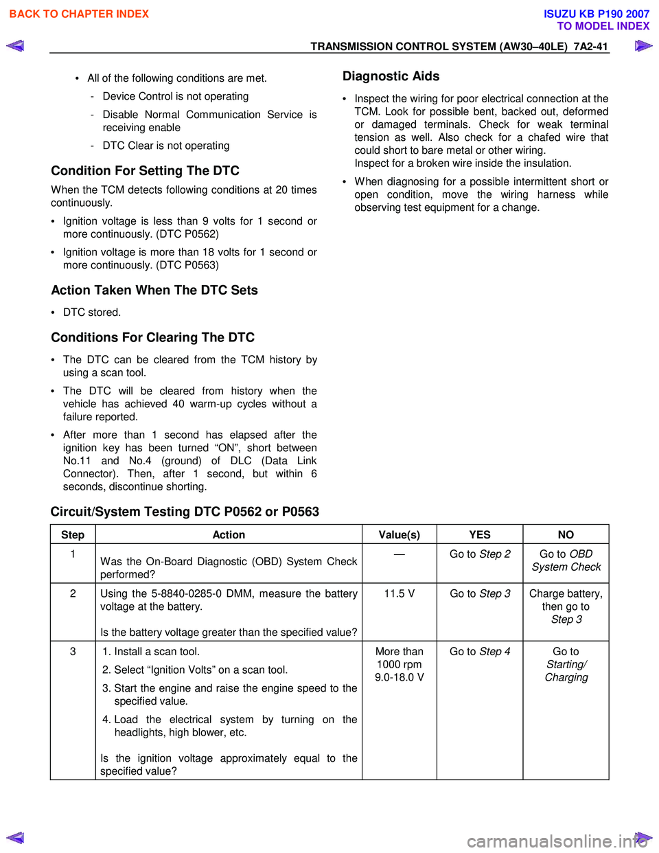
Circuit/System Testing DTC P0562 or P0563
Step Action Value(s) YES NO
1
W as the On-Board Diagnostic (OBD) System Check
performed? — Go to
Step 2 Go to OBD
System Check
2 Using the 5-8840-0285-0 DMM, measure the battery voltage at the battery.
Is the battery voltage greater than the specified value? 11.5 V Go to
Step 3 Charge battery,
then go to Step 3
3 1. Install a scan tool.
2. Select “Ignition Volts” on a scan tool.
3. Start the engine and raise the engine speed to the specified value.
4. Load the electrical system by turning on the headlights, high blower, etc.
Is the ignition voltage approximately equal to the
specified value? More than
1000 rpm
9.0-18.0 V Go to
Step 4 Go to
Starting/
Charging
BACK TO CHAPTER INDEX
TO MODEL INDEX
ISUZU KB P190 2007
Page 4012 of 6020
7A2-46 TRANSMISSION CONTROL SYSTEM (AW30–40LE)
(2) Not emergency mode.
(3) All of the following conditions are met. • Device Control is not operating.
• Disable Normal Communication service is
receiving enable.
• DTC Clear is not operating.
Condition For Setting The DTC
DTC P0707
All of the following conditions are met for 30 seconds or
more continuously.
• All of the switches are “OFF”.
• Output revolution is more than 30 km/h (19 mph).
• Output revolution sensor is not detecting failure o
r
not deciding failure.
• The engine revolution is more than 1500 rpm.
DTC P0708
The following condition is met at 10 seconds
continuously.
• 2 switches or more are “ON” at the same time.
Action Taken When The DTC Sets
• No 3rd start mode.
• No slope control.
• No coast control.
• No output revolution sensor failure detection.
• No input revolution sensor failure detection.
• Keep oil temperature sensor OPEN failure detection accumulated timer.
• No T/F HI-Low SW failure detection.
• No shift solenoid functional failure detection.
• No L-up solenoid functional failure detection.
• No engine torque reduction at stall.
• Regard as D position. (DTC P0707)
• There is a priority in order of D, 3, 2, L, R, N, and P.
(DTC P0708)
• Check Trans “ON”.
• DTC stored.
• MIL request “ON”. (EURO 4 only)
Conditions For Clearing The DTC
•
The DTC can be cleared from the TCM history by
using a scan tool.
• The DTC will be cleared from history when the vehicle has achieved 40 warm-up cycles without a
failure reported.
•
After more than 1 second has elapsed after the
ignition key has been turned “ON”, short between
No.11 and No.4 (ground) of DLC (Data Link
Connector). Then, after 1 second, but within 6
seconds, discontinue shorting.
Diagnostic Aids
• Inspect the wiring for poor electrical connection at the
TCM. Look for possible bent, backed out, deformed
or damaged terminals. Check for weak terminal
tension as well. Also check for a chafed wire that
could short to bare metal or other wiring.
Inspect for a broken wire inside the insulation.
• W hen diagnosing for a possible intermittent short o
r
open condition, move the wiring harness while
observing test equipment for a change.
• Check neutral start switch for proper mounting and adjustment. (Refer to section 7A4 Components (1)
neutral start switch)
BACK TO CHAPTER INDEX
TO MODEL INDEX
ISUZU KB P190 2007
Page 4016 of 6020
7A2-50 TRANSMISSION CONTROL SYSTEM (AW30–40LE)
Action Taken When The DTC Sets
• Control at A/T oil temperature 80 °C (176 °F).
• No squat control.
• No slope control.
• No 3rd start mode.
• No line pressure reduction at gear change.
• No coast control.
• No line pressure reduction control at garage.
• No shift solenoid functional failure detection.
• No L-up solenoid functional failure detection.
• Check Trans “ON”.
• DTC stored.
• MIL request “ON”. (EURO 4 only)
Conditions For Clearing The DTC
• The DTC can be cleared from the TCM history by
using a scan tool.
• The DTC will be cleared from history when the vehicle has achieved 40 warm-up cycles without a
failure reported.
•
After more than 1 second has elapsed after the
ignition key has been turned “ON”, short between
No.11 and No.4 (ground) of DLC (Data Link
Connector). Then, after 1 second, but within 6
seconds, discontinue shorting.
Diagnostic Aids
•
Inspect the wiring for poor electrical connection at the
TCM. Look for possible bent, backed out, deformed
or damaged terminals. Check for weak terminal
tension as well. Also check for a chafed wire that
could short to bare metal or other wiring. Inspect for a
broken wire inside the insulation.
• W hen diagnosing for a possible intermittent short o
r
open condition, move the wiring harness while
observing test equipment for a change.
• Check oil temperature sensor for proper mounting and adjustment.
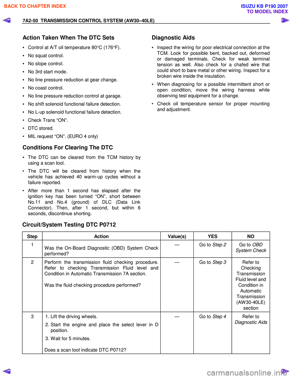
Circuit/System Testing DTC P0712
Step Action Value(s) YES NO
1
W as the On-Board Diagnostic (OBD) System Check
performed? — Go to
Step 2 Go to OBD
System Check
2 Perform the transmission fluid checking procedure. Refer to checking Transmission Fluid level and
Condition in Automatic Transmission 7A section.
W as the fluid checking procedure performed? — Go to
Step 3 Refer to
Checking
Transmission
Fluid level and Condition in Automatic
Transmission
(AW 30-40LE) section
3 1. Lift the driving wheels.
2. Start the engine and place the select lever in D
position.
3. W ait for 5 minutes.
Does a scan tool indicate DTC P0712? — Go to
Step 4 Refer to
Diagnostic Aids
BACK TO CHAPTER INDEX
TO MODEL INDEX
ISUZU KB P190 2007