2007 ISUZU KB P190 Wiring harness
[x] Cancel search: Wiring harnessPage 4935 of 6020
TRANSFER CONTROL SYSTEM 7D1-61
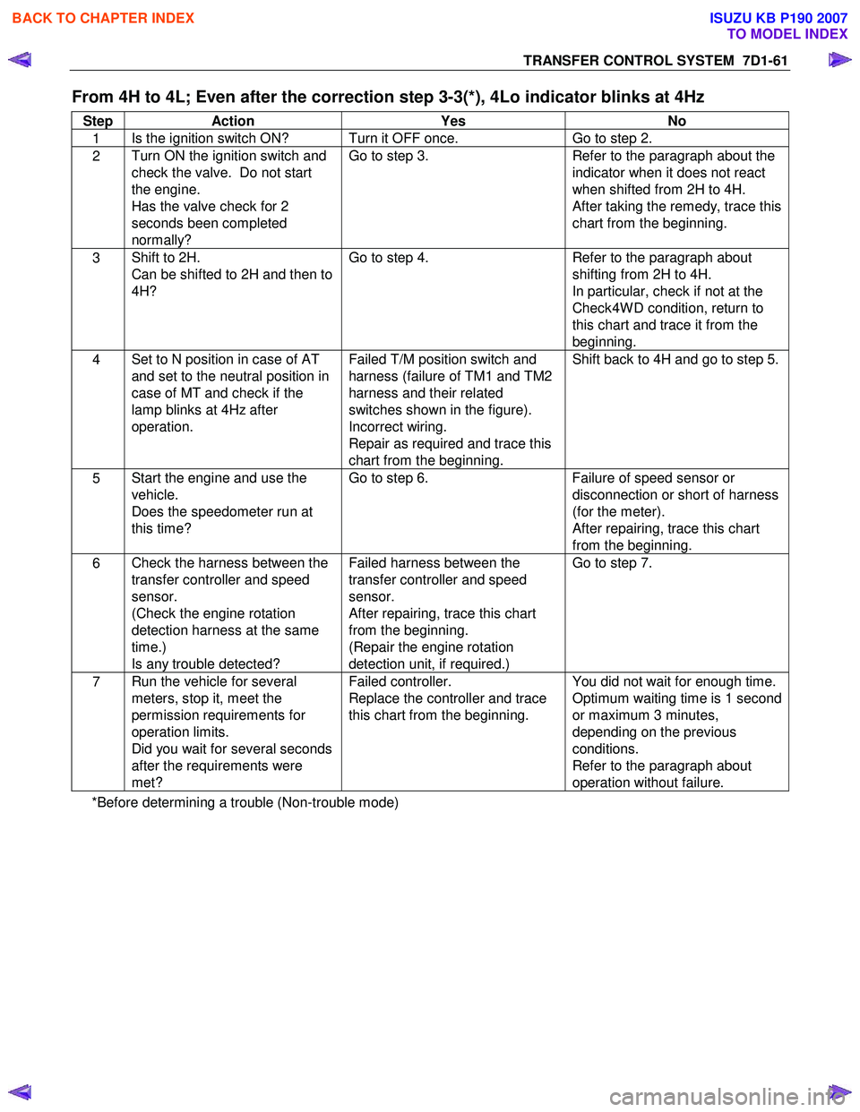
From 4H to 4L; Even after the correction step 3-3(*), 4Lo indicator blinks at 4Hz
Step Action Yes No
1 Is the ignition switch ON? Turn it OFF once.
Go to step 2.
2 Turn ON the ignition switch and
check the valve. Do not start
the engine.
Has the valve check for 2
seconds been completed
normally? Go to step 3.
Refer to the paragraph about the
indicator when it does not react
when shifted from 2H to 4H.
After taking the remedy, trace this
chart from the beginning.
3 Shift to 2H.
Can be shifted to 2H and then to
4H? Go to step 4.
Refer to the paragraph about
shifting from 2H to 4H.
In particular, check if not at the
Check4W D condition, return to
this chart and trace it from the
beginning.
4 Set to N position in case of AT
and set to the neutral position in
case of MT and check if the
lamp blinks at 4Hz after
operation.
Failed T/M position switch and
harness (failure of TM1 and TM2
harness and their related
switches shown in the figure).
Incorrect wiring.
Repair as required and trace this
chart from the beginning. Shift back to 4H and go to step 5.
5
Start the engine and use the
vehicle.
Does the speedometer run at
this time? Go to step 6.
Failure of speed sensor or
disconnection or short of harness
(for the meter).
After repairing, trace this chart
from the beginning.
6 Check the harness between the
transfer controller and speed
sensor.
(Check the engine rotation
detection harness at the same
time.)
Is any trouble detected? Failed harness between the
transfer controller and speed
sensor.
After repairing, trace this chart
from the beginning.
(Repair the engine rotation
detection unit, if required.) Go to step 7.
7
Run the vehicle for several
meters, stop it, meet the
permission requirements for
operation limits.
Did you wait for several seconds
after the requirements were
met? Failed controller.
Replace the controller and trace
this chart from the beginning. You did not wait for enough time.
Optimum waiting time is 1 second
or maximum 3 minutes,
depending on the previous
conditions.
Refer to the paragraph about
operation without failure.
*Before determining a trouble (Non-trouble mode)
BACK TO CHAPTER INDEX
TO MODEL INDEX
ISUZU KB P190 2007
Page 4936 of 6020
7D1-62 TRANSFER CONTROL SYSTEM
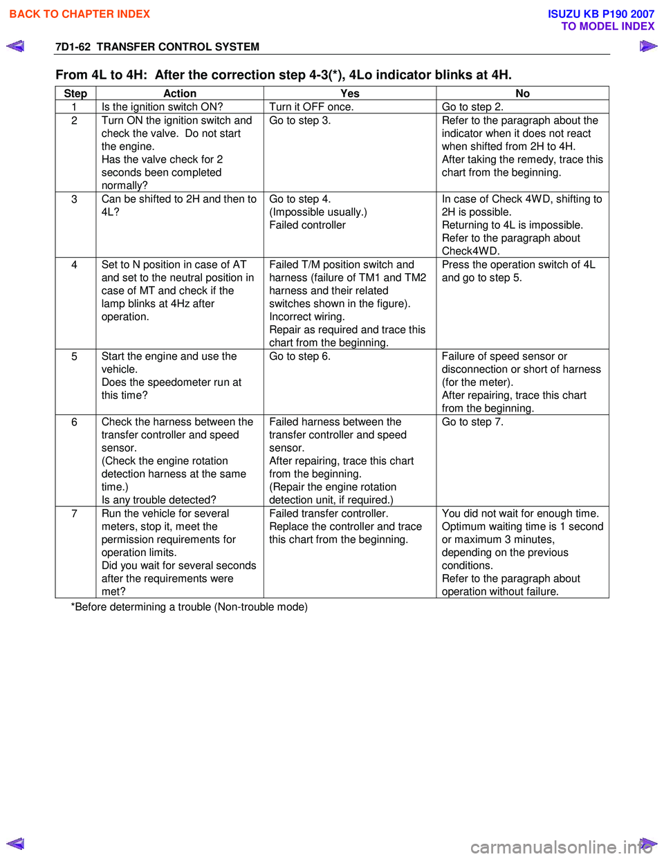
From 4L to 4H: After the correction step 4-3(*), 4Lo indicator blinks at 4H.
Step Action Yes No
1 Is the ignition switch ON? Turn it OFF once.
Go to step 2.
2 Turn ON the ignition switch and
check the valve. Do not start
the engine.
Has the valve check for 2
seconds been completed
normally? Go to step 3.
Refer to the paragraph about the
indicator when it does not react
when shifted from 2H to 4H.
After taking the remedy, trace this
chart from the beginning.
3 Can be shifted to 2H and then to
4L? Go to step 4.
(Impossible usually.)
Failed controller In case of Check 4W D, shifting to
2H is possible.
Returning to 4L is impossible.
Refer to the paragraph about
Check4W D.
4 Set to N position in case of AT
and set to the neutral position in
case of MT and check if the
lamp blinks at 4Hz after
operation.
Failed T/M position switch and
harness (failure of TM1 and TM2
harness and their related
switches shown in the figure).
Incorrect wiring.
Repair as required and trace this
chart from the beginning. Press the operation switch of 4L
and go to step 5.
5 Start the engine and use the
vehicle.
Does the speedometer run at
this time? Go to step 6.
Failure of speed sensor or
disconnection or short of harness
(for the meter).
After repairing, trace this chart
from the beginning.
6 Check the harness between the
transfer controller and speed
sensor.
(Check the engine rotation
detection harness at the same
time.)
Is any trouble detected? Failed harness between the
transfer controller and speed
sensor.
After repairing, trace this chart
from the beginning.
(Repair the engine rotation
detection unit, if required.) Go to step 7.
7
Run the vehicle for several
meters, stop it, meet the
permission requirements for
operation limits.
Did you wait for several seconds
after the requirements were
met? Failed transfer controller.
Replace the controller and trace
this chart from the beginning. You did not wait for enough time.
Optimum waiting time is 1 second
or maximum 3 minutes,
depending on the previous
conditions.
Refer to the paragraph about
operation without failure.
*Before determining a trouble (Non-trouble mode)
BACK TO CHAPTER INDEX
TO MODEL INDEX
ISUZU KB P190 2007
Page 4937 of 6020
TRANSFER CONTROL SYSTEM 7D1-63
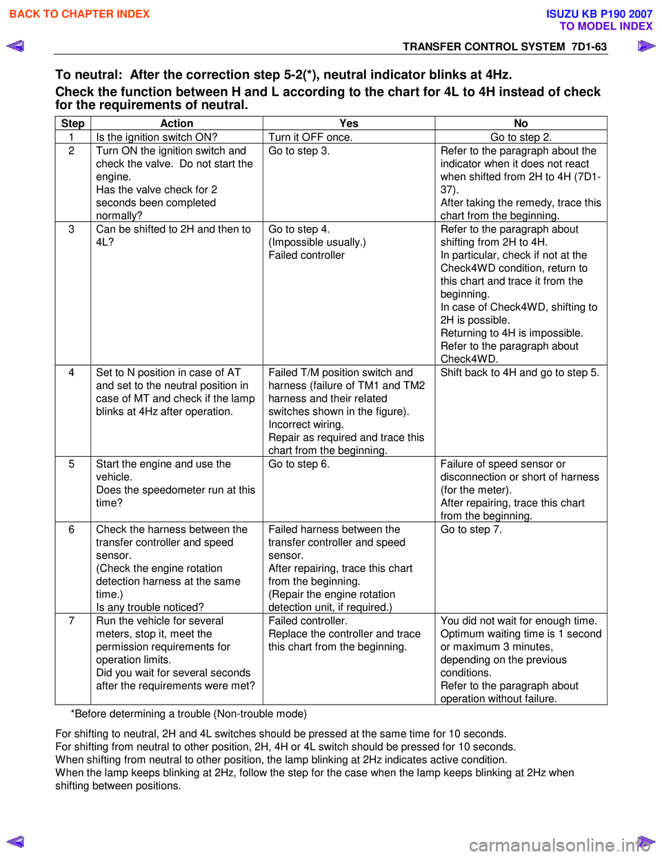
To neutral: After the correction step 5-2(*), neutral indicator blinks at 4Hz.
Check the function between H and L according to the chart for 4L to 4H instead of check
for the requirements of neutral.
Step Action Yes No
1 Is the ignition switch ON? Turn it OFF once. Go to step 2.
2 Turn ON the ignition switch and
check the valve. Do not start the
engine.
Has the valve check for 2
seconds been completed
normally? Go to step 3.
Refer to the paragraph about the
indicator when it does not react
when shifted from 2H to 4H (7D1-
37).
After taking the remedy, trace this
chart from the beginning.
3 Can be shifted to 2H and then to 4L? Go to step 4.
(Impossible usually.)
Failed controller Refer to the paragraph about
shifting from 2H to 4H.
In particular, check if not at the
Check4W D condition, return to
this chart and trace it from the
beginning.
In case of Check4W D, shifting to
2H is possible.
Returning to 4H is impossible.
Refer to the paragraph about
Check4W D.
4 Set to N position in case of AT and set to the neutral position in
case of MT and check if the lamp
blinks at 4Hz after operation. Failed T/M position switch and
harness (failure of TM1 and TM2
harness and their related
switches shown in the figure).
Incorrect wiring.
Repair as required and trace this
chart from the beginning. Shift back to 4H and go to step 5.
5 Start the engine and use the
vehicle.
Does the speedometer run at this
time? Go to step 6.
Failure of speed sensor or
disconnection or short of harness
(for the meter).
After repairing, trace this chart
from the beginning.
6 Check the harness between the transfer controller and speed
sensor.
(Check the engine rotation
detection harness at the same
time.)
Is any trouble noticed? Failed harness between the
transfer controller and speed
sensor.
After repairing, trace this chart
from the beginning.
(Repair the engine rotation
detection unit, if required.) Go to step 7.
7 Run the vehicle for several
meters, stop it, meet the
permission requirements for
operation limits.
Did you wait for several seconds
after the requirements were met? Failed controller.
Replace the controller and trace
this chart from the beginning. You did not wait for enough time.
Optimum waiting time is 1 second
or maximum 3 minutes,
depending on the previous
conditions.
Refer to the paragraph about
operation without failure.
*Before determining a trouble (Non-trouble mode)
For shifting to neutral, 2H and 4L switches should be pressed at the same time for 10 seconds.
For shifting from neutral to other position, 2H, 4H or 4L switch should be pressed for 10 seconds.
W hen shifting from neutral to other position, the lamp blinking at 2Hz indicates active condition.
W hen the lamp keeps blinking at 2Hz, follow the step for the case when the lamp keeps blinking at 2Hz when
shifting between positions.
BACK TO CHAPTER INDEX
TO MODEL INDEX
ISUZU KB P190 2007
Page 4945 of 6020
ELECTRICAL-BODY AND CHASSIS 8A-7
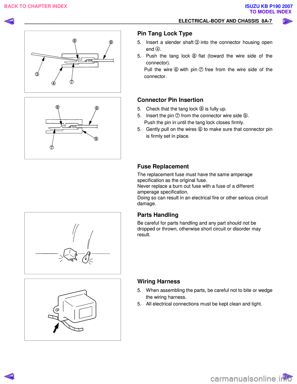
Pin Tang Lock Type
5. Insert a slender shaft 3into the connector housing open
end
4.
5. Push the tang lock
8flat (toward the wire side of the
connector).
Pull the wire
6 with pin 7free from the wire side of the
connector.
Connector Pin Insertion
5. Check that the tang lock 8 is fully up.
5. Insert the pin
7 from the connector wire side 9.
Push the pin in until the tang lock closes firmly.
5. Gently pull on the wires
6to make sure that connector pin
is firmly set in place.
Fuse Replacement
The replacement fuse must have the same amperage
specification as the original fuse.
Never replace a burn out fuse with a fuse of a different
amperage specification.
Doing so can result in an electrical fire or other serious circuit
damage.
Parts Handling
Be careful for parts handling and any part should not be
dropped or thrown, otherwise short circuit or disorder may
result.
Wiring Harness
5. W hen assembling the parts, be careful not to bite or wedge
the wiring harness.
5. All electrical connections must be kept clean and tight.
BACK TO CHAPTER INDEX TO MODEL INDEXISUZU KB P190 2007
Page 4946 of 6020
8A-8 ELECTRICAL-BODY AND CHASSIS
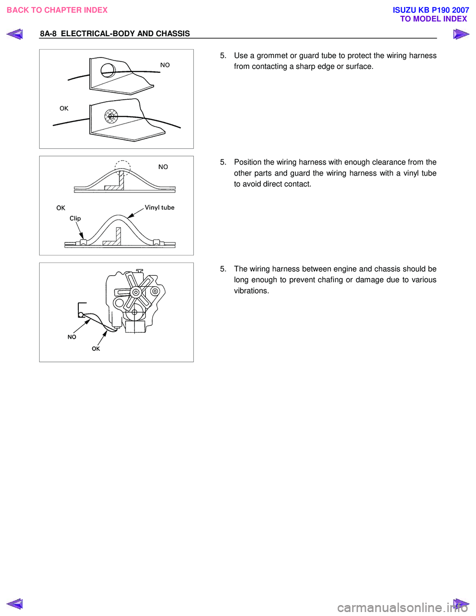
5. Use a grommet or guard tube to protect the wiring harness
from contacting a sharp edge or surface.
5. Position the wiring harness with enough clearance from the
other parts and guard the wiring harness with a vinyl tube
to avoid direct contact.
5. The wiring harness between engine and chassis should be
long enough to prevent chafing or damage due to various
vibrations.
BACK TO CHAPTER INDEX TO MODEL INDEXISUZU KB P190 2007
Page 4951 of 6020
ELECTRICAL-BODY AND CHASSIS 8A-13
PARTS FOR ELECTRICAL CIRCUIT
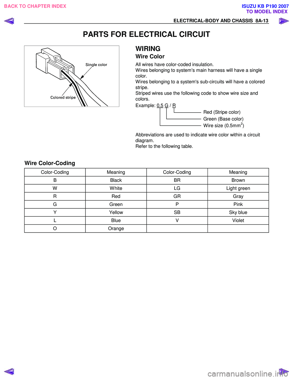
WIRING
Wire Color
All wires have color-coded insulation.
W ires belonging to system's main harness will have a single
color.
W ires belonging to a system's sub-circuits will have a colored
stripe.
Striped wires use the following code to show wire size and
colors.
Example: 0.5 G
/ R
Red (Stripe color)
Green (Base color)
W ire size (0.5mm
2)
Abbreviations are used to indicate wire color within a circuit
diagram.
Refer to the following table.
Wire Color-Coding
Color-Coding Meaning Color-Coding Meaning
B Black BR Brown
W W hite LG Light green
R Red GR Gray
G Green P Pink
Y Yellow SB Sky blue
L Blue V Violet
O Orange
BACK TO CHAPTER INDEX
TO MODEL INDEXISUZU KB P190 2007
Page 4953 of 6020
ELECTRICAL-BODY AND CHASSIS 8A-15
NormalBlown
FUSE
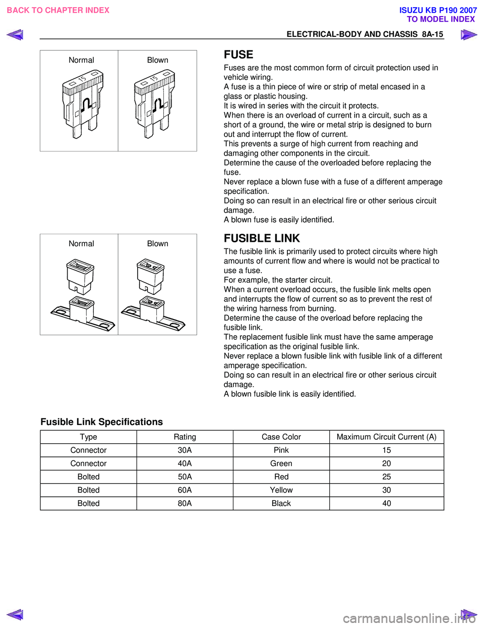
Fuses are the most common form of circuit protection used in
vehicle wiring.
A fuse is a thin piece of wire or strip of metal encased in a
glass or plastic housing.
It is wired in series with the circuit it protects.
W hen there is an overload of current in a circuit, such as a
short of a ground, the wire or metal strip is designed to burn
out and interrupt the flow of current.
This prevents a surge of high current from reaching and
damaging other components in the circuit.
Determine the cause of the overloaded before replacing the
fuse.
Never replace a blown fuse with a fuse of a different amperage
specification.
Doing so can result in an electrical fire or other serious circuit
damage.
A blown fuse is easily identified.
Normal Blown
FUSIBLE LINK
The fusible link is primarily used to protect circuits where high
amounts of current flow and where is would not be practical to
use a fuse.
For example, the starter circuit.
W hen a current overload occurs, the fusible link melts open
and interrupts the flow of current so as to prevent the rest of
the wiring harness from burning.
Determine the cause of the overload before replacing the
fusible link.
The replacement fusible link must have the same amperage
specification as the original fusible link.
Never replace a blown fusible link with fusible link of a different
amperage specification.
Doing so can result in an electrical fire or other serious circuit
damage.
A blown fusible link is easily identified.
Fusible Link Specifications
Type Rating Case Color Maximum Circuit Current (A)
Connector 30A Pink 15
Connector 40A Green 20
Bolted 50A Red 25
Bolted 60A Yellow 30
Bolted 80A Black 40
BACK TO CHAPTER INDEX
TO MODEL INDEXISUZU KB P190 2007
Page 5111 of 6020
ELECTRICAL-BODY AND CHASSIS 8A-173
RTW 780SH000901
RTW 780SH001001
HEADLIGHT BEAM SWITCH
(COMBINATION SWITCH)
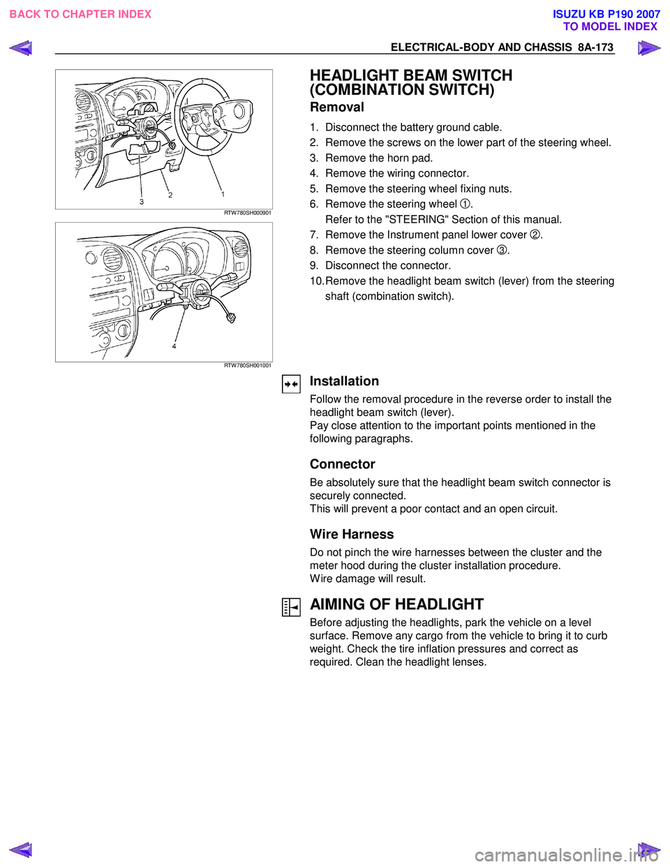
Removal
1. Disconnect the battery ground cable.
2. Remove the screws on the lower part of the steering wheel.
3. Remove the horn pad.
4. Remove the wiring connector.
5. Remove the steering wheel fixing nuts.
6. Remove the steering wheel
1.
Refer to the "STEERING" Section of this manual.
7. Remove the Instrument panel lower cover
2.
8. Remove the steering column cover
3.
9. Disconnect the connector.
10. Remove the headlight beam switch (lever) from the steering shaft (combination switch).
Installation
Follow the removal procedure in the reverse order to install the
headlight beam switch (lever).
Pay close attention to the important points mentioned in the
following paragraphs.
Connector
Be absolutely sure that the headlight beam switch connector is
securely connected.
This will prevent a poor contact and an open circuit.
Wire Harness
Do not pinch the wire harnesses between the cluster and the
meter hood during the cluster installation procedure.
W ire damage will result.
AIMING OF HEADLIGHT
Before adjusting the headlights, park the vehicle on a level
surface. Remove any cargo from the vehicle to bring it to curb
weight. Check the tire inflation pressures and correct as
required. Clean the headlight lenses.
BACK TO CHAPTER INDEX TO MODEL INDEXISUZU KB P190 2007