2007 ISUZU KB P190 Wiring harness
[x] Cancel search: Wiring harnessPage 3785 of 6020
Automatic Transmission – 4L60E – General Information Page 7C1–25
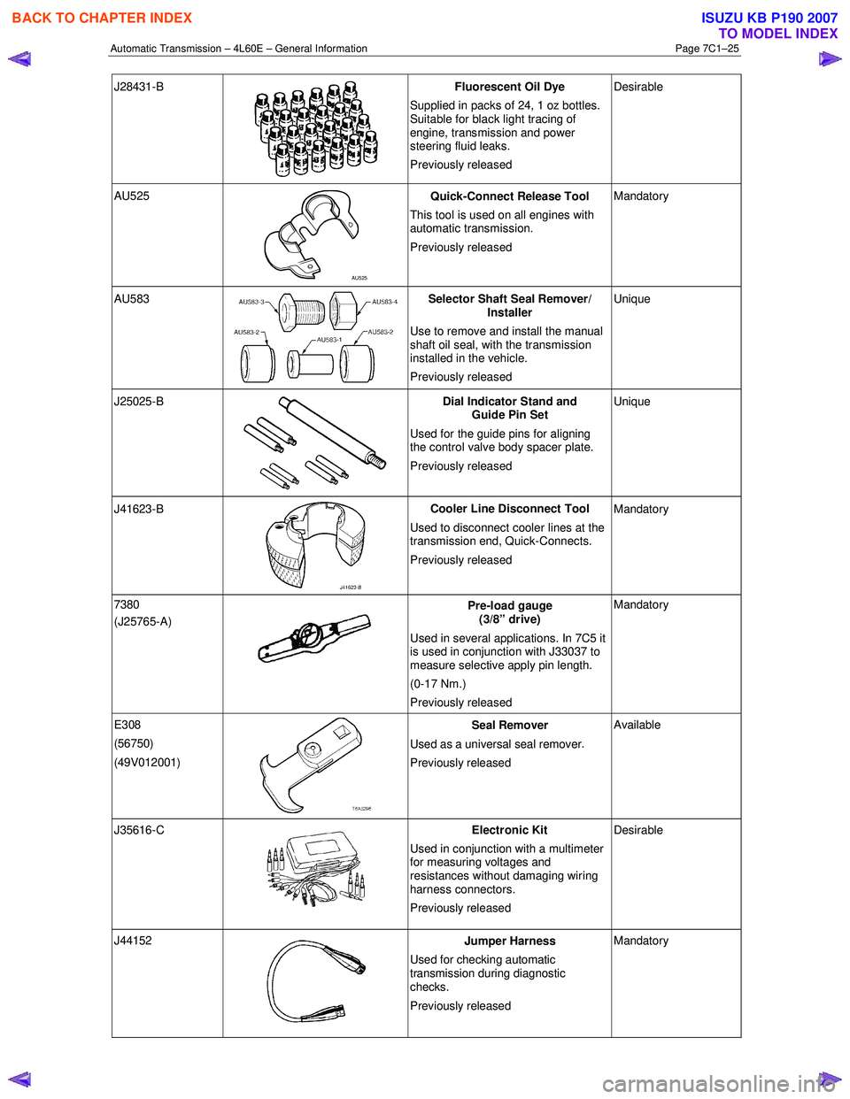
J28431-B
Fluorescent Oil Dye
Supplied in packs of 24, 1 oz bottles.
Suitable for black light tracing of
engine, transmission and power
steering fluid leaks.
Previously released Desirable
AU525
AU525 Quick-Connect Release Tool
This tool is used on all engines with
automatic transmission.
Previously released Mandatory
AU583 Selector Shaft Seal Remover/
Installer
Use to remove and install the manual
shaft oil seal, with the transmission
installed in the vehicle.
Previously released Unique
J25025-B
Dial Indicator Stand and
Guide Pin Set
Used for the guide pins for aligning
the control valve body spacer plate.
Previously released Unique
J41623-B
Cooler Line Disconnect Tool
Used to disconnect cooler lines at the
transmission end, Quick-Connects.
Previously released Mandatory
7380
(J25765-A)
Pre-load gauge
(3/8” drive)
Used in several applications. In 7C5 it
is used in conjunction with J33037 to
measure selective apply pin length.
(0-17 Nm.)
Previously released Mandatory
E308
(56750)
(49V012001)
Seal Remover
Used as a universal seal remover .
Previously released Available
J35616-C
Electronic Kit
Used in conjunction with a multimeter
for measuring voltages and
resistances without damaging wiring
harness connectors.
Previously released Desirable
J44152
Jumper Harness
Used for checking automatic
transmission during diagnostic
checks.
Previously released Mandatory
BACK TO CHAPTER INDEX
TO MODEL INDEX
ISUZU KB P190 2007
Page 3796 of 6020
Automatic Transmission – 4L60E – Electrical Diagnosis Page 7C2–10
Limp Home Mode Description
If a major electrical system failure occurs which could affect vehicle safety or damage the transmission during normal
operation, the TCM enters a limp home mode. In the limp home mode, the transmission operates in the following
manner:
• The pressure control solenoid is off and the line pressure is at maximum to minimise clutch slippage.
• The TCC solenoid is off, therefore the torque converter clutch is disabled.
• The two shift solenoids are turned off. The transmission will operate in fourth gear if the vehicle has successfully
completed a 1-2 upshift in the current ignition cycle. If the vehicle has not completed a 1-2 upshift in the current
ignition cycle, the transmission will operate in third gear. If the transmission is operating in fourth gear, third gear
may be obtained if the engine is stopped briefly and re-started.
In limp home mode, the gear selector lever is ineffective at selecting forward gear ranges. In third or fourth gear, heat
builds up in the transmission quickly, particularly in stop and go traffic. Excessive heat build-up may cause transmission
failure if the vehicle is driven for extended distances in limp home mode.
1.3 Transmission Indicators and Messages
For information pertaining to the instrument cluster and the transmission information it displays, refer to the RA Rodeo
Owner Handbook.
1.4 Electronic Component Description
For all other electrical components not covered in this section, refer to General Motors Powertrain Group Electronically
Controlled Automatic Transmission Technician's Guide.
Transmission Control Module (TCM)
The Transmission Control Module (TCM) is located under the instrument panel, next to the brake pedal assembly and
connects directly to the transmission wiring harness. A single 49-way connector is used to make the connection between
the vehicle wiring harness and the TCM.
To access the connector for diagnosis:
1 Ensure the ignition switch is in the OFF position.
2 Disconnect the connector (1) from the transmission control module (TCM) (2) as follows, refer to Figure 7C2 – 2: a remove the securing pin (3),
b press the locking tab and swing the lever (4) to free the connector,
c remove the connector.
BACK TO CHAPTER INDEX
TO MODEL INDEX
ISUZU KB P190 2007
Page 3813 of 6020
Automatic Transmission – 4L60E – Electrical Diagnosis Page 7C2–27
4 Diagnostics
4.1 Introduction
The transmission diagnostic procedure is organised in a logical structure that begins with the diagnostic system check
and as such must always be used as the starting point. The diagnostic system check directs the technician to the logical
steps necessary to diagnose a transmission driveability fault condition.
4.2 Basic Knowledge Required
A lack of basic understanding regarding
electronics, electrical wiring circuits and use
of electrical circuit testing tools when
performing any diagnostic procedure, could
result in incorrect diagnostic results or
damage to system components.
Understanding of the following is required to perform any of the diagnostic procedures detailed in this Service
Information:
• Basic electronics,
• Electrical wiring circuits,
• Electrical circuits testing, and
• Correct use of basic system diagnostic tools.
4.3 Diagnostic Precautions
When tests are required on connector
terminals, use the adapters in connector
adaptor kit J35616-C to prevent damage to
terminals.
The following precautions must be observed when performing all diagnostic procedures. Otherwise, incorrect diagnostic
results or damage to system components will occur:
1 Disconnection of the battery affects certain vehicle electronic systems.
2 Disconnect the battery negative lead when performing the following procedures:
• Disconnecting the electronic control module wiring harness connector/s or
• Charging the battery.
3 Disconnect the battery terminal ground lead and the electronic control module wiring harness connector before attempting any electric arc welding on the vehicle.
4 Do not start the engine if the battery terminal is not properly secured to the battery.
5 Do not disconnect or reconnect any of the following while the ignition is switched on or when the engine is running:
• Any electronic control module or system component electrical wiring connector, or
• Battery terminal leads.
6 Ensure that the correct procedure for disconnecting and connecting system electrical wiring harness connectors is always followed. For information on the correct procedure for disconnecting and connecting specific wiring
connectors, refer to 8A Electrical-Body and Chassis.
BACK TO CHAPTER INDEX
TO MODEL INDEX
ISUZU KB P190 2007
Page 3814 of 6020
Automatic Transmission – 4L60E – Electrical Diagnosis Page 7C2–28
7 Ensure that all wiring harness connectors are fitted correctly and secure.
8 W hen steam or pressure cleaning vehicle components, such as engines, transmissions, etc., do not direct the cleaning nozzle at any system electrical wiring harness connectors or components.
9 Do not clear any DTCs unless instructed.
10 The fault must be present when using the Diagnostic Trouble Code (DTC) Diagnostic Tables. Otherwise, misdiagnosis or replacement of good parts may occur.
11 Do not touch any electronic control module connector pins or soldered components on the circuit board. This is required to avoid the possibility of electrostatic discharge damage.
12 Use only the test equipment specified in the diagnostic tables, as other test equipment may give incorrect results or damage good components.
13 Electronic control modules are designed to withstand normal current draws associated with vehicle operation. However, the following fault conditions or incorrect test procedure may overload internal control module circuits and
irreparably damage the control module:
• A short to voltage fault condition in any of the control module low reference circuits may cause internal and/or
sensor damage. Therefore, any short to voltage fault condition in the control module low reference circuits
must be rectified before replacing a faulty component.
• A short to ground fault condition in any of the control module 5 volts reference circuits may cause internal
control module and/or sensor damage. Therefore, any short to ground fault condition in the control module 5
volt reference circuits must be rectified before replacing a faulty component.
• W hen using a test light to test an electrical circuit, do not use any of the control module low reference circuits
or 5 volts reference circuits as a reference point. Otherwise, excessive current draw from the test light may
damage the control module.
14 Disregard DTCs that set while performing the following diagnostic Steps:
• Using the Tech 2 output control function, or
• Disconnecting a control module system sensor connector then switching the ignition ON.
15 After completing the required diagnostics and service operations, road test the vehicle to ensure correct system operation.
4.4 Preliminary Checks
The Preliminary Checks is a set of visual and physical checks or inspections that may quickly identify a control module
system fault condition:
1 Refer to relevant Service Techlines for information regarding the fault condition.
2 Ensure that the battery is fully charged.
3 Inspect the battery connections for corrosion or a loose terminal.
4 Ensure that all relevant control module system related fuses are serviceable.
5 Inspect for incorrect aftermarket theft deterrent devices, lights or mobile phone installation.
6 Ensure that there is no speaker magnet positioned too close to any electronic module that contains relays.
7 Inspect the system wiring harness for proper connections, pinches or cuts.
8 Ensure that all control module related electrical wiring connectors are fitted correctly.
9 Inspect the control module ground connections for corrosion, loose terminal or incorrect position.
10 Ensure that the resistance between the control module housing and the battery ground cable is less than 0.5 ohms.
11 Check that the control module and its mounting bracket is secure.
12 Check all control module related components for correct installation.
13 Check the control module and related wiring harness routing to ensure that no rubbing or cutting of the wiring harness by sharp body components can occur.
BACK TO CHAPTER INDEX
TO MODEL INDEX
ISUZU KB P190 2007
Page 3832 of 6020
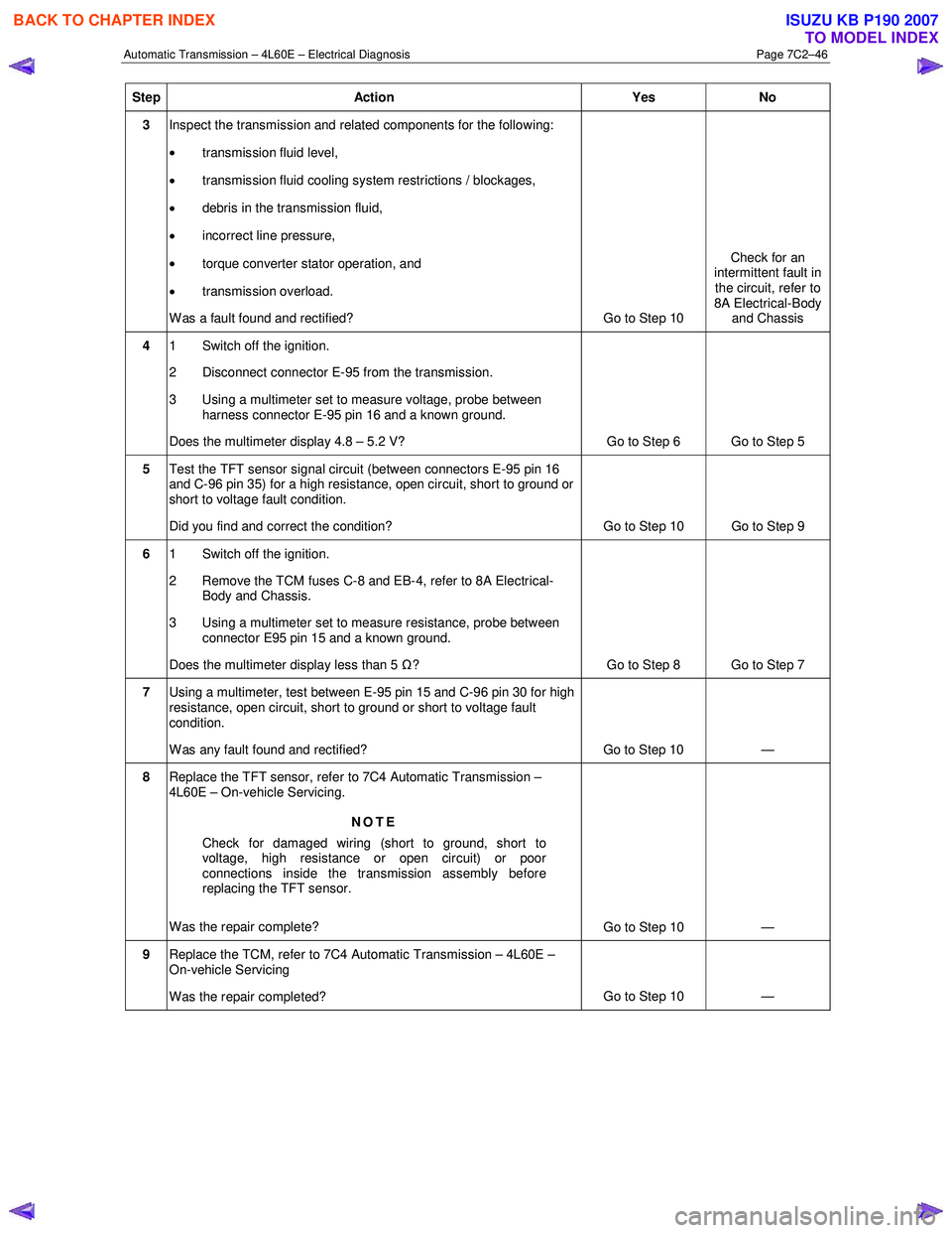
Automatic Transmission – 4L60E – Electrical Diagnosis Page 7C2–46
Step Action Yes No
3 Inspect the transmission and related components for the following:
• transmission fluid level,
• transmission fluid cooling system restrictions / blockages,
• debris in the transmission fluid,
• incorrect line pressure,
• torque converter stator operation, and
• transmission overload.
W as a fault found and rectified? Go to Step 10 Check for an
intermittent fault in
the circuit, refer to
8A Electrical-Body and Chassis
4 1 Switch off the ignition.
2 Disconnect connector E-95 from the transmission.
3 Using a multimeter set to measure voltage, probe between harness connector E-95 pin 16 and a known ground.
Does the multimeter display 4.8 – 5.2 V? Go to Step 6 Go to Step 5
5 Test the TFT sensor signal circuit (between connectors E-95 pin 16
and C-96 pin 35) for a high resistance, open circuit, short to ground or
short to voltage fault condition.
Did you find and correct the condition? Go to Step 10 Go to Step 9
6 1 Switch off the ignition.
2 Remove the TCM fuses C-8 and EB-4, refer to 8A Electrical- Body and Chassis.
3 Using a multimeter set to measure resistance, probe between connector E95 pin 15 and a known ground.
Does the multimeter display less than 5 Ω? Go to Step 8 Go to Step 7
7 Using a multimeter, test between E-95 pin 15 and C-96 pin 30 for high
resistance, open circuit, short to ground or short to voltage fault
condition.
W as any fault found and rectified? Go to Step 10 —
8 Replace the TFT sensor, refer to 7C4 Automatic Transmission –
4L60E – On-vehicle Servicing.
NOTE
Check for damaged wiring (short to ground, short to
voltage, high resistance or open circuit) or poor
connections inside the transmission assembly before
replacing the TFT sensor.
Was the repair complete? Go to Step 10 —
9 Replace the TCM, refer to 7C4 Automatic Transmission – 4L60E –
On-vehicle Servicing
Was the repair completed? Go to Step 10
—
BACK TO CHAPTER INDEX
TO MODEL INDEX
ISUZU KB P190 2007
Page 3860 of 6020
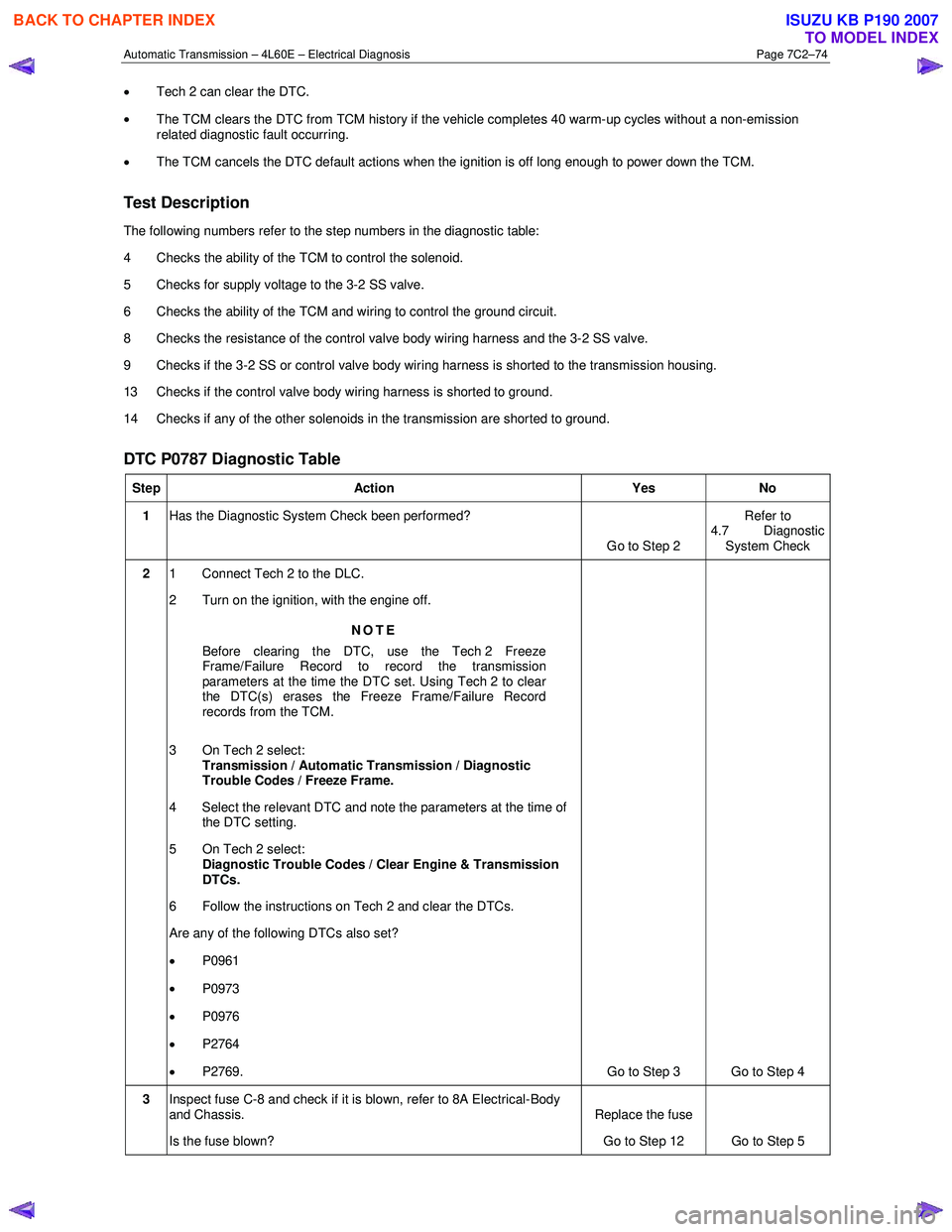
Automatic Transmission – 4L60E – Electrical Diagnosis Page 7C2–74
• Tech 2 can clear the DTC.
• The TCM clears the DTC from TCM history if the vehicle completes 40 warm-up cycles without a non-emission
related diagnostic fault occurring.
• The TCM cancels the DTC default actions when the ignition is off long enough to power down the TCM.
Test Description
The following numbers refer to the step numbers in the diagnostic table:
4 Checks the ability of the TCM to control the solenoid.
5 Checks for supply voltage to the 3-2 SS valve.
6 Checks the ability of the TCM and wiring to control the ground circuit.
8 Checks the resistance of the control valve body wiring harness and the 3-2 SS valve.
9 Checks if the 3-2 SS or control valve body wiring harness is shorted to the transmission housing.
13 Checks if the control valve body wiring harness is shorted to ground.
14 Checks if any of the other solenoids in the transmission are shorted to ground.
DTC P0787 Diagnostic Table
Step Action Yes No
1 Has the Diagnostic System Check been performed?
Go to Step 2 Refer to
4.7 Diagnostic System Check
2 1 Connect Tech 2 to the DLC.
2 Turn on the ignition, with the engine off.
NOTE
Before clearing the DTC, use the Tech 2 Freeze
Frame/Failure Record to record the transmission
parameters at the time the DTC set. Using Tech 2 to clear
the DTC(s) erases the Freeze Frame/Failure Record
records from the TCM.
3 On Tech 2 select: Transmission / Automatic Transmission / Diagnostic
Trouble Codes / Freeze Frame.
4 Select the relevant DTC and note the parameters at the time of the DTC setting.
5 On Tech 2 select:
Diagnostic Trouble Codes / Clear Engine & Transmission
DTCs.
6 Follow the instructions on Tech 2 and clear the DTCs.
Are any of the following DTCs also set?
• P0961
• P0973
• P0976
• P2764
• P2769. Go to Step 3 Go to Step 4
3 Inspect fuse C-8 and check if it is blown, refer to 8A Electrical-Body
and Chassis.
Is the fuse blown? Replace the fuse
Go to Step 12 Go to Step 5
BACK TO CHAPTER INDEX
TO MODEL INDEX
ISUZU KB P190 2007
Page 3861 of 6020
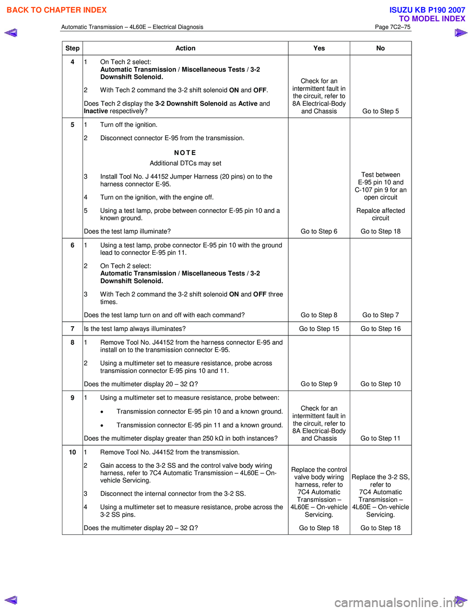
Automatic Transmission – 4L60E – Electrical Diagnosis Page 7C2–75
Step Action Yes No
4 1 On Tech 2 select:
Automatic Transmission / Miscellaneous Tests / 3-2
Downshift Solenoid.
2 With Tech 2 command the 3-2 shift solenoid ON and
OFF .
Does Tech 2 display the 3-2 Downshift Solenoid as Active and
Inactive respectively? Check for an
intermittent fault in the circuit, refer to
8A Electrical-Body and Chassis Go to Step 5
5 1 Turn off the ignition.
2 Disconnect connector E-95 from the transmission.
NOTE
Additional DTCs may set
3 Install Tool No. J 44152 Jumper Harness (20 pins) on to the harness connector E-95.
4 Turn on the ignition, with the engine off.
5 Using a test lamp, probe between connector E-95 pin 10 and a known ground.
Does the test lamp illuminate? Go to Step 6 Test between
E-95 pin 10 and
C-107 pin 9 for an open circuit
Repalce affected circuit
Go to Step 18
6 1 Using a test lamp, probe connector E-95 pin 10 with the ground
lead to connector E-95 pin 11.
2 On Tech 2 select: Automatic Transmission / Miscellaneous Tests / 3-2
Downshift Solenoid.
3 With Tech 2 command the 3-2 shift solenoid ON and OFF three
times.
Does the test lamp turn on and off with each command? Go to Step 8 Go to Step 7
7 Is the test lamp always illuminates? Go to Step 15 Go to Step 16
8 1 Remove Tool No. J44152 from the harness connector E-95 and
install on to the transmission connector E-95.
2 Using a multimeter set to measure resistance, probe across transmission connector E-95 pins 10 and 11.
Does the multimeter display 20 – 32 Ω? Go to Step 9 Go to Step 10
9 1 Using a multimeter set to measure resistance, probe between:
• Transmission connector E-95 pin 10 and a known ground.
• Transmission connector E-95 pin 11 and a known ground.
Does the multimeter display greater than 250 k Ω in both instances? Check for an
intermittent fault in
the circuit, refer to
8A Electrical-Body
and Chassis Go to Step 11
10 1 Remove Tool No. J44152 from the transmission.
2 Gain access to the 3-2 SS and the control valve body wiring harness, refer to 7C4 Automatic Transmission – 4L60E – On-
vehicle Servicing.
3 Disconnect the internal connector from the 3-2 SS.
4 Using a multimeter set to measure resistance, probe across the 3-2 SS pins.
Does the multimeter display 20 – 32 Ω? Replace the control
valve body wiring
harness, refer to 7C4 Automatic
Transmission –
4L60E – On-vehicle
Servicing.
Go to Step 18 Replace the 3-2 SS,
refer to
7C4 Automatic
Transmission –
4L60E – On-vehicle Servicing.
Go to Step 18
BACK TO CHAPTER INDEX
TO MODEL INDEX
ISUZU KB P190 2007
Page 3862 of 6020
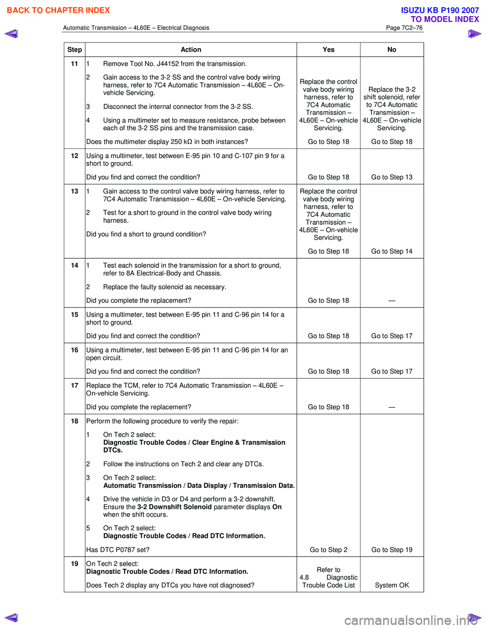
Automatic Transmission – 4L60E – Electrical Diagnosis Page 7C2–76
Step Action Yes No
11 1 Remove Tool No. J44152 from the transmission.
2 Gain access to the 3-2 SS and the control valve body wiring harness, refer to 7C4 Automatic Transmission – 4L60E – On-
vehicle Servicing.
3 Disconnect the internal connector from the 3-2 SS.
4 Using a multimeter set to measure resistance, probe between each of the 3-2 SS pins and the transmission case.
Does the multimeter display 250 k Ω in both instances? Replace the control
valve body wiring harness, refer to 7C4 Automatic
Transmission –
4L60E – On-vehicle Servicing.
Go to Step 18 Replace the 3-2
shift solenoid, refer to 7C4 Automatic
Transmission –
4L60E – On-vehicle Servicing.
Go to Step 18
12 Using a multimeter, test between E-95 pin 10 and C-107 pin 9 for a
short to ground.
Did you find and correct the condition? Go to Step 18 Go to Step 13
13 1 Gain access to the control valve body wiring harness, refer to
7C4 Automatic Transmission – 4L60E – On-vehicle Servicing.
2 Test for a short to ground in the control valve body wiring harness.
Did you find a short to ground condition? Replace the control
valve body wiring harness, refer to 7C4 Automatic
Transmission –
4L60E – On-vehicle Servicing.
Go to Step 18 Go to Step 14
14 1 Test each solenoid in the transmission for a short to ground,
refer to 8A Electrical-Body and Chassis.
2 Replace the faulty solenoid as necessary.
Did you complete the replacement? Go to Step 18 —
15 Using a multimeter, test between E-95 pin 11 and C-96 pin 14 for a
short to ground.
Did you find and correct the condition? Go to Step 18 Go to Step 17
16 Using a multimeter, test between E-95 pin 11 and C-96 pin 14 for an
open circuit.
Did you find and correct the condition? Go to Step 18 Go to Step 17
17 Replace the TCM, refer to 7C4 Automatic Transmission – 4L60E –
On-vehicle Servicing.
Did you complete the replacement? Go to Step 18
—
18 Perform the following procedure to verify the repair:
1 On Tech 2 select: Diagnostic Trouble Codes / Clear Engine & Transmission
DTCs.
2 Follow the instructions on Tech 2 and clear any DTCs.
3 On Tech 2 select: Automatic Transmission / Data Display / Transmission Data.
4 Drive the vehicle in D3 or D4 and perform a 3-2 downshift. Ensure the 3-2 Downshift Solenoid parameter displays On
when the shift occurs.
5 On Tech 2 select:
Diagnostic Trouble Codes / Read DTC Information.
Has DTC P0787 set? Go to Step 2 Go to Step 19
19 On Tech 2 select:
Diagnostic Trouble Codes / Read DTC Information.
Does Tech 2 display any DTCs you have not diagnosed? Refer to
4.8 Diagnostic
Trouble Code List System OK
BACK TO CHAPTER INDEX
TO MODEL INDEX
ISUZU KB P190 2007