2007 ISUZU KB P190 relay
[x] Cancel search: relayPage 2822 of 6020
Engine Mechanical – V6 Page 6A1–45
Page 6A1–45
2.15 Engine Compression Test
A compression pressure test of the engine cylinders determines the condition of the rings, the valves and the head
gasket.
Preliminary Steps
1 Ensure the battery is fully charged.
2 Remove the spark plugs from all cylinders, refer to Section 6C1-3 Engine Management – V6 – Service Operations.
NOTE
DTCs will set when the fuel system or the ignition
system is disabled and the engine is cranked.
Disregard DTCs that set under this condition.
3 Disable the fuel system by removi ng the fuel pump relay, refer to Section 8A Electrical Body & Chassis .
4 Start the engine to use any resi dual fuel from the fuel lines.
4 Disable the ignition coils by removing fuses 34 and 35, refer to Section 8A Electrical Body & Chassis .
5 Using Tech 2, command the throttle plate to wide open throttle.
Engine Cylinder Compression Test
1 Install the compression tester to cylinder number 1.
2 While observing the compression tester reading, turn t he ignition to the START position for several seconds and
then allow the ignition to return to the ON position.
3 Record the highest compression reading obtained.
4 Repeat the engine compression test for each cylinder.
Test Result Evaluation
Normal engine compression pressure builds quickly and evenly to over 965 kPa. In addition, the lowest reading of an
engine cylinder should not be less than 70 per cent of the highest reading. If any cylinder fails the compression test,
adding 15 ml of engine oil to the suspected cylinder may help isolate the following fault condition.
1 A fault condition in the piston rings will produce the following result:
• A low compression on the first engine cycle
• The compression tends to build-up with the succeeding engine rotation.
• The compression improves with the addition of engine oil.
2 A fault condition in an intake or exhaus t valve will produce the following result:
• A low compression on the first engine cycle
• The compression does not build with the succeeding engine rotation.
• The compression does not improve with the addition of engine oil.
3 A fault condition in the cylinder head gasket will produce the following result:
• A low compression on the first engine cycle
• The compression does not build with the succeeding engine rotation.
• The compression does not improve with the addition of engine oil.
• The suspected cylinders are pos itioned adjacent to each other.
• The engine oil may be contaminated with engine coolant.
• The engine coolant may be cont aminated with engine oil.
Once the fault has been identified, refe r to the relevant service procedure and reinstall the removed components.
Using Tech 2, clear DTCs.
BACK TO CHAPTER INDEX
TO MODEL INDEX
ISUZU KB P190 2007
Page 3210 of 6020
Fuel System – V6 Page 6C – 8
3 System Checks
3.1 Fuel Pump Flow Test
If a reduction of the fuel supply is suspected, perform the following checks.
1 Ensure there is sufficient fuel in the tank.
2 W ith the engine running, check the fuel lines from the fuel tank to the injectors for evidence of leakage.
Retighten, if the lines or the connections are loose.
Also, check the fuel lines for restrictions such as
squashed or clogged fuel line.
3 Depressurize the fuel system, refer to 3.4 Fuel System Depressurisation.
4 Disconnect the fuel line at the fuel rail.
5 Connect a hose from the fuel line and place the open end into a clean container.
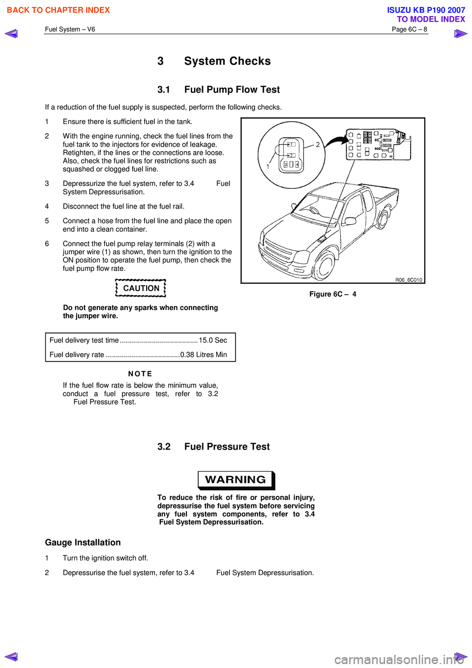
6 Connect the fuel pump relay terminals (2) with a jumper wire (1) as shown, then turn the ignition to the
ON position to operate the fuel pump, then check the
fuel pump flow rate.
Do not generate any sparks when connecting
the jumper wire.
Fuel delivery test time ....................................... 15.0 Sec
Fuel delivery rate .....................................0.38 Litres Min
NOTE
If the fuel flow rate is below the minimum value,
conduct a fuel pressure test, refer to 3.2
Fuel Pressure Test.
Figure 6C – 4
3.2 Fuel Pressure Test
To reduce the risk of fire or personal injury,
depressurise the fuel system before servicing
any fuel system components, refer to 3.4
Fuel System Depressurisation.
Gauge Installation
1 Turn the ignition switch off.
2 Depressurise the fuel system, refer to 3.4 Fuel System Depressurisation.
BACK TO CHAPTER INDEX
TO MODEL INDEX
ISUZU KB P190 2007
Page 3211 of 6020
Fuel System – V6 Page 6C – 9
A small amount of fuel may be released when
connecting the fuel pressure gauge to the fuel
pressure test point. Cover the fittings with a
shop towel to absorb any fuel spillage before
connecting the fuel pressure gauge. After the
fuel pressure test procedure, place the soiled
towel in an approved container for disposal.
3 At the fuel pressure test point, remove the Schrader valve sealing cap.
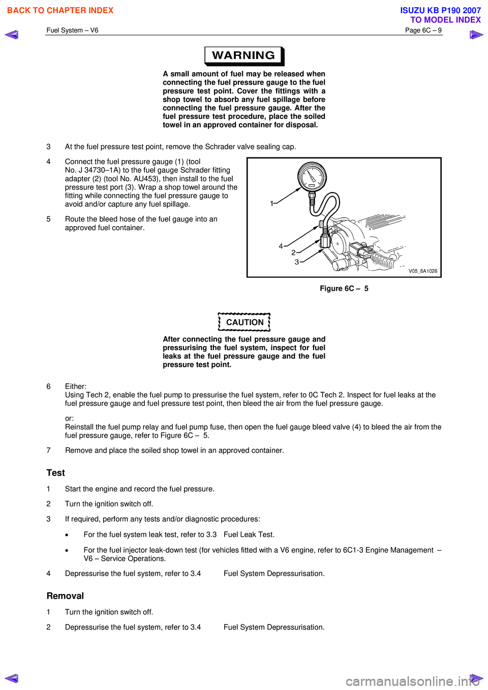
4 Connect the fuel pressure gauge (1) (tool No. J 34730–1A) to the fuel gauge Schrader fitting
adapter (2) (tool No. AU453), then install to the fuel
pressure test port (3). W rap a shop towel around the
fitting while connecting the fuel pressure gauge to
avoid and/or capture any fuel spillage.
5 Route the bleed hose of the fuel gauge into an approved fuel container.
Figure 6C – 5
After connecting the fuel pressure gauge and
pressurising the fuel system, inspect for fuel
leaks at the fuel pressure gauge and the fuel
pressure test point.
6 Either: Using Tech 2, enable the fuel pump to pressurise the fuel system, refer to 0C Tech 2. Inspect for fuel leaks at the
fuel pressure gauge and fuel pressure test point, then bleed the air from the fuel pressure gauge.
or: Reinstall the fuel pump relay and fuel pump fuse, then open the fuel gauge bleed valve (4) to bleed the air from the
fuel pressure gauge, refer to Figure 6C – 5.
7 Remove and place the soiled shop towel in an approved container.
Test
1 Start the engine and record the fuel pressure.
2 Turn the ignition switch off.
3 If required, perform any tests and/or diagnostic procedures:
• For the fuel system leak test, refer to 3.3 Fuel Leak Test.
• For the fuel injector leak-down test (for vehicles fitted with a V6 engine, refer to 6C1-3 Engine Management –
V6 – Service Operations.
4 Depressurise the fuel system, refer to 3.4 Fuel System Depressurisation.
Removal
1 Turn the ignition switch off.
2 Depressurise the fuel system, refer to 3.4 Fuel System Depressurisation.
BACK TO CHAPTER INDEX
TO MODEL INDEX
ISUZU KB P190 2007
Page 3213 of 6020
Fuel System – V6 Page 6C – 11
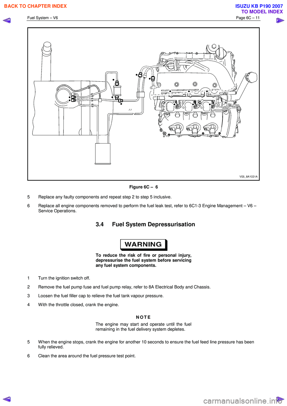
Figure 6C – 6
5 Replace any faulty components and repeat step 2 to step 5 inclusive.
6 Replace all engine components removed to perform the fuel leak test, refer to 6C1-3 Engine Management – V6 – Service Operations.
3.4 Fuel System Depressurisation
To reduce the risk of fire or personal injury,
depressurise the fuel system before servicing
any fuel system components.
1 Turn the ignition switch off.
2 Remove the fuel pump fuse and fuel pump relay, refer to 8A Electrical Body and Chassis.
3 Loosen the fuel filler cap to relieve the fuel tank vapour pressure.
4 W ith the throttle closed, crank the engine.
NOTE
The engine may start and operate until the fuel
remaining in the fuel delivery system depletes.
5 W hen the engine stops, crank the engine for another 10 seconds to ensure the fuel feed line pressure has been fully relieved.
6 Clean the area around the fuel pressure test point.
BACK TO CHAPTER INDEX
TO MODEL INDEX
ISUZU KB P190 2007
Page 3214 of 6020
Fuel System – V6 Page 6C – 12
A small amount of fuel may be released when
pressing on the Schrader valve. Cover the
fitting with a shop towel to absorb any fuel
spillage before removing the Schrader valve
sealing cap. Place the soiled towel in an
approved container for disposal.
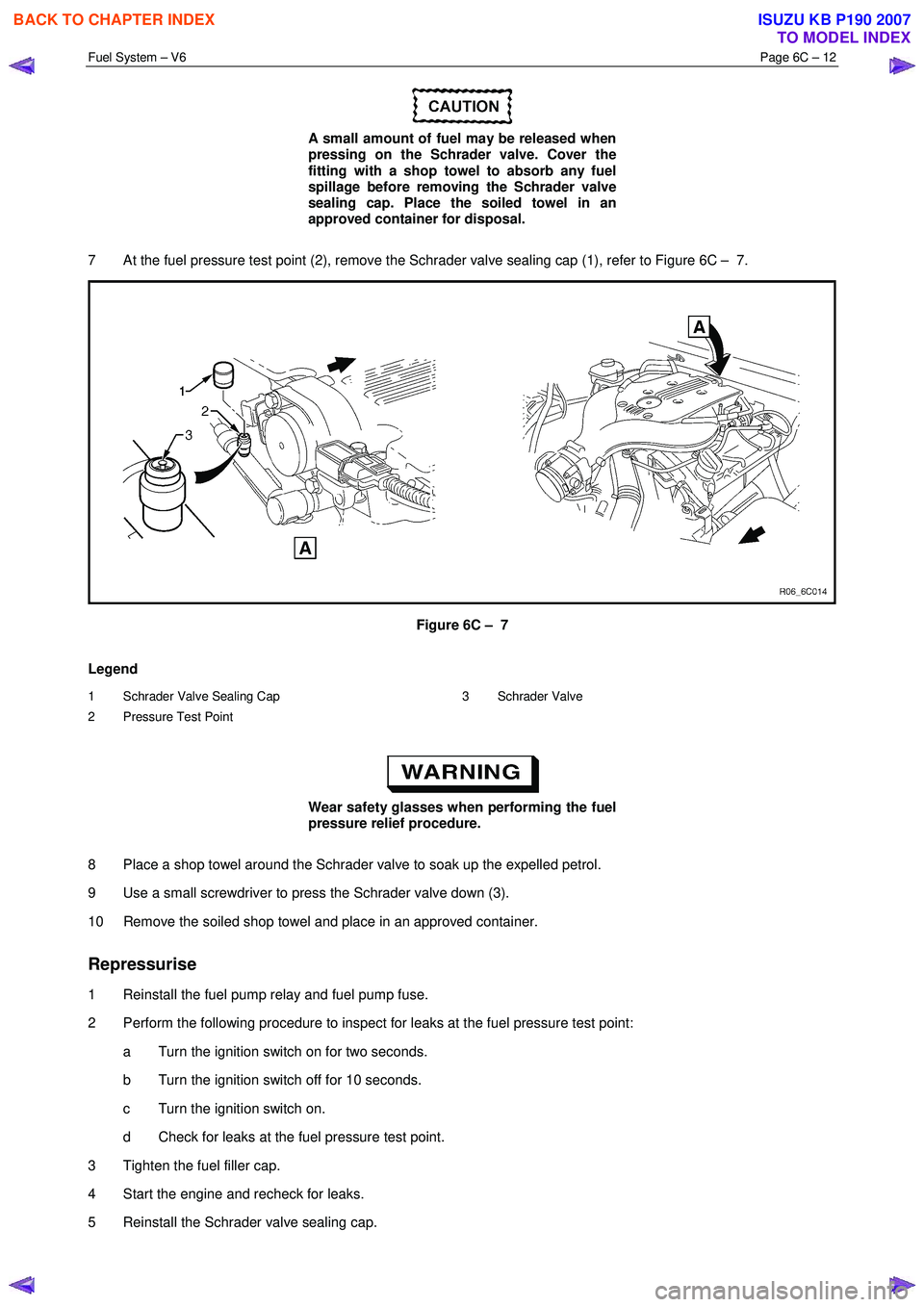
7 At the fuel pressure test point (2), remove the Schrader valve sealing cap (1), refer to Figure 6C – 7.
Figure 6C – 7
Legend
1 Schrader Valve Sealing Cap
2 Pressure Test Point 3 Schrader Valve
Wear safety glasses when performing the fuel
pressure relief procedure.
8 Place a shop towel around the Schrader valve to soak up the expelled petrol.
9 Use a small screwdriver to press the Schrader valve down (3).
10 Remove the soiled shop towel and place in an approved container.
Repressurise
1 Reinstall the fuel pump relay and fuel pump fuse.
2 Perform the following procedure to inspect for leaks at the fuel pressure test point: a Turn the ignition switch on for two seconds.
b Turn the ignition switch off for 10 seconds.
c Turn the ignition switch on.
d Check for leaks at the fuel pressure test point.
3 Tighten the fuel filler cap.
4 Start the engine and recheck for leaks.
5 Reinstall the Schrader valve sealing cap.
BACK TO CHAPTER INDEX
TO MODEL INDEX
ISUZU KB P190 2007
Page 3221 of 6020
Fuel System – V6 Page 6C – 19
Remove
• A depressurised fuel system contains fuel
in the fuel filter and fuel lines that can be
spilled during service operations.
• Fuel vapour remains in the fuel tank even
when completely empty. Seal all openings
in the fuel tank using suitable material or a
plastic plug. Ensure no naked flames or
other ignition sources are nearby. Ensure
all cellular phones (and transmission
devices that may cause any metal objects
to become unintentional receiving
antennas) are switched off.
• Place a dry chemical (Class B) fire
extinguisher nearby before performing any
on-vehicle service procedures. Failure to
follow these precautions may result in
personal injury.
1 Remove the fuel pump relay, refer to 8A Electrical Body and Chassis.
2 Depressurise the fuel system, refer to 3.4 Fuel System Depressurisation.
Never drain or store fuel into an open
container, due to the possibility of fire or
explosion.
3 Siphon the fuel tank, using commercially-available equipment.
Before proceeding, clean all traces of dirt and
other foreign material from the top of the fuel
tank, near the modular fuel pump and sender
assembly.
7 Place a drain tray under the fuel filter area.
Fuel can spill from the disconnected filter.
BACK TO CHAPTER INDEX
TO MODEL INDEX
ISUZU KB P190 2007
Page 3225 of 6020
Fuel System – V6 Page 6C – 23
4.5 Modular Fuel Pump and Sender
Assembly
NOTE
If the modular fuel pump and sender assembly
develops a fault it must be replaced as a
complete unit. The only serviced parts are the
retainer locking ring and the O-ring seal.
Remove
• A depressurised fuel system contains fuel
in the fuel filter and fuel lines that can be
spilled during service operations.
• Fuel vapour remains in the fuel tank even
when completely empty. Seal all openings
in the fuel tank using suitable material or a
plastic plug. Ensure no naked flames or
other ignition sources are nearby. Ensure
all cellular phones (and transmission
devices that may cause any metal objects
to become unintentional receiving
antennas) are switched off.
• Place a dry chemical (Class B) fire
extinguisher nearby before performing any
on-vehicle service procedures. Failure to
follow these precautions may result in
personal injury.
• Wear safety glasses when using
compressed air. Do not blow compressed
air directly onto any body part.
1 Remove the fuel pump relay, refer to 8A Engine Body and Chassis.
2 Remove the fuel tank assembly from the vehicle, refer to 4.4 Fuel Tank.
Before proceeding, clean all traces of dirt and
other foreign material from the top of the fuel
tank, near the modular fuel pump and sender
assembly.
3 Use compressed air to ensure all dirt and foreign materials are removed from all fuel connections before disconnecting the parts.
Fuel can spill from the disconnected modular
fuel pump and sender assembly.
BACK TO CHAPTER INDEX
TO MODEL INDEX
ISUZU KB P190 2007
Page 3232 of 6020
Fuel System – V6 Page 6C – 30
4.7 Fuel Tank Siphon Procedure
• Fuel vapour remains in the modular fuel
pump and sender assembly and fuel lines
that can be spilled during service
operations. Ensure no naked flames or
other ignition sources are nearby. Ensure
all cellular phones (and transmission
devices that may cause any metal objects
to become unintentional receiving
antennas) are switched off.
• Place a dry chemical (Class B) fire
extinguisher nearby before performing any
on-vehicle service procedures. Failure to
follow these precautions may result in
personal injury.
For an exploded view of fuel tank components, refer Figure 6C – 17.
1 Depressurise the fuel system, refer to 3.4 Fuel System Depressurisation.
2 Reinstall the fuel pump relay, refer to 8A Electrical Body and Chassis.
Disconnecting the battery affects certain
vehicle electronic systems. 1.1 WARNING,
CAUTION and NOTES.
3 Disconnect the negative battery terminal.
4 Remove the fuel filler cap.
NOTE
Lubricate the fuel siphon hose with J36850
TransJel Transmission Assembly Lubricant or
equivalent to aid hose insertion. Use only an
approved lubricant.
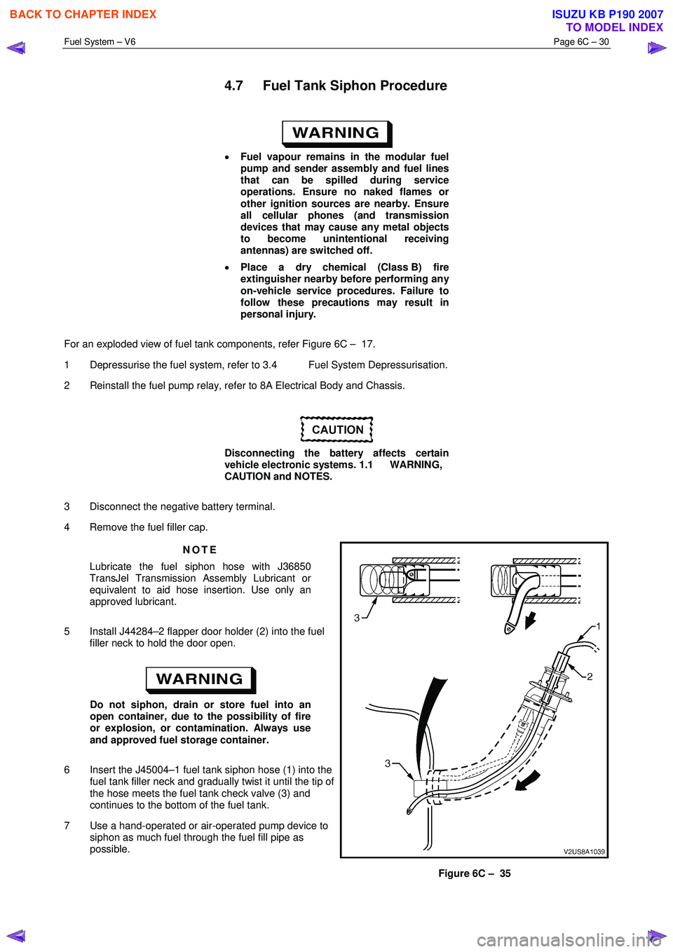
5 Install J44284–2 flapper door holder (2) into the fuel filler neck to hold the door open.
Do not siphon, drain or store fuel into an
open container, due to the possibility of fire
or explosion, or contamination. Always use
and approved fuel storage container.
6 Insert the J45004–1 fuel tank siphon hose (1) into the fuel tank filler neck and gradually twist it until the tip of
the hose meets the fuel tank check valve (3) and
continues to the bottom of the fuel tank.
7 Use a hand-operated or air-operated pump device to siphon as much fuel through the fuel fill pipe as
possible.
Figure 6C – 35
BACK TO CHAPTER INDEX
TO MODEL INDEX
ISUZU KB P190 2007