2007 ISUZU KB P190 relay
[x] Cancel search: relayPage 3338 of 6020
Engine Management – V6 – Diagnostics Page 6C1-2–60
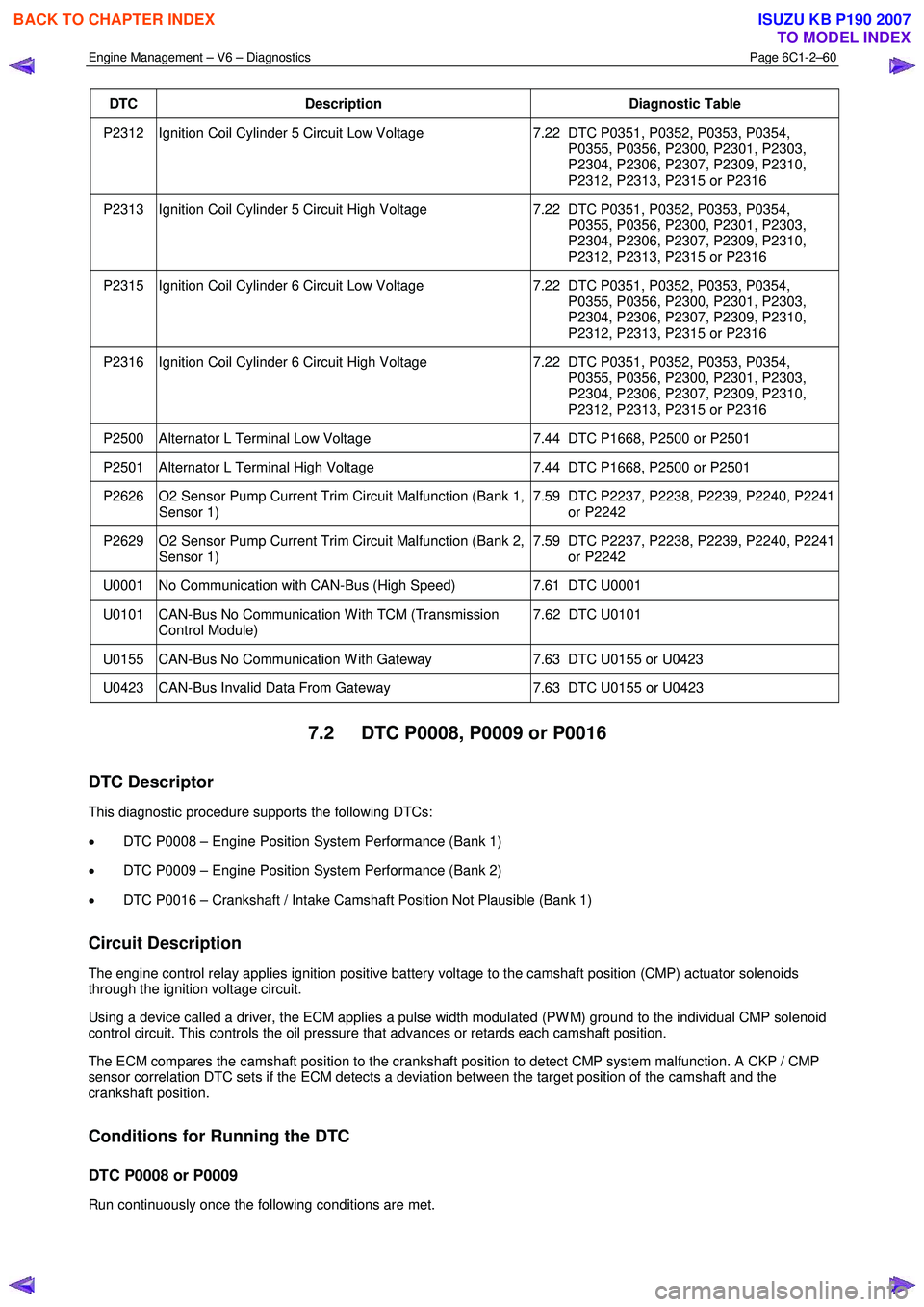
DTC Description Diagnostic Table
P2312 Ignition Coil Cylinder 5 Circuit Low Voltage 7.22 DTC P0351, P0352, P0353, P0354,
P0355, P0356, P2300, P2301, P2303,
P2304, P2306, P2307, P2309, P2310,
P2312, P2313, P2315 or P2316
P2313 Ignition Coil Cylinder 5 Circuit High Voltage 7.22 DTC P0351, P0352, P0353, P0354,
P0355, P0356, P2300, P2301, P2303,
P2304, P2306, P2307, P2309, P2310,
P2312, P2313, P2315 or P2316
P2315 Ignition Coil Cylinder 6 Circuit Low Voltage 7.22 DTC P0351, P0352, P0353, P0354,
P0355, P0356, P2300, P2301, P2303,
P2304, P2306, P2307, P2309, P2310,
P2312, P2313, P2315 or P2316
P2316 Ignition Coil Cylinder 6 Circuit High Voltage 7.22 DTC P0351, P0352, P0353, P0354,
P0355, P0356, P2300, P2301, P2303,
P2304, P2306, P2307, P2309, P2310,
P2312, P2313, P2315 or P2316
P2500 Alternator L Terminal Low Voltage 7.44 DTC P1668, P2500 or P2501
P2501 Alternator L Terminal High Voltage 7.44 DTC P1668, P2500 or P2501
P2626 O2 Sensor Pump Current Trim Circuit Malfunction (Bank 1,
Sensor 1) 7.59 DTC P2237, P2238, P2239, P2240, P2241
or P2242
P2629 O2 Sensor Pump Current Trim Circuit Malfunction (Bank 2, Sensor 1) 7.59 DTC P2237, P2238, P2239, P2240, P2241
or P2242
U0001 No Communication with CAN-Bus (High Speed) 7.61 DTC U0001
U0101 CAN-Bus No Communication W ith TCM (Transmission
Control Module) 7.62 DTC U0101
U0155 CAN-Bus No Communication W ith Gateway
7.63 DTC U0155 or U0423
U0423 CAN-Bus Invalid Data From Gateway 7.63 DTC U0155 or U0423
7.2 DTC P0008, P0009 or P0016
DTC Descriptor
This diagnostic procedure supports the following DTCs:
• DTC P0008 – Engine Position System Performance (Bank 1)
• DTC P0009 – Engine Position System Performance (Bank 2)
• DTC P0016 – Crankshaft / Intake Camshaft Position Not Plausible (Bank 1)
Circuit Description
The engine control relay applies ignition positive battery voltage to the camshaft position (CMP) actuator solenoids
through the ignition voltage circuit.
Using a device called a driver, the ECM applies a pulse width modulated (PW M) ground to the individual CMP solenoid
control circuit. This controls the oil pressure that advances or retards each camshaft position.
The ECM compares the camshaft position to the crankshaft position to detect CMP system malfunction. A CKP / CMP
sensor correlation DTC sets if the ECM detects a deviation between the target position of the camshaft and the
crankshaft position.
Conditions for Running the DTC
DTC P0008 or P0009
Run continuously once the following conditions are met.
BACK TO CHAPTER INDEX
TO MODEL INDEX
ISUZU KB P190 2007
Page 3341 of 6020
Engine Management – V6 – Diagnostics Page 6C1-2–63
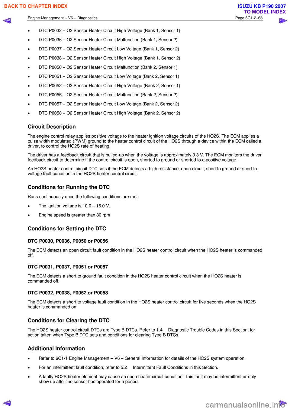
• DTC P0032 – O2 Sensor Heater Circuit High Voltage (Bank 1, Sensor 1)
• DTC P0036 – O2 Sensor Heater Circuit Malfunction (Bank 1, Sensor 2)
• DTC P0037 – O2 Sensor Heater Circuit Low Voltage (Bank 1, Sensor 2)
• DTC P0038 – O2 Sensor Heater Circuit High Voltage (Bank 1, Sensor 2)
• DTC P0050 – O2 Sensor Heater Circuit Malfunction (Bank 2, Sensor 1)
• DTC P0051 – O2 Sensor Heater Circuit Low Voltage (Bank 2, Sensor 1)
• DTC P0052 – O2 Sensor Heater Circuit High Voltage (Bank 2, Sensor 1)
• DTC P0056 – O2 Sensor Heater Circuit Malfunction (Bank 2, Sensor 2)
• DTC P0057 – O2 Sensor Heater Circuit Low Voltage (Bank 2, Sensor 2)
• DTC P0058 – O2 Sensor Heater Circuit High Voltage (Bank 2, Sensor 2)
Circuit Description
The engine control relay applies positive voltage to the heater ignition voltage circuits of the HO2S. The ECM applies a
pulse width modulated (PW M) ground to the heater control circuit of the HO2S through a device within the ECM called a
driver, to control the HO2S rate of heating.
The driver has a feedback circuit that is pulled-up when the voltage is approximately 3.3 V. The ECM monitors the driver
feedback circuit to determine if the control circuit is open, shorted to ground or shorted to a positive voltage.
An HO2S heater control circuit DTC sets if the ECM detects a high resistance, open circuit, short to ground or short to
voltage fault condition in the HO2S heater control circuit.
Conditions for Running the DTC
Runs continuously once the following conditions are met:
• The ignition voltage is 10.0 – 16.0 V.
• Engine speed is greater than 80 rpm
Conditions for Setting the DTC
DTC P0030, P0036, P0050 or P0056
The ECM detects an open circuit fault condition in the HO2S heater control circuit when the HO2S heater is commanded
off.
DTC P0031, P0037, P0051 or P0057
The ECM detects a short to ground fault condition in the HO2S heater control circuit when the HO2S heater is
commanded off.
DTC P0032, P0038, P0052 or P0058
The ECM detects a short to voltage fault condition in the HO2S heater control circuit for five seconds when the HO2S
heater is commanded on.
Conditions for Clearing the DTC
The HO2S heater control circuit DTCs are Type B DTCs. Refer to 1.4 Diagnostic Trouble Codes in this Section, for
action taken when Type B DTC sets and conditions for clearing Type B DTCs.
Additional Information
• Refer to 6C1-1 Engine Management – V6 – General Information for details of the HO2S system operation.
• For an intermittent fault condition, refer to 5.2 Intermittent Fault Conditions in this Section.
• A faulty HO2S heater element may cause an open heater circuit condition. This fault may be intermittent or only
show up after the sensor has operated for a period.
BACK TO CHAPTER INDEX
TO MODEL INDEX
ISUZU KB P190 2007
Page 3343 of 6020
Engine Management – V6 – Diagnostics Page 6C1-2–65
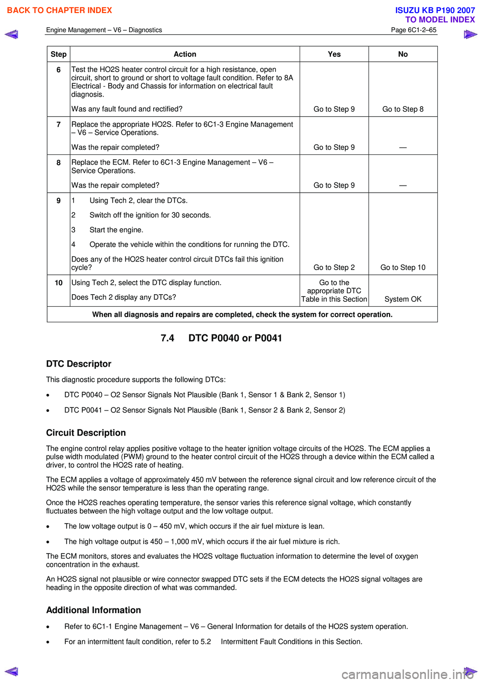
Step Action Yes No
6 Test the HO2S heater control circuit for a high resistance, open
circuit, short to ground or short to voltage fault condition. Refer to 8A
Electrical - Body and Chassis for information on electrical fault
diagnosis.
W as any fault found and rectified? Go to Step 9 Go to Step 8
7 Replace the appropriate HO2S. Refer to 6C1-3 Engine Management
– V6 – Service Operations.
W as the repair completed? Go to Step 9 —
8 Replace the ECM. Refer to 6C1-3 Engine Management – V6 –
Service Operations.
W as the repair completed? Go to Step 9 —
9 1 Using Tech 2, clear the DTCs.
2 Switch off the ignition for 30 seconds.
3 Start the engine.
4 Operate the vehicle within the conditions for running the DTC.
Does any of the HO2S heater control circuit DTCs fail this ignition
cycle? Go to Step 2 Go to Step 10
10 Using Tech 2, select the DTC display function.
Does Tech 2 display any DTCs? Go to the
appropriate DTC
Table in this Section System OK
When all diagnosis and repairs are completed, check the system for correct operation.
7.4 DTC P0040 or P0041
DTC Descriptor
This diagnostic procedure supports the following DTCs:
• DTC P0040 – O2 Sensor Signals Not Plausible (Bank 1, Sensor 1 & Bank 2, Sensor 1)
• DTC P0041 – O2 Sensor Signals Not Plausible (Bank 1, Sensor 2 & Bank 2, Sensor 2)
Circuit Description
The engine control relay applies positive voltage to the heater ignition voltage circuits of the HO2S. The ECM applies a
pulse width modulated (PW M) ground to the heater control circuit of the HO2S through a device within the ECM called a
driver, to control the HO2S rate of heating.
The ECM applies a voltage of approximately 450 mV between the reference signal circuit and low reference circuit of the
HO2S while the sensor temperature is less than the operating range.
Once the HO2S reaches operating temperature, the sensor varies this reference signal voltage, which constantly
fluctuates between the high voltage output and the low voltage output.
• The low voltage output is 0 – 450 mV, which occurs if the air fuel mixture is lean.
• The high voltage output is 450 – 1,000 mV, which occurs if the air fuel mixture is rich.
The ECM monitors, stores and evaluates the HO2S voltage fluctuation information to determine the level of oxygen
concentration in the exhaust.
An HO2S signal not plausible or wire connector swapped DTC sets if the ECM detects the HO2S signal voltages are
heading in the opposite direction of what was commanded.
Additional Information
• Refer to 6C1-1 Engine Management – V6 – General Information for details of the HO2S system operation.
• For an intermittent fault condition, refer to 5.2 Intermittent Fault Conditions in this Section.
BACK TO CHAPTER INDEX
TO MODEL INDEX
ISUZU KB P190 2007
Page 3345 of 6020
Engine Management – V6 – Diagnostics Page 6C1-2–67
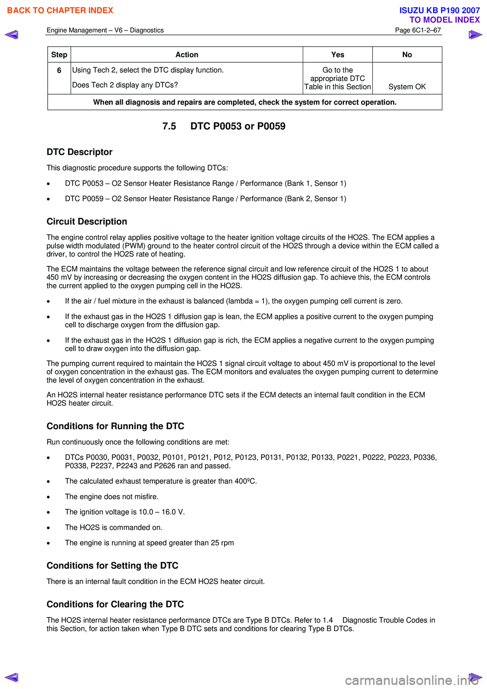
Step Action Yes No
6 Using Tech 2, select the DTC display function.
Does Tech 2 display any DTCs? Go to the
appropriate DTC
Table in this Section System OK
When all diagnosis and repairs are completed, check the system for correct operation.
7.5 DTC P0053 or P0059
DTC Descriptor
This diagnostic procedure supports the following DTCs:
• DTC P0053 – O2 Sensor Heater Resistance Range / Performance (Bank 1, Sensor 1)
• DTC P0059 – O2 Sensor Heater Resistance Range / Performance (Bank 2, Sensor 1)
Circuit Description
The engine control relay applies positive voltage to the heater ignition voltage circuits of the HO2S. The ECM applies a
pulse width modulated (PW M) ground to the heater control circuit of the HO2S through a device within the ECM called a
driver, to control the HO2S rate of heating.
The ECM maintains the voltage between the reference signal circuit and low reference circuit of the HO2S 1 to about
450 mV by increasing or decreasing the oxygen content in the HO2S diffusion gap. To achieve this, the ECM controls
the current applied to the oxygen pumping cell in the HO2S.
• If the air / fuel mixture in the exhaust is balanced (lambda = 1), the oxygen pumping cell current is zero.
• If the exhaust gas in the HO2S 1 diffusion gap is lean, the ECM applies a positive current to the oxygen pumping
cell to discharge oxygen from the diffusion gap.
• If the exhaust gas in the HO2S 1 diffusion gap is rich, the ECM applies a negative current to the oxygen pumping
cell to draw oxygen into the diffusion gap.
The pumping current required to maintain the HO2S 1 signal circuit voltage to about 450 mV is proportional to the level
of oxygen concentration in the exhaust gas. The ECM monitors and evaluates the oxygen pumping current to determine
the level of oxygen concentration in the exhaust.
An HO2S internal heater resistance performance DTC sets if the ECM detects an internal fault condition in the ECM
HO2S heater circuit.
Conditions for Running the DTC
Run continuously once the following conditions are met:
• DTCs P0030, P0031, P0032, P0101, P0121, P012, P0123, P0131, P0132, P0133, P0221, P0222, P0223, P0336,
P0338, P2237, P2243 and P2626 ran and passed.
• The calculated exhaust temperature is greater than 400ºC.
• The engine does not misfire.
• The ignition voltage is 10.0 – 16.0 V.
• The HO2S is commanded on.
• The engine is running at speed greater than 25 rpm
Conditions for Setting the DTC
There is an internal fault condition in the ECM HO2S heater circuit.
Conditions for Clearing the DTC
The HO2S internal heater resistance performance DTCs are Type B DTCs. Refer to 1.4 Diagnostic Trouble Codes in
this Section, for action taken when Type B DTC sets and conditions for clearing Type B DTCs.
BACK TO CHAPTER INDEX
TO MODEL INDEX
ISUZU KB P190 2007
Page 3347 of 6020
Engine Management – V6 – Diagnostics Page 6C1-2–69
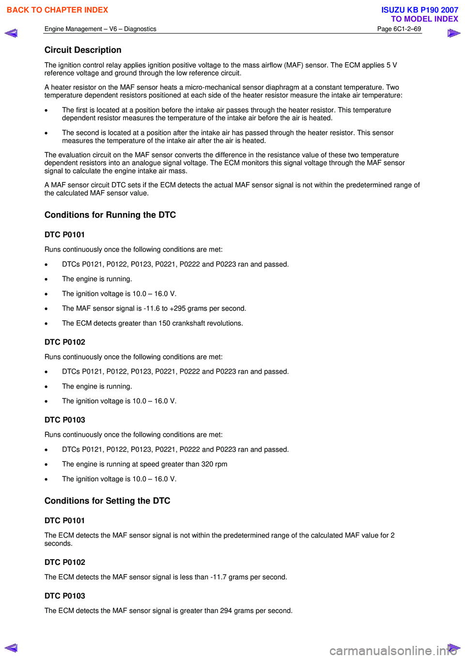
Circuit Description
The ignition control relay applies ignition positive voltage to the mass airflow (MAF) sensor. The ECM applies 5 V
reference voltage and ground through the low reference circuit.
A heater resistor on the MAF sensor heats a micro-mechanical sensor diaphragm at a constant temperature. Two
temperature dependent resistors positioned at each side of the heater resistor measure the intake air temperature:
• The first is located at a position before the intake air passes through the heater resistor. This temperature
dependent resistor measures the temperature of the intake air before the air is heated.
• The second is located at a position after the intake air has passed through the heater resistor. This sensor
measures the temperature of the intake air after the air is heated.
The evaluation circuit on the MAF sensor converts the difference in the resistance value of these two temperature
dependent resistors into an analogue signal voltage. The ECM monitors this signal voltage through the MAF sensor
signal to calculate the engine intake air mass.
A MAF sensor circuit DTC sets if the ECM detects the actual MAF sensor signal is not within the predetermined range of
the calculated MAF sensor value.
Conditions for Running the DTC
DTC P0101
Runs continuously once the following conditions are met:
• DTCs P0121, P0122, P0123, P0221, P0222 and P0223 ran and passed.
• The engine is running.
• The ignition voltage is 10.0 – 16.0 V.
• The MAF sensor signal is -11.6 to +295 grams per second.
• The ECM detects greater than 150 crankshaft revolutions.
DTC P0102
Runs continuously once the following conditions are met:
• DTCs P0121, P0122, P0123, P0221, P0222 and P0223 ran and passed.
• The engine is running.
• The ignition voltage is 10.0 – 16.0 V.
DTC P0103
Runs continuously once the following conditions are met:
• DTCs P0121, P0122, P0123, P0221, P0222 and P0223 ran and passed.
• The engine is running at speed greater than 320 rpm
• The ignition voltage is 10.0 – 16.0 V.
Conditions for Setting the DTC
DTC P0101
The ECM detects the MAF sensor signal is not within the predetermined range of the calculated MAF value for 2
seconds.
DTC P0102
The ECM detects the MAF sensor signal is less than -11.7 grams per second.
DTC P0103
The ECM detects the MAF sensor signal is greater than 294 grams per second.
BACK TO CHAPTER INDEX
TO MODEL INDEX
ISUZU KB P190 2007
Page 3348 of 6020
Engine Management – V6 – Diagnostics Page 6C1-2–70
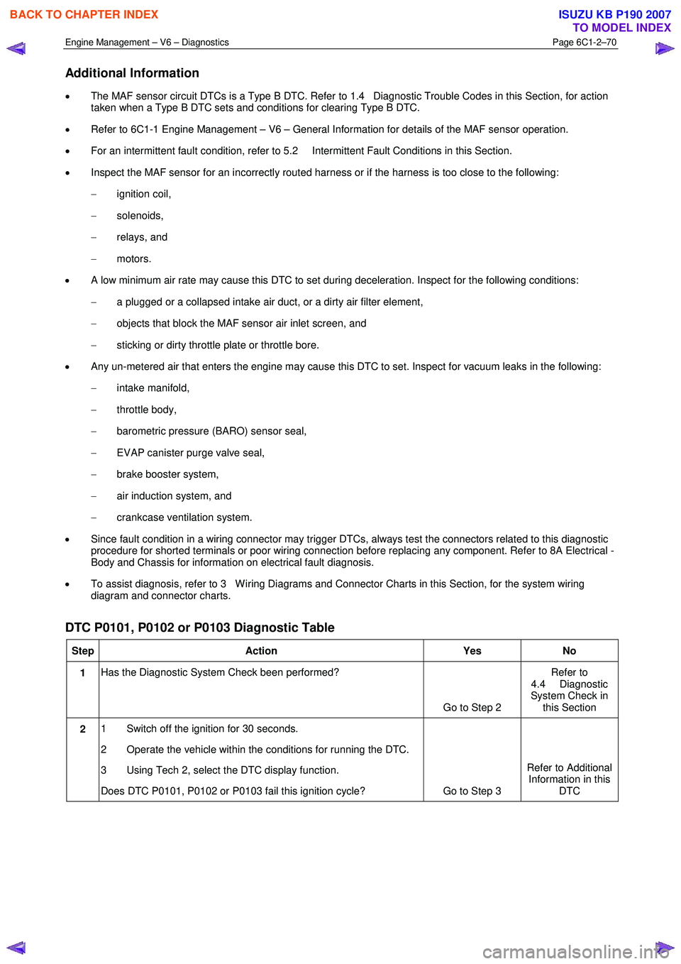
Additional Information
• The MAF sensor circuit DTCs is a Type B DTC. Refer to 1.4 Diagnostic Trouble Codes in this Section, for action
taken when a Type B DTC sets and conditions for clearing Type B DTC.
• Refer to 6C1-1 Engine Management – V6 – General Information for details of the MAF sensor operation.
• For an intermittent fault condition, refer to 5.2 Intermittent Fault Conditions in this Section.
• Inspect the MAF sensor for an incorrectly routed harness or if the harness is too close to the following:
− ignition coil,
− solenoids,
− relays, and
− motors.
• A low minimum air rate may cause this DTC to set during deceleration. Inspect for the following conditions:
− a plugged or a collapsed intake air duct, or a dirty air filter element,
− objects that block the MAF sensor air inlet screen, and
− sticking or dirty throttle plate or throttle bore.
• Any un-metered air that enters the engine may cause this DTC to set. Inspect for vacuum leaks in the following:
− intake manifold,
− throttle body,
− barometric pressure (BARO) sensor seal,
− EVAP canister purge valve seal,
− brake booster system,
− air induction system, and
− crankcase ventilation system.
• Since fault condition in a wiring connector may trigger DTCs, always test the connectors related to this diagnostic
procedure for shorted terminals or poor wiring connection before replacing any component. Refer to 8A Electrical -
Body and Chassis for information on electrical fault diagnosis.
• To assist diagnosis, refer to 3 W iring Diagrams and Connector Charts in this Section, for the system wiring
diagram and connector charts.
DTC P0101, P0102 or P0103 Diagnostic Table
Step Action Yes No
1 Has the Diagnostic System Check been performed?
Go to Step 2 Refer to
4.4 Diagnostic
System Check in this Section
2 1 Switch off the ignition for 30 seconds.
2 Operate the vehicle within the conditions for running the DTC.
3 Using Tech 2, select the DTC display function.
Does DTC P0101, P0102 or P0103 fail this ignition cycle? Go to Step 3 Refer to Additional
Information in this DTC
BACK TO CHAPTER INDEX
TO MODEL INDEX
ISUZU KB P190 2007
Page 3349 of 6020
Engine Management – V6 – Diagnostics Page 6C1-2–71
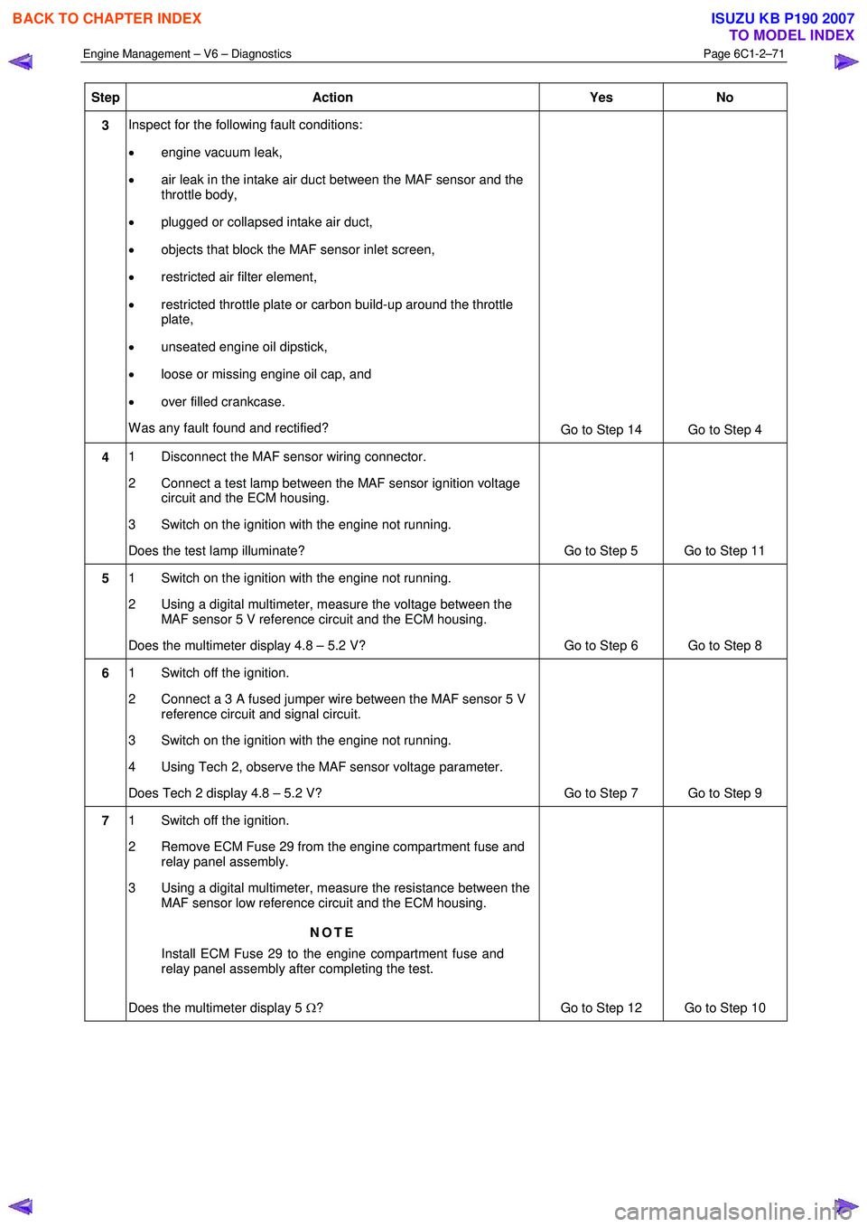
Step Action Yes No
3 Inspect for the following fault conditions:
• engine vacuum leak,
• air leak in the intake air duct between the MAF sensor and the
throttle body,
• plugged or collapsed intake air duct,
• objects that block the MAF sensor inlet screen,
• restricted air filter element,
• restricted throttle plate or carbon build-up around the throttle
plate,
• unseated engine oil dipstick,
• loose or missing engine oil cap, and
• over filled crankcase.
W as any fault found and rectified? Go to Step 14 Go to Step 4
4 1 Disconnect the MAF sensor wiring connector.
2 Connect a test lamp between the MAF sensor ignition voltage circuit and the ECM housing.
3 Switch on the ignition with the engine not running.
Does the test lamp illuminate? Go to Step 5 Go to Step 11
5 1 Switch on the ignition with the engine not running.
2 Using a digital multimeter, measure the voltage between the MAF sensor 5 V reference circuit and the ECM housing.
Does the multimeter display 4.8 – 5.2 V? Go to Step 6 Go to Step 8
6 1 Switch off the ignition.
2 Connect a 3 A fused jumper wire between the MAF sensor 5 V reference circuit and signal circuit.
3 Switch on the ignition with the engine not running.
4 Using Tech 2, observe the MAF sensor voltage parameter.
Does Tech 2 display 4.8 – 5.2 V? Go to Step 7 Go to Step 9
7 1 Switch off the ignition.
2 Remove ECM Fuse 29 from the engine compartment fuse and relay panel assembly.
3 Using a digital multimeter, measure the resistance between the MAF sensor low reference circuit and the ECM housing.
NOTE
Install ECM Fuse 29 to the engine compartment fuse and
relay panel assembly after completing the test.
Does the multimeter display 5 Ω? Go to Step 12 Go to Step 10
BACK TO CHAPTER INDEX
TO MODEL INDEX
ISUZU KB P190 2007
Page 3352 of 6020
Engine Management – V6 – Diagnostics Page 6C1-2–74
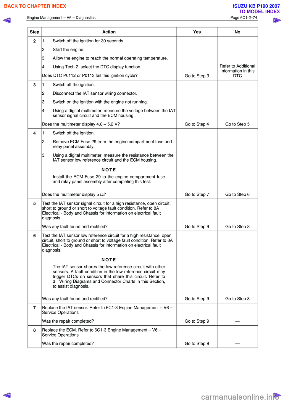
Step Action Yes No
2 1 Switch off the ignition for 30 seconds.
2 Start the engine.
3 Allow the engine to reach the normal operating temperature.
4 Using Tech 2, select the DTC display function.
Does DTC P0112 or P0113 fail this ignition cycle? Go to Step 3 Refer to Additional
Information in this DTC
3 1 Switch off the ignition.
2 Disconnect the IAT sensor wiring connector.
3 Switch on the ignition with the engine not running.
4 Using a digital multimeter, measure the voltage between the IAT sensor signal circuit and the ECM housing.
Does the multimeter display 4.8 – 5.2 V? Go to Step 4 Go to Step 5
4 1 Switch off the ignition.
2 Remove ECM Fuse 29 from the engine compartment fuse and relay panel assembly.
3 Using a digital multimeter, measure the resistance between the IAT sensor low reference circuit and the ECM housing.
NOTE
Install the ECM Fuse 29 to the engine compartment fuse
and relay panel assembly after completing this test.
Does the multimeter display 5 Ω? Go to Step 7 Go to Step 6
5 Test the IAT sensor signal circuit for a high resistance, open circuit,
short to ground or short to voltage fault condition. Refer to 8A
Electrical - Body and Chassis for information on electrical fault
diagnosis.
W as any fault found and rectified? Go to Step 9 Go to Step 8
6 Test the IAT sensor low reference circuit for a high resistance, open
circuit, short to ground or short to voltage fault condition. Refer to 8A
Electrical - Body and Chassis for information on electrical fault
diagnosis.
NOTE
The IAT sensor shares the low reference circuit with other
sensors. A fault condition in the low reference circuit may
trigger DTCs on sensors that share this circuit. Refer to
3 W iring Diagrams and Connector Charts in this Section,
to assist diagnosis.
W as any fault found and rectified? Go to Step 9 Go to Step 8
7 Replace the IAT sensor. Refer to 6C1-3 Engine Management – V6 –
Service Operations
W as the repair completed? Go to Step 9 —
8 Replace the ECM. Refer to 6C1-3 Engine Management – V6 –
Service Operations
W as the repair completed? Go to Step 9 —
BACK TO CHAPTER INDEX
TO MODEL INDEX
ISUZU KB P190 2007