2007 ISUZU KB P190 oil temperature
[x] Cancel search: oil temperaturePage 4266 of 6020
CONSTRUCTION AND FUNCTION 7A1-27
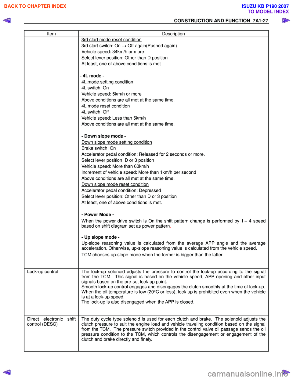
Item Description
3rd start mode reset condition
3rd start switch: On → Off again(Pushed again)
Vehicle speed: 34km/h or more
Select lever position: Other than D position
At least, one of above conditions is met.
- 4L mode -
4L mode setting condition
4L switch: On
Vehicle speed: 5km/h or more
Above conditions are all met at the same time.
4L mode reset condition
4L switch: Off
Vehicle speed: Less than 5km/h
Above conditions are all met at the same time.
- Down slope mode -
Down slope mode setting condition
Brake switch: On
Accelerator pedal condition: Released for 2 seconds or more.
Select lever position: D or 3 position
Vehicle speed: More than 60km/h
Increment of vehicle speed: More than 1km/h per second
Above conditions are all met at the same time.
Down slope mode reset condition
Accelerator pedal condition: Depressed
Select lever position: Other than D or 3 position
At least, one of above conditions is met.
- Power Mode -
W hen the power drive switch is On the shift pattern change is performed by 1 – 4 speed
based on shift diagram set as power pattern .
- Up slope mode -
Up-slope reasoning value is calculated from the average APP angle and the average
acceleration. Otherwise, up-slope reasoning value is calculated from the vehicle speed.
TCM chooses up-slope mode when the former is bigger than the latter.
Lock-up control The lock-up solenoid adjusts the pressure to control the lock-up according to the signal
from the TCM. This signal is based on the vehicle speed, APP opening and other input
signals based on the pre-set lock-up point.
Smooth lock-up control engages and disengages the clutch smoothly at the time of lock-up.
W hen the oil temperature is low (20°C or less), lock-up is prohibited even when the vehicle
is at a lock-up speed.
The lock-up is also disengaged when the APP is closed.
Direct electronic shift
control (DESC)
The duty cycle type solenoid is used for each clutch and brake. The solenoid adjusts the
clutch pressure to suit the engine load and vehicle traveling condition based on the signal
from the TCM. The pressure switch provided in the control valve oil passage sends the oil
pressure condition to the TCM, which controls the disengagement or engagement of the
clutch and brake directly and finely.
BACK TO CHAPTER INDEX
TO MODEL INDEX
ISUZU KB P190 2007
Page 4268 of 6020

CONSTRUCTION AND FUNCTION 7A1-29
CONTROL ITEM, INPUT AND OUTPUT
Control item
Item
Line
pressure control
Gear shift
control
Shift
pattern
selection
Lock-up control Direct
electronic shift
control
(DECS)
Learning control
Fail-safe function
Self-
diagnosis function
Speed sensor
Turbine sensor
Engine speed sensor
Brake switch
Inhibitor switch
Mode select switch
4L switch (4W D Only)
ATF thermo sensor
High clutch oil pressure switch
2-4 brake oil pressure switch
Low & Reverse brake oil pressure
switch
Input
Accelerator Pedal position sensor
Line pressure solenoid
Low clutch solenoid
High clutch solenoid
2-4 brake solenoid
Low & Reverse brake solenoid
Lock-up solenoid
Shift pattern indicator lamp
ATF temperature indicator lamp
Output
Check trans indicator lamp
BACK TO CHAPTER INDEX
TO MODEL INDEX
ISUZU KB P190 2007
Page 4269 of 6020
7A1-30 CONSTRUCTION AND FUNCTION
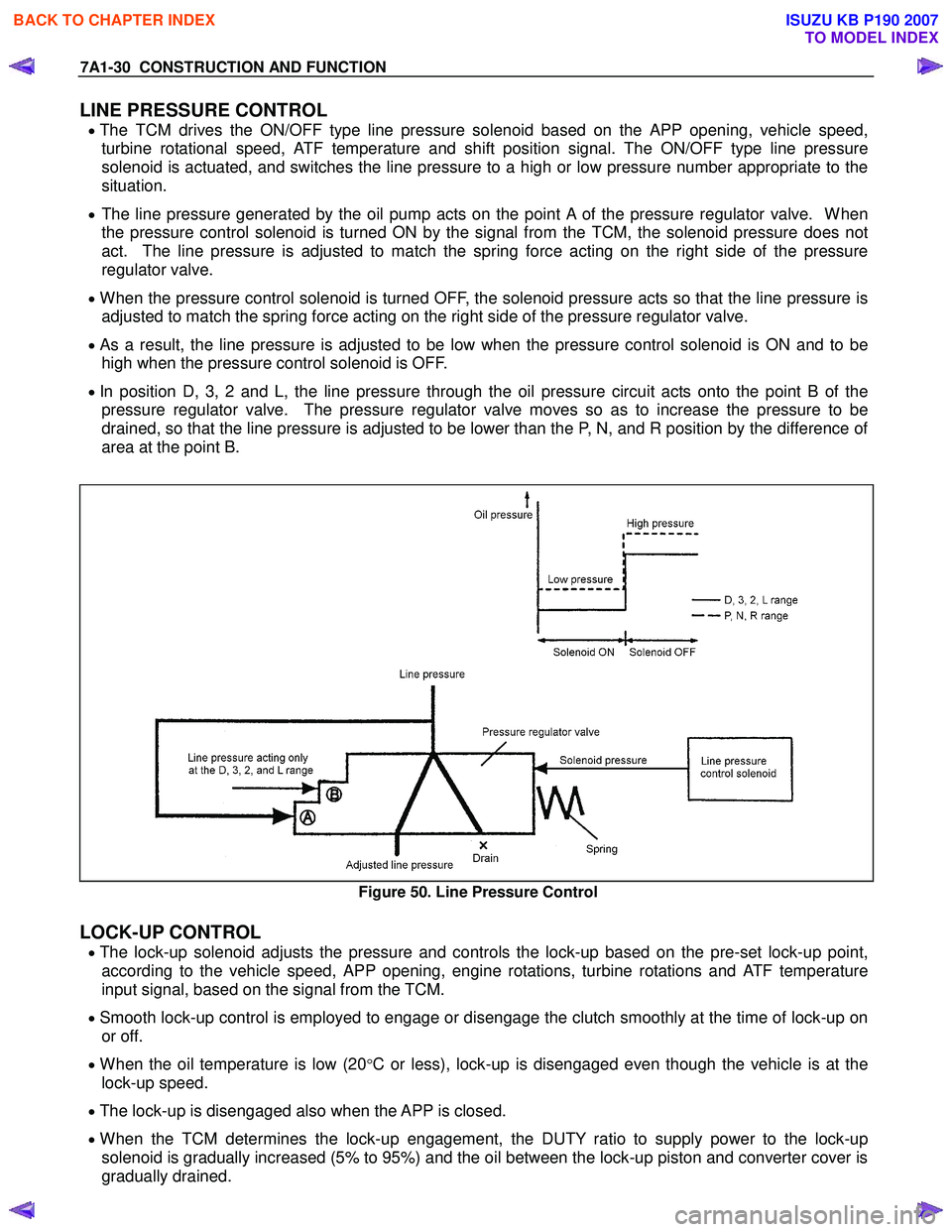
LINE PRESSURE CONTROL
• The TCM drives the ON/OFF type line pressure solenoid based on the APP opening, vehicle speed,
turbine rotational speed, ATF temperature and shift position signal. The ON/OFF type line pressure
solenoid is actuated, and switches the line pressure to a high or low pressure number appropriate to the
situation.
• The line pressure generated by the oil pump acts on the point A of the pressure regulator valve. When
the pressure control solenoid is turned ON by the signal from the TCM, the solenoid pressure does not
act. The line pressure is adjusted to match the spring force acting on the right side of the pressure
regulator valve.
• When the pressure control solenoid is turned OFF, the solenoid pressure acts so that the line pressure is
adjusted to match the spring force acting on the right side of the pressure regulator valve.
• As a result, the line pressure is adjusted to be low when the pressure control solenoid is ON and to be
high when the pressure control solenoid is OFF.
• In position D, 3, 2 and L, the line pressure through the oil pressure circuit acts onto the point B of the
pressure regulator valve. The pressure regulator valve moves so as to increase the pressure to be
drained, so that the line pressure is adjusted to be lower than the P, N, and R position by the difference of
area at the point B.
Figure 50. Line Pressure Control
LOCK-UP CONTROL
• The lock-up solenoid adjusts the pressure and controls the lock-up based on the pre-set lock-up point,
according to the vehicle speed, APP opening, engine rotations, turbine rotations and ATF temperature
input signal, based on the signal from the TCM.
• Smooth lock-up control is employed to engage or disengage the clutch smoothly at the time of lock-up on
or off.
• When the oil temperature is low (20°C or less), lock-up is disengaged even though the vehicle is at the
lock-up speed.
• The lock-up is disengaged also when the APP is closed.
• When the TCM determines the lock-up engagement, the DUTY ratio to supply power to the lock-up
solenoid is gradually increased (5% to 95%) and the oil between the lock-up piston and converter cover is
gradually drained.
BACK TO CHAPTER INDEX
TO MODEL INDEX
ISUZU KB P190 2007
Page 4273 of 6020
7A1-34 CONSTRUCTION AND FUNCTION
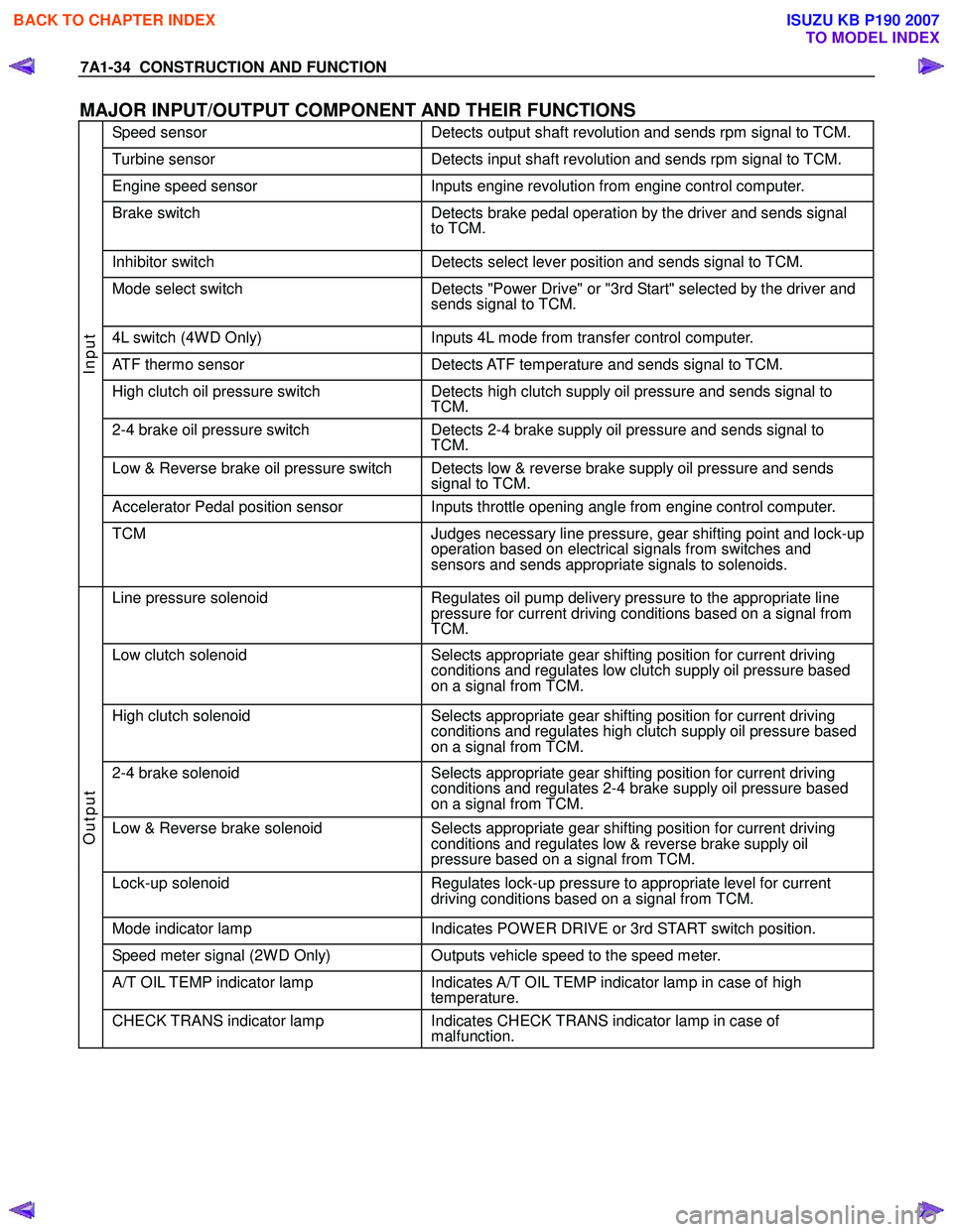
MAJOR INPUT/OUTPUT COMPONENT AND THEIR FUNCTIONS
Speed sensor Detects output shaft revolution and sends rpm signal to TCM.
Turbine sensor Detects input shaft revolution and sends rpm signal to TCM.
Engine speed sensor Inputs engine revolution from engine control computer.
Brake switch Detects brake pedal operation by the driver and sends signal
to TCM.
Inhibitor switch Detects select lever position and sends signal to TCM.
Mode select switch Detects "Power Drive" or "3rd Start" selected by the driver and
sends signal to TCM.
4L switch (4W D Only) Inputs 4L mode from transfer control computer.
ATF thermo sensor Detects ATF temperature and sends signal to TCM.
High clutch oil pressure switch Detects high clutch supply oil pressure and sends signal to
TCM.
2-4 brake oil pressure switch Detects 2-4 brake supply oil pressure and sends signal to
TCM.
Low & Reverse brake oil pressure switch Detects low & reverse brake supply oil pressure and sends signal to TCM.
Accelerator Pedal position sensor Inputs throttle opening angle from engine control computer.
Input
TCM Judges necessary line pressure, gear shifting point and lock-up
operation based on electrical signals from switches and
sensors and sends appropriate signals to solenoids.
Line pressure solenoid Regulates oil pump delivery pressure to the appropriate line
pressure for current driving conditions based on a signal from
TCM.
Low clutch solenoid Selects appropriate gear shifting position for current driving
conditions and regulates low clutch supply oil pressure based
on a signal from TCM.
High clutch solenoid Selects appropriate gear shifting position for current driving
conditions and regulates high clutch supply oil pressure based
on a signal from TCM.
2-4 brake solenoid Selects appropriate gear shifting position for current driving
conditions and regulates 2-4 brake supply oil pressure based
on a signal from TCM.
Low & Reverse brake solenoid Selects appropriate gear shifting position for current driving
conditions and regulates low & reverse brake supply oil
pressure based on a signal from TCM.
Lock-up solenoid Regulates lock-up pressure to appropriate level for current
driving conditions based on a signal from TCM.
Mode indicator lamp Indicates POW ER DRIVE or 3rd START switch position.
Speed meter signal (2W D Only) Outputs vehicle speed to the speed meter.
A/T OIL TEMP indicator lamp Indicates A/T OIL TEMP indicator lamp in case of high
temperature.
Output
CHECK TRANS indicator lamp Indicates CHECK TRANS indicator lamp in case of
malfunction.
BACK TO CHAPTER INDEX
TO MODEL INDEX
ISUZU KB P190 2007
Page 4274 of 6020
CONSTRUCTION AND FUNCTION 7A1-35
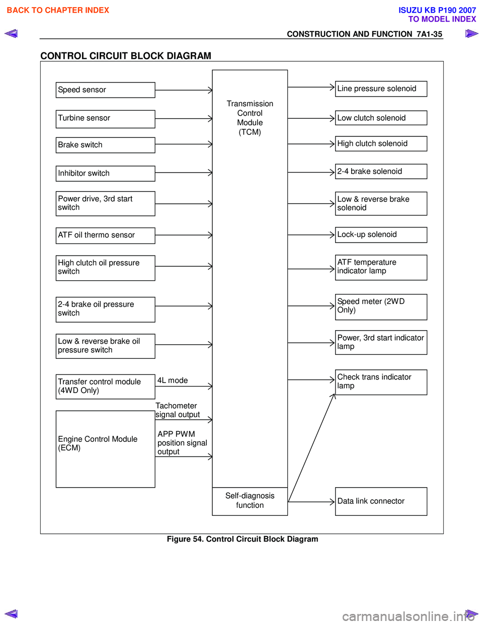
CONTROL CIRCUIT BLOCK DIAGRAM
Speed sensor
Turbine sensor
Brake switch
Inhibitor switch
Power drive, 3rd start
switch
ATF oil thermo sensor
High clutch oil pressure
switch
2-4 brake oil pressure
switch
Low & reverse brake oil
pressure switch
Transfer control module
(4W D Only)
Engine Control Module
(ECM)
Line pressure solenoid
Low clutch solenoid
High clutch solenoid
2-4 brake solenoid
Low & reverse brake
solenoid
Lock-up solenoid
ATF temperature
indicator lamp
Speed meter (2W D
Only)
Power, 3rd start indicator
lamp
Check trans indicator
lamp
Data link connector Self-diagnosis
function
Transmission
Control
Module (TCM)
4L mode
Tachometer
signal output
APP PW M
position signal
output
Figure 54. Control Circuit Block Diagram
BACK TO CHAPTER INDEX
TO MODEL INDEX
ISUZU KB P190 2007
Page 4301 of 6020
TRANSMISSION CONTROL SYSTEM (JR405E) 7A2-17
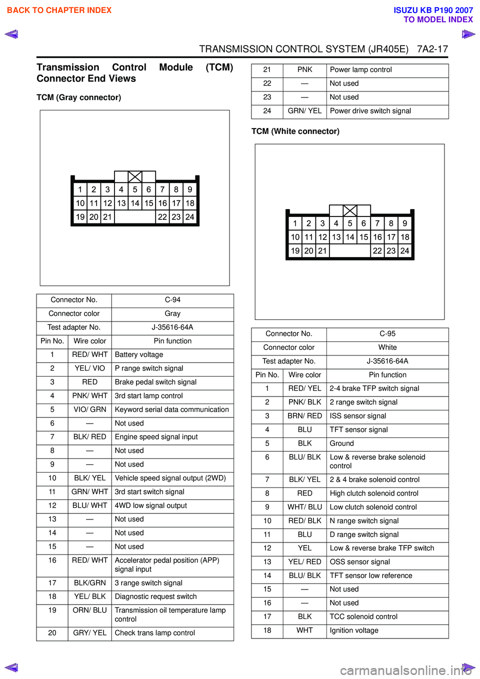
Transmission Control Module (TCM)
Connector End Views
TCM (Gray connector)
TCM (White connector)
Connector No.C-94
Connector color Gray
Test adapter No. J-35616-64A
Pin No. Wire color Pin function
1 RED/ WHT Battery voltage
2 YEL/ VIO P range switch signal
3 RED Brake pedal switch signal
4 PNK/ WHT 3rd start lamp control
5 VIO/ GRN Keyword serial data communication
6 — Not used
7 BLK/ RED Engine speed signal input
8 — Not used
9 — Not used
10 BLK/ YEL Vehicle speed signal output (2WD)
11 GRN/ WHT 3rd start switch signal
12 BLU/ WHT 4WD low signal output
13 — Not used
14 — Not used
15 — Not used
16 RED/ WHT Accelerator pedal position (APP) signal input
17 BLK/GRN 3 range switch signal
18 YEL/ BLK Diagnostic request switch
19 ORN/ BLU Transmission oil temperature lamp control
20 GRY/ YEL Check trans lamp control
1
10
19
2
11
20
3
12
21
4
13
5
14
6
15
7
16
22
8
17
23
9
18
24
21 PNK Power lamp control
22 — Not used
23 — Not used
24 GRN/ YEL Power drive switch signal
Connector No. C-95
Connector color White
Test adapter No. J-35616-64A
Pin No. Wire color Pin function
1 RED/ YEL 2-4 brake TFP switch signal
2 PNK/ BLK 2 range switch signal
3 BRN/ RED ISS sensor signal
4 BLU TFT sensor signal
5 BLK Ground
6 BLU/ BLK Low & reverse brake solenoid control
7 BLK/ YEL 2 & 4 brake solenoid control
8 RED High clutch solenoid control
9 WHT/ BLU Low clutch solenoid control
10 RED/ BLK N range switch signal 11 BLU D range switch signal
12 YEL Low & reverse brake TFP switch
13 YEL/ RED OSS sensor signal
14 BLU/ BLK TFT sensor low reference
15 — Not used
16 — Not used
17 BLK TCC solenoid control
18 WHT Ignition voltage
1
10
19
2
11
20
3
12
21
4
13
5
14
6
15
7
16
22
8
17
23
9
18
24
BACK TO CHAPTER INDEX
TO MODEL INDEX
ISUZU KB P190 2007
Page 4308 of 6020
7A2-24 TRANSMISSION CONTROL SYSTEM (JR405E)
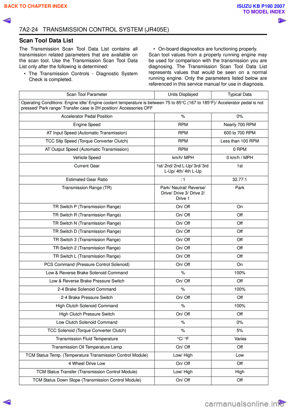
Scan Tool Data List
The Transmission Scan Tool Data List contains all
transmission related parameters that are available on
the scan tool. Use the Transmission Scan Tool Data
List only after the following is determined:
• The Transmission Controls - Diagnostic System Check is completed. • On-board diagnostics are functioning properly.
Scan tool values from a properly running engine may
be used for comparison with the transmission you are
diagnosing. The Transmission Scan Tool Data List
represents values that would be seen on a normal
running engine. Only the parameters listed below are
referenced in this service manual for use in diagnosis.
Scan Tool Parameter Units DisplayedTypical Data
Operating Conditions: Engine idle/ Engine coolant temperature is between 75 to 85 °C (167 to 185 °F)/ Accelerator pedal is not
pressed/ Park range/ Transfer case is 2H position/ Accessories OFF
Accelerator Pedal Position %0%
Engine Speed RPMNearly 700 RPM
AT Input Speed (Automatic Transmission) RPM600 to 700 RPM
TCC Slip Speed (Torque Converter Clutch) RPMLess than 100 RPM
AT Output Speed (Automatic Transmission) RPM0 RPM
Vehicle Speed km/h/ MPH0 km/h / MPH
Current Gear 1st/ 2nd/ 2nd L-Up/ 3rd/ 3rd
L-Up/ 4th/ 4th L-Up 1st
Estimated Gear Ratio : 132.77:1
Transmission Range (TR) Park/ Neutral/ Reverse/
Drive/ Drive 3/ Drive 2/ Drive 1 Park
TR Switch P (Transmission Range) On/ OffOn
TR Switch R (Transmission Range) On/ OffOff
TR Switch N (Transmission Range) On/ OffOff
TR Switch D (Transmission Range) On/ OffOff
TR Switch 3 (Transmission Range) On/ OffOff
TR Switch 2 (Transmission Range) On/ OffOff
TR Switch L (Transmission Range) On/ OffOff
PCS Command (Pressure Control Solenoid) On/ OffOn
Low & Reverse Brake Solenoid Command %100%
Low & Reverse Brake Pressure Switch On/ OffOff
2-4 Brake Solenoid Command %100%
2-4 Brake Pressure Switch On/ OffOff
High Clutch Solenoid Command %100%
High Clutch Pressure Switch On/ OffOff
Low Clutch Solenoid Command %0%
TCC Solenoid (Torque Converter Clutch) %5%
Transmission Fluid Temperature °C/ °F V arie s
Transmission Oil Temperature Lamp On/ OffOff
TCM Status Temp. (Temperature Transmission Control Module) Low/ HighLow
4 Wheel Drive Low On/ OffOff
TCM Status Transfer (Transmission Control Module) Low/ HighHigh
TCM Status Down Slope (Transmission Control Module) On/ OffOff
BACK TO CHAPTER INDEX
TO MODEL INDEX
ISUZU KB P190 2007
Page 4310 of 6020
7A2-26 TRANSMISSION CONTROL SYSTEM (JR405E)
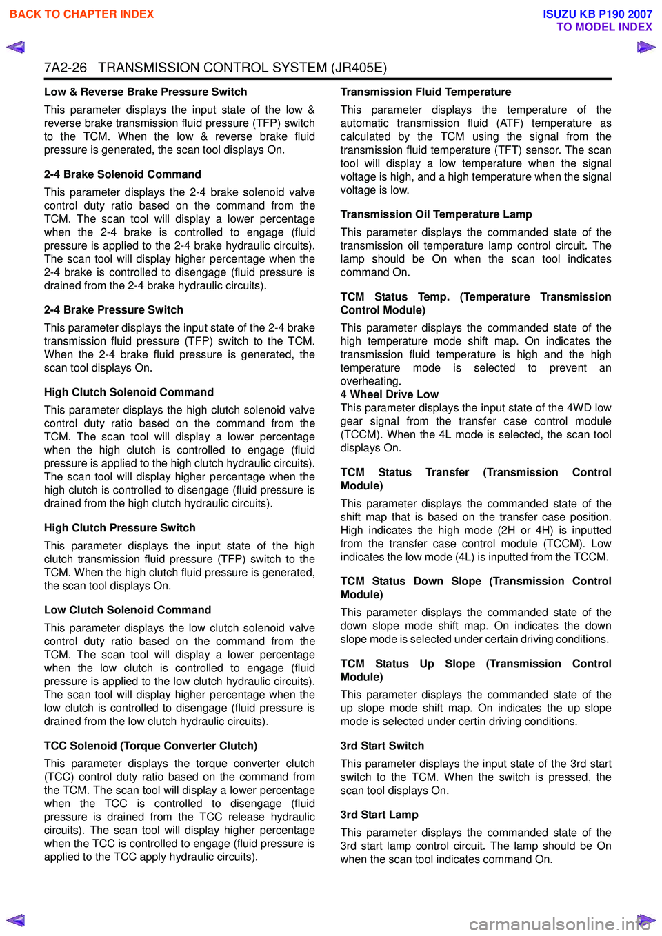
Low & Reverse Brake Pressure Switch
This parameter displays the input state of the low &
reverse brake transmission fluid pressure (TFP) switch
to the TCM. When the low & reverse brake fluid
pressure is generated, the scan tool displays On.
2-4 Brake Solenoid Command
This parameter displays the 2-4 brake solenoid valve
control duty ratio based on the command from the
TCM. The scan tool will display a lower percentage
when the 2-4 brake is controlled to engage (fluid
pressure is applied to the 2-4 brake hydraulic circuits).
The scan tool will display higher percentage when the
2-4 brake is controlled to disengage (fluid pressure is
drained from the 2-4 brake hydraulic circuits).
2-4 Brake Pressure Switch
This parameter displays the input state of the 2-4 brake
transmission fluid pressure (TFP) switch to the TCM.
When the 2-4 brake fluid pressure is generated, the
scan tool displays On.
High Clutch Solenoid Command
This parameter displays the high clutch solenoid valve
control duty ratio based on the command from the
TCM. The scan tool will display a lower percentage
when the high clutch is controlled to engage (fluid
pressure is applied to the high clutch hydraulic circuits).
The scan tool will display higher percentage when the
high clutch is controlled to disengage (fluid pressure is
drained from the high clutch hydraulic circuits).
High Clutch Pressure Switch
This parameter displays the input state of the high
clutch transmission fluid pressure (TFP) switch to the
TCM. When the high clutch fluid pressure is generated,
the scan tool displays On.
Low Clutch Solenoid Command
This parameter displays the low clutch solenoid valve
control duty ratio based on the command from the
TCM. The scan tool will display a lower percentage
when the low clutch is controlled to engage (fluid
pressure is applied to the low clutch hydraulic circuits).
The scan tool will display higher percentage when the
low clutch is controlled to disengage (fluid pressure is
drained from the low clutch hydraulic circuits).
TCC Solenoid (Torque Converter Clutch)
This parameter displays the torque converter clutch
(TCC) control duty ratio based on the command from
the TCM. The scan tool will display a lower percentage
when the TCC is controlled to disengage (fluid
pressure is drained from the TCC release hydraulic
circuits). The scan tool will display higher percentage
when the TCC is controlled to engage (fluid pressure is
applied to the TCC apply hydraulic circuits). Transmission Fluid Temperature
This parameter displays the temperature of the
automatic transmission fluid (ATF) temperature as
calculated by the TCM using the signal from the
transmission fluid temperature (TFT) sensor. The scan
tool will display a low temperature when the signal
voltage is high, and a high temperature when the signal
voltage is low.
Transmission Oil Temperature Lamp
This parameter displays the commanded state of the
transmission oil temperature lamp control circuit. The
lamp should be On when the scan tool indicates
command On.
TCM Status Temp. (Temperature Transmission
Control Module)
This parameter displays the commanded state of the
high temperature mode shift map. On indicates the
transmission fluid temperature is high and the high
temperature mode is selected to prevent an
overheating.
4 Wheel Drive Low
This parameter displays the input state of the 4WD low
gear signal from the transfer case control module
(TCCM). When the 4L mode is selected, the scan tool
displays On.
TCM Status Transfer (Transmission Control
Module)
This parameter displays the commanded state of the
shift map that is based on the transfer case position.
High indicates the high mode (2H or 4H) is inputted
from the transfer case control module (TCCM). Low
indicates the low mode (4L) is inputted from the TCCM.
TCM Status Down Slope (Transmission Control
Module)
This parameter displays the commanded state of the
down slope mode shift map. On indicates the down
slope mode is selected under certain driving conditions.
TCM Status Up Slope (Transmission Control
Module)
This parameter displays the commanded state of the
up slope mode shift map. On indicates the up slope
mode is selected under certin driving conditions.
3rd Start Switch
This parameter displays the input state of the 3rd start
switch to the TCM. When the switch is pressed, the
scan tool displays On.
3rd Start Lamp
This parameter displays the commanded state of the
3rd start lamp control circuit. The lamp should be On
when the scan tool indicates command On.
BACK TO CHAPTER INDEX
TO MODEL INDEX
ISUZU KB P190 2007